 ElectroScope Archive
Project Overview
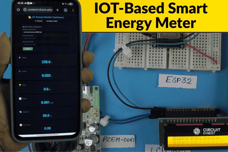
This project turns a basic energy meter into a connected, real-time monitoring system that delivers electrical metrics to the cloud and notifies you by SMS when something goes wrong. An ESP32 microcontroller reads voltage, current, power, energy, frequency, and power factor from a PZEM-004T sensor. The device publishes these readings over MQTT to a dashboard and triggers SMS alerts via a cloud API for abnormal conditions like high voltage or overload.
Why This Matters
Standard utility meters don’t let you see or react to your power usage in real time. This build provides:
-
Live remote monitoring with a browser dashboard
-
Automatic SMS alerts on electrical anomalies
-
Local display of readings on an LCD
-
Low cost and open-source code with easy hardware integration
How It Works
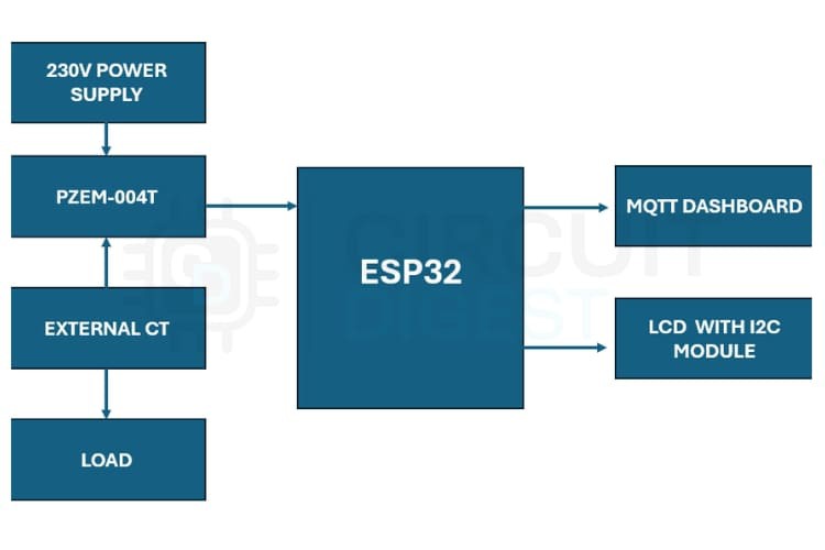
Sensors & Data Flow
-
PZEM-004T measures AC parameters using a current transformer and internal metering chip.
-
The ESP32 polls these values over UART (Modbus) and updates the LCD.
-
Readings are sent over Wi-Fi to an MQTT broker where a web dashboard displays them in real time.
-
If a condition exceeds a threshold (e.g., voltage spike), the ESP32 calls a cloud API to send an SMS alert.
![]()
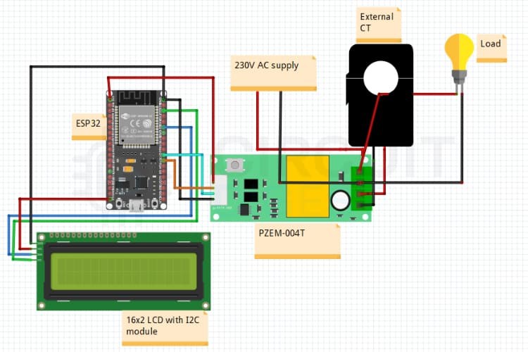
Circuit Summary
-
ESP32 RX/TX ↔ PZEM-004T UART
-
I2C (SDA/SCL) ↔ LCD for local readouts
-
Power from 5 V supply
-
CT around live conductor for current sensing
No mains is wired into the microcontroller — the PZEM module isolates the high voltage side.
Software Highlights
-
Wi-Fi & MQTT setup for remote publishing
-
Sensor polling loop reads voltage, current, power, etc.
-
SMS logic triggers when thresholds are exceeded
-
Dashboard code (HTML + JS) connects via WebSockets to MQTT topics for live UI updates
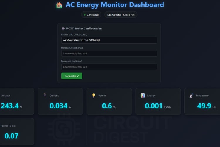
Dashboard
The dashboard (HTML + CSS) displays real-time values for all major electrical parameters. It connects to a public MQTT broker and auto-updates UI elements as new data arrives.
Practical Use Cases
-
Home power monitoring with alerts
-
Safety fault detection (overload, unexpected drops)
-
Remote management of vacation homes or installations
-
Integration with home automation systems via MQTT.
Building Tips
-
Place the CT clamp only around the live wire to avoid incorrect measurements.
-
Ensure the LCD’s I2C address matches what your code expects (0x27 or 0x3F).
-
Test SMS triggers with safe thresholds first.
What You’ll Need (Quick List)
-
ESP32 dev board
-
PZEM-004T + CT sensor
-
16×2 I2C LCD
-
Wi-Fi access
-
Circuit Digest Cloud account for free SMS API.

 mircemk
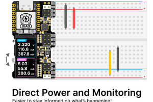
 nichod
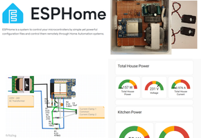
 Guido - IW5ALZ
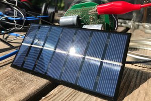
 Brian Sutherland