 Sagar 001
I love listening to music while working. Last week, I found my old earphones in a drawer. These are old-generation wired ones; the next second, the idea of turning them into wireless ones came into my mind. And here is our project: turning any wired headphones into wireless ones. Headphones and earphones both work with this custom device. Simply plug your device into the 3.5mm jack, slide the on/off switch, connect the Bluetooth to your device, and start listening. The overall story here is that I need a Bluetooth transceiver IC that can connect wirelessly to a device and some supporting circuitry. I have covered some projects in recent articles, see if you can relate.
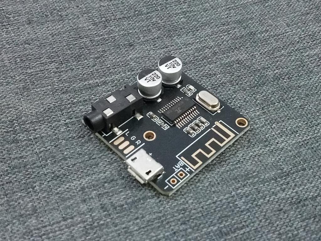
Well, this is not a new idea; the DF Robot already has one in production. First, I ordered one, and it works perfectly as I wanted. However, after using it for a day or so, I put my engineering mind to work and noted some modifications that can be made. That’s how I have added features like USB data support, USB Type-C power input, a Battery charging circuit, a switch, and a small battery. It is relatively easy if I simply add these things externally using modules, but I prefer a minimal system; that’s why it is better to build a PCB.
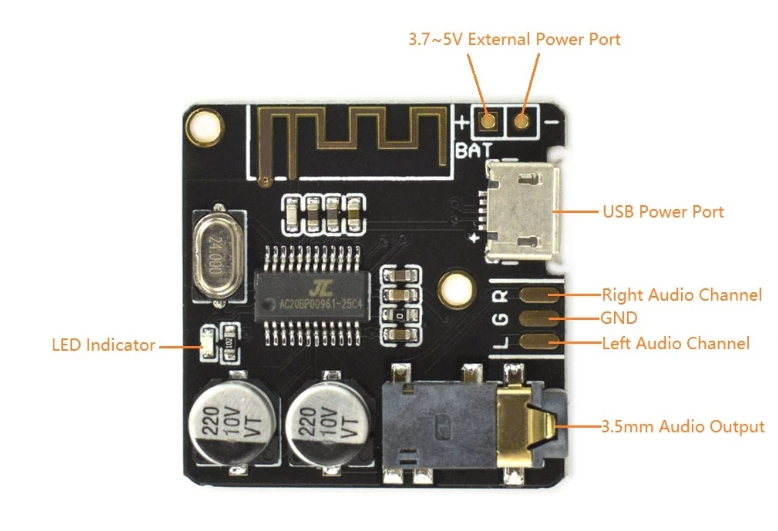
About the Bluetooth IC :
I recently posted an article about making wireless earphones using Bluetooth technology from Jieli, China. They made Bluetooth cards and audio processors. This company accounts for nearly 80% of the wireless Bluetooth market, and the product's datasheets are not available on the internet. That's why the products are cheaper; a 32-bit DSP with an ARM core is available for just $2.
However, the problem is that I do not know the IC internals, as there is no online data available from the official vendor. It is challenging to find PINs/functions. However, the modifications I want are relatively simple, so I reverse-engineered the circuit of the original board from the DF robot. All the information about the IC is shared here in the documentation I found on a random website after surfing through the web for almost 1.5 hours.
Components required:
I want to pair this IC with the TP4056 lithium battery charger module, so I desoldered all the components from the TP4056 board for this 5.0 Bluetooth. Find the full BOM file in the shared files below.
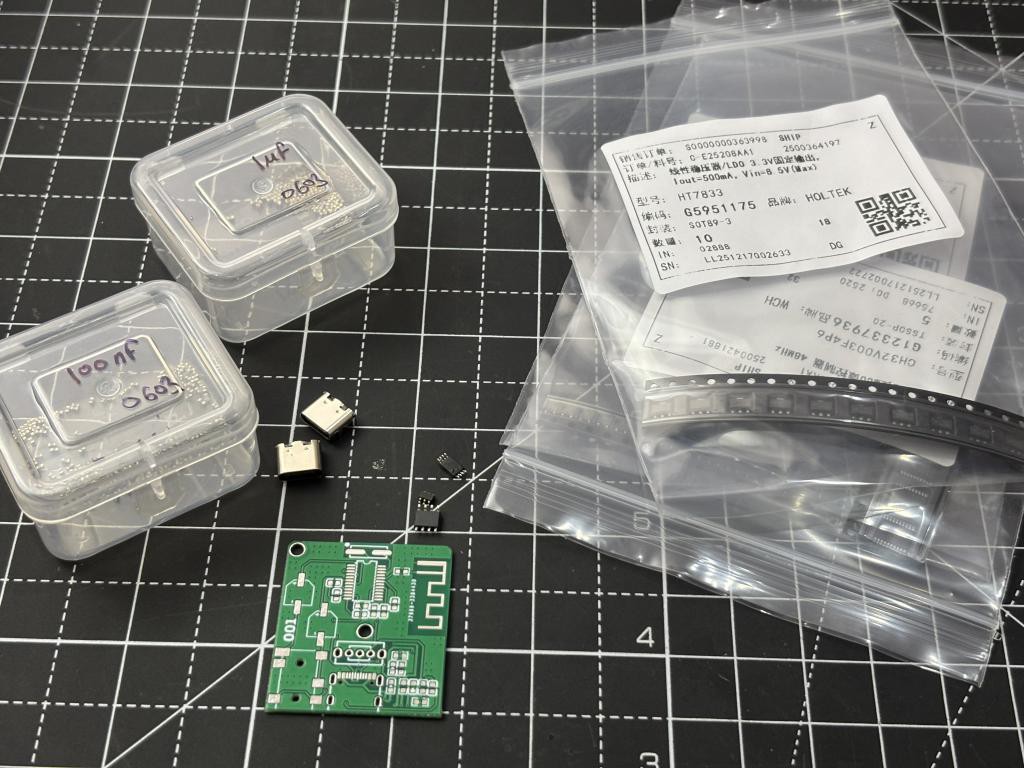
- TP4056 IC
- 8205A protection circuit (removed in update)
- JL 5.0 BT
- USB Type-C
- 3.5mm AUX Female jack
- 220u, 100n, 10u, 1n capacitors (all taken from old Bluetooth board)
- 24Mhz Crystal Oscillator
- 0603 LED Indicators
- 1K, 10K, 100R Resistors
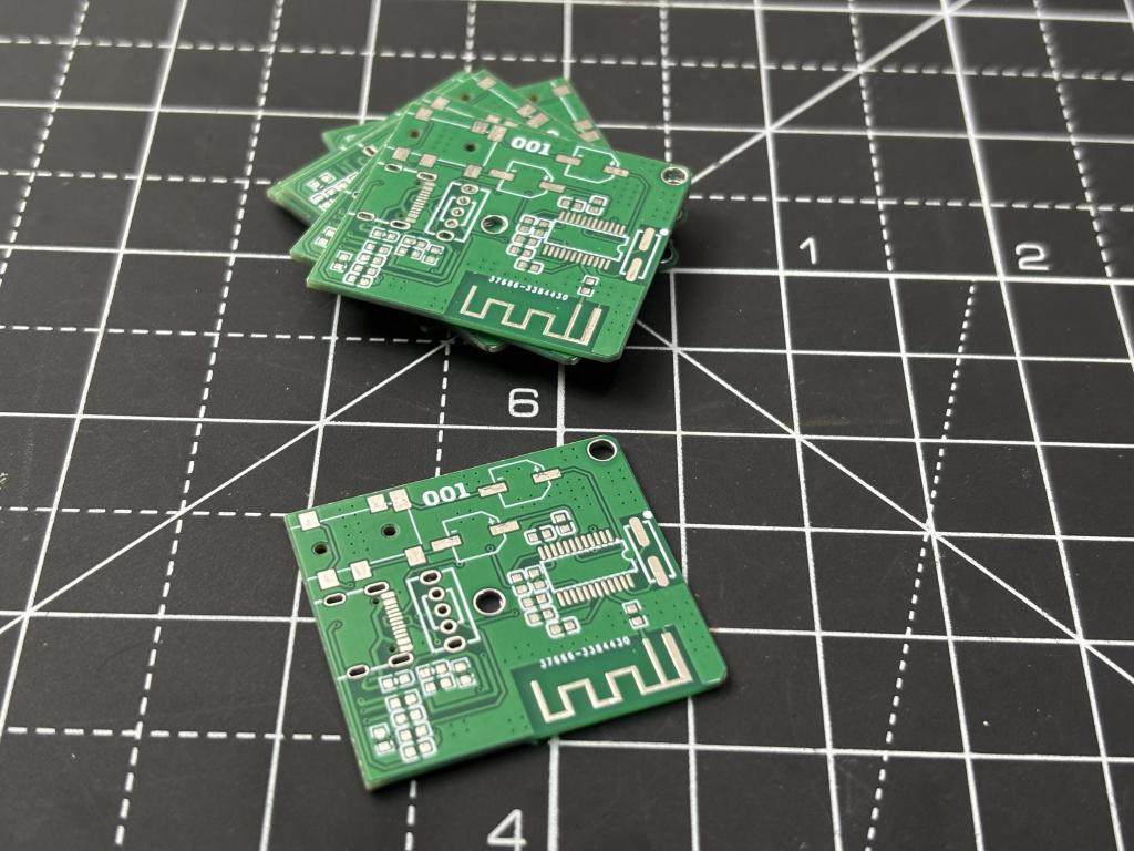
- PCB from NEXTPCB
Circuit Diagram:
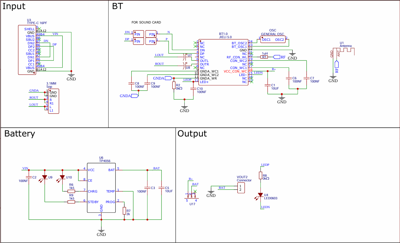
I redraw the circuit on paper and then finally on the EDA software. The modified circuit is given below, which contains the battery charging circuit, a switch for on/off, and a USB Type-C port with data handling capabilities. The primary challenge here is to arrange it on the PCB with a compact form factor. Because the circuit has components like an IFA antenna and an audio IC, I need decaps and grounding to maintain proper signal returns and power integrity. I have to keep the antenna and audio section away and isolate it from noise sources because it will affect the audio performance. I will explain how I redesigned this circuit to include Bluetooth audio.
PCB designs:
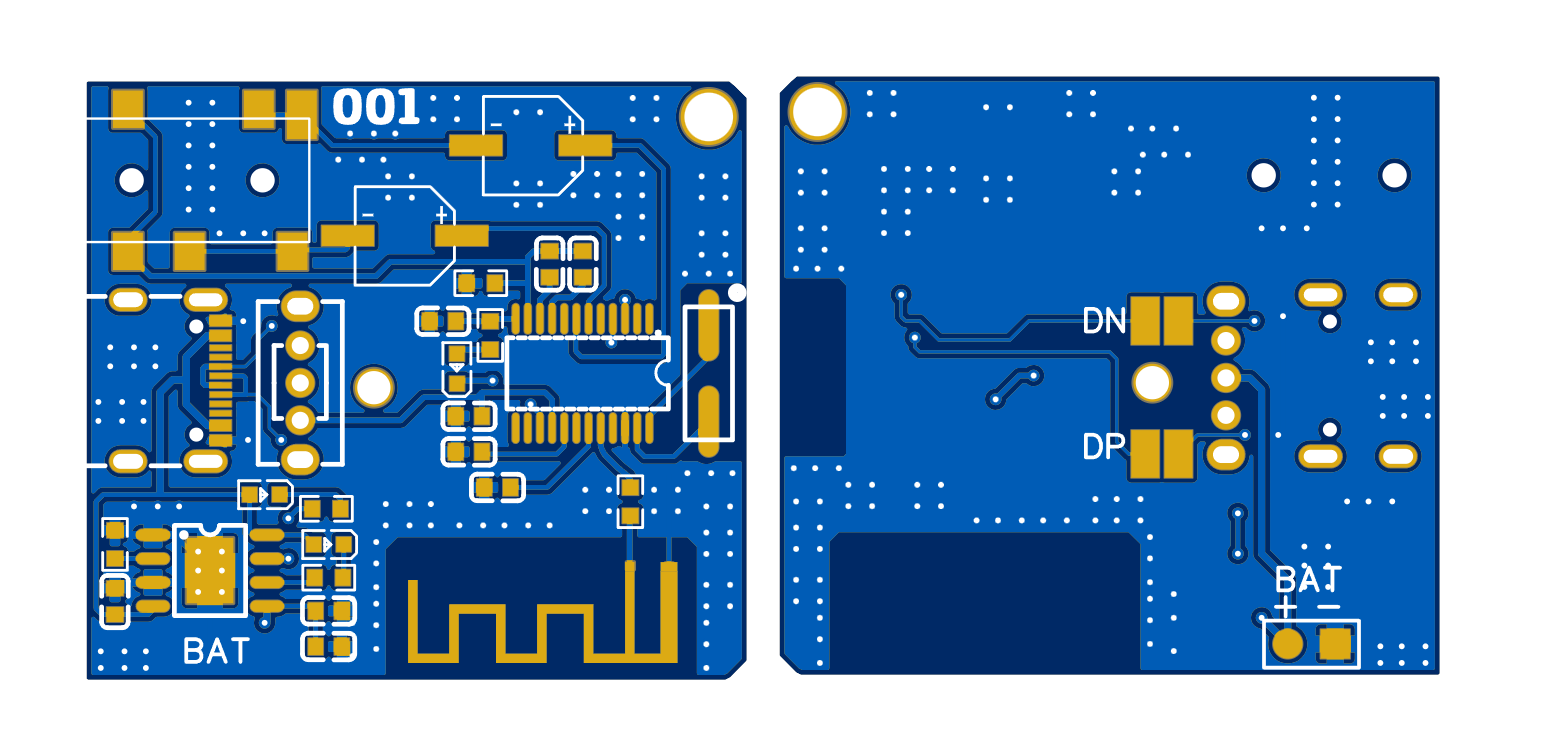
I used the standard battery charging circuit TP4056 with the protection IC, which is removed in the updated version due to the overall wide BOM. Because the Bluetooth IC itself has the features of undervoltage lockout. To minimise noise as much as possible, I have placed the analog components in the centre, away from the antenna and the battery charger. I followed the exact same placement rule as implemented in the original design. The PCB is slightly larger in size due to the addition of the battery charger, which is positioned away from the antenna. Via stitching is essential, as the board uses only two layers. To keep the inductance path as low as possible, the PCBs are fabricated with a thickness of 1.0mm.
The...
Read more »
 ElectroBoy
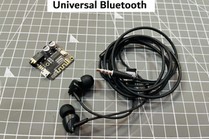
 Open Green Energy
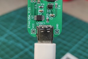
 DIY GUY Chris