 electronicsworkshops
Introduction
The Smart Electrical Parameter Monitoring, Fault Alert, and Control System is an embedded solution designed to monitor critical electrical parameters of a single-phase AC system, detect faults in real time, and take automatic protective actions. Traditional electrical systems rely heavily on manual inspection and basic protection devices, which may not provide early warnings or detailed system status. This project overcomes those limitations by combining isolated sensing circuits, intelligent processing using an ESP32 microcontroller, and automated control mechanisms, ensuring higher safety, reliability, and efficiency.
For Full Project:
https://electronicsworkshops.com/smart-electrical-parameter-monitoring-and-fault-alert-system/

Objectives
To continuously monitor AC voltage, phase presence, and load current
To detect electrical faults such as overvoltage, undervoltage, phase failure, and overcurrent
To provide real-time fault alerts and system status
To automatically control relays and cooling fans for protection and thermal management
To ensure electrical isolation and safety between high-voltage AC and low-voltage electronics
System Overview
The system works by first taking a single-phase AC input, from which voltage, phase, and load current are safely sensed using isolated potential and current transformers, then conditioned through filtering and amplifier circuits to produce low-voltage analog signals. These signals are fed into an ESP32 microcontroller, which continuously processes the data, compares it with predefined safe limits, and determines the system’s operating condition. If a fault such as overvoltage, undervoltage, phase loss, or overcurrent is detected, the controller immediately triggers alerts and control actions, including switching a relay to disconnect the load and activating cooling fans when required. A regulated 12 V to 5 V and 3.3 V power supply ensures stable operation of all electronics, while communication interfaces allow system expansion, making the overall flow a closed-loop process of sensing → decision-making → protection → control for safe and intelligent electrical system operation.
Fault Detection and Alert Logic
The system detects multiple fault conditions, including:
Overvoltage / Undervoltage – protects connected equipment from unstable supply
Phase Loss – prevents single-phasing damage
Overcurrent / Overload – avoids overheating and component failure
When a fault is detected:
A fault flag is generated internally
Control signals are immediately sent to disconnect or limit the load
Alerts can be transmitted to displays, indicators, or external systems
Circuit Diagram
This circuit is a single-phase AC monitoring and control module that measures AC voltage, phase presence, and load current, then uses that information to drive a relay and cooling fans safely with electrical isolation. The AC input (L, N) is stepped down and isolated using a potential transformer, and the reduced AC signal is conditioned by LM321 op-amp comparator circuits to generate logic-level signals labeled Voltage1 and Phase1, which indicate mains voltage availability and phase detection for a microcontroller. Current measurement is done through a current transformer (CT) at connector J1; its signal is rectified, filtered, and amplified by another LM321, producing a proportional Current output. On the control side, logic signals (RELAY_CONTROL, fan_control_1, fan_control_2) drive NPN transistors (2SD400A) that switch a relay and 12 V DC fans, with flyback diodes (1N4007) protecting against inductive spikes and polyfuses providing overcurrent protection. Overall, the circuit safely interfaces high-voltage AC with low-voltage electronics, enabling real-time monitoring and protective control of electrical loads—well suited for energy monitoring, protection systems, or EV/industrial applications.

A 12 V DC input from a barrel jack is stepped down to 5 V using...
Read more »
 keith.hungerford
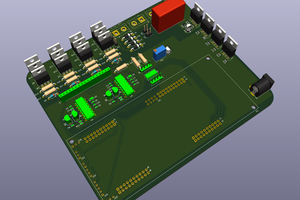
 novirium
 ElectroBoy