 Kutluhan Aktar
As I was reading about the applications of UV (ultraviolet) radiation in industrial operations, especially for anomaly detection, I became fascinated by the possibility of developing a proof-of-concept AI-driven industrial automation mechanism as a research project for detecting plastic surface anomalies. Due to the shorter wavelength of ultraviolet radiation, it can be employed in industrial machine vision systems to detect extremely small cracks, fissures, or gaps, as UV-exposure can reveal imperfections on which visible light bounces off, leading to catching some production line mistakes overlooked by the human eye or visible light-oriented camera sensors.
In the spirit of developing a proof-of-concept research project, I wanted to build an easily accessible, repeatable, and feature-rich AI-based mechanism to showcase as many different experiment parameters as I could. Nonetheless, I quickly realized that high-grade or even semi-professional UV-sensitive camera sensors were too expensive, complicated to implement, or somewhat restrictive for the features I envisioned. Even UV-only high-precision bandpass filters were too complex to utilize since they are specifically designed for a handful of high-end full-spectrum digital camera architectures. Therefore, I started to scrutinize the documentation of various commercially available camera sensors to find a suitable candidate to produce results for my plastic surface anomaly detection mechanism by the direct application of UV (ultraviolet radiation) to plastic object surfaces. After my research, I noticed that the Raspberry Pi camera module 3 was promising as a cost-effective option since it is based on the CMOS 12-megapixel Sony IMX708 image sensor, which provides more than 40% blue responsiveness for 400 nm. Although I knew the camera module 3 could not produce 100% accurate UV-induced photography without heavily modifying the Bayer layer and the integrated camera filters, I decided to purchase one and experiment to see whether I could generate accurate enough image samples by utilizing external camera filters, which exposes a sufficient discrepancy between plastic surfaces with different defect stages under UV lighting.
In this regard, I started to inspect various blocking camera filters to pinpoint the wavelength range I required — 100 - 400 nm — by absorbing visible light spectrums. After my research, I decided to utilize two different filter types separately to increase the breadth of UV-applied plastic surface image samples — a glass UV bandpass filter (ZWB ZB2) and color gel filters (with different light transmission levels - low, medium, high).
Since I did not want to constrain my experiments to only one quality control condition by UV-exposure, I decided to employ three different UV light sources providing different wavelengths of ultraviolet radiation — 275 nm, 365 nm, and 395 nm.
✅ DFRobot UVC Ultraviolet Germicidal Lamp Strip (275 nm)
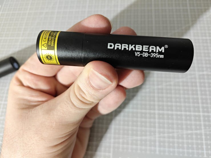
✅ DARKBEAM UV Flashlight (395 nm)
✅ DARKBEAM UV Flashlight (365 nm)
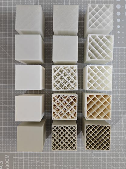
After conceptualizing my initial prototype with the mentioned components, I needed to find an applicable and repeatable method to produce plastic objects with varying stages of surface defects (none, high, and extreme), composed of different plastic materials. After thinking about different production methods, I decided to design a simple cube on Fusion 360 and alter the slicer settings to engender artificial but controlled surface defects (top layer bonding issues). In this regard, I was able to produce plastic objects (3D-printed) with a great deal of variation thanks to commercially available filament types, including UV-sensitive and reflective ones, resulting in an extensive image dataset of UV-applied plastic surfaces.
✅ Matte White
✅ Matte Khaki
✅ Shiny (Silk) White
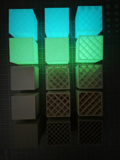
✅ UV-reactive White (Fluorescent Blue)
✅ UV-reactive White (Fluorescent Green)
Before proceeding with developing my industrial-grade proof-of-concept device, I needed to ensure that all...
Read more »


 Myrijam
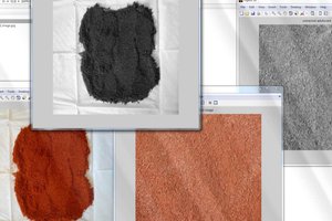
 G.Vignesh
 AIRPOCKET
Please feel free to leave a comment here if you have any questions or suggestions regarding this project 🙂