 Kutluhan Aktar
-
1Development process, different prototype versions, design failures, and final results
As I was developing this research project, I encountered lots of problems due to complex mechanical component designs, especially related to the sprocket-chain mechanism, leading me to go through five different iterations. I documented the overall development process for the final mechanism in the following written tutorial thoroughly and showcased the features of the final version in the project demonstration videos.
Every feature of the final version of this proof-of-concept automation mechanism worked as planned and anticipated after my adjustments, except that the stepper motors (Nema 17) around which I designed the primary internal gears could not handle the extra torque applied to my custom-designed ball bearings (with 5 mm steel beads) after I recalibrated the chain tension with additional tension pins. I explained the reasons for the tension recalibration thoroughly in the following steps. In this regard, I needed to record some features related to sprocket movements (affixed to outer gears pivoted on the ball bearings) by removing or loosening the chain for the demonstration videos.
-
2Step 2
As I briefly talked about my thought process for deciding the experiment parameters and sourcing components in the introduction, I will thoroughly cover the progress of building the UV-applied plastic surface image sample (data) collection rig in this section.
The simple data collection rig is the first version of this research project, which helped me to ensure that all components, camera filters, UV light sources, and plastic materials (filaments) I chose were compatible and sufficient to produce an extensive UV-applied plastic surface image dataset with enough discrepancy (contrast) to train a visual anomaly detection model.
As mentioned, after meticulously inspecting the documentation of various commercially available camera sensors, I decided to employ the Raspberry Pi camera module 3 Wide (120°) to capture images of plastic surfaces, showcasing different surface defect stages, under varying UV wavelengths. I studied the spectral sensitivity of the CMOS 12-megapixel Sony IMX708 image sensor and other available Raspberry Pi camera modules on the official Raspberry Pi camera documentation.
Since I decided to benefit from external camera filters to capture UV-oriented image samples with enough discrepancy (contrast) in accordance with the inherent surface defects, instead of heavily modifying the Bayer layer and the integrated camera filters, I sourced nearly full-spectrum color gel filters with different light transmission levels for blocking visible light. By stacking up these color gel filters, I managed to capture accurate UV-induced plastic surface images in the dark.
- Godox color gel filters with low light transmission
- Godox color gel filters with medium light transmission
- Godox color gel filters with high light transmission
![]()
![]()
Of course, only utilizing visible light-blocking color gel filters was not enough, considering the extent of this research study. In this regard, I also sourced a precise glass UV bandpass filter absorbing the visible light spectrum. Although I inspected the glass bandpass filter specifications from a different brand's documentation, I was only able to purchase one from AliExpress.
- UV bandpass filter (25 mm glass ZWB ZB2)
![]()
![]()
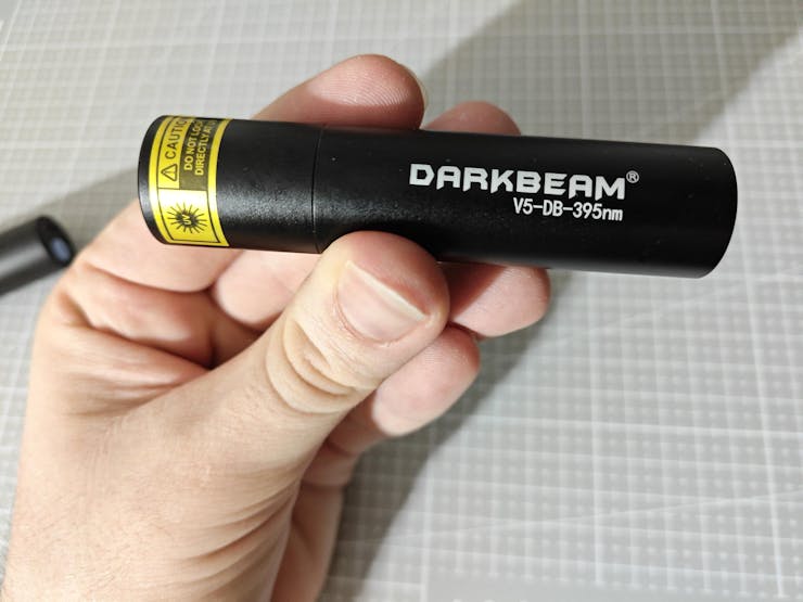
As I did not want to constrain this research project to showcase only one UV light source type while experimenting with quality control conditions by the direct application of UV (ultraviolet radiation) to plastic object surfaces, I decided to purchase three different UV light sources providing different UV wavelength ranges.
- DFRobot UVC Ultraviolet Germicidal Lamp Strip (275 nm)
- DARKBEAM UV Flashlight (395 nm)
- DARKBEAM UV Flashlight (365 nm)
![]()
![]()
![]()
Since I decided to manufacture plastic objects myself to control experiment parameters to develop a valid research project, I needed to find an applicable and repeatable method to produce plastic objects with varying stages of surface defects (none, high, and extreme) and source different plastic materials to produce a wide selection of plastic objects. After mulling over different production methods, I decided to produce my plastic objects with 3D printing and modify slicer settings to inflict artificial but controllable surface defects. Thanks to commercially available filament types, including UV-sensitive and reflective ones, I was able to source a great variety of materials to construct an extensive image dataset of UV-applied plastic surfaces.
- ePLA-Matte Milky White
- ePLA-Matte Light Khaki
- eSilk-PLA White (Shiny)
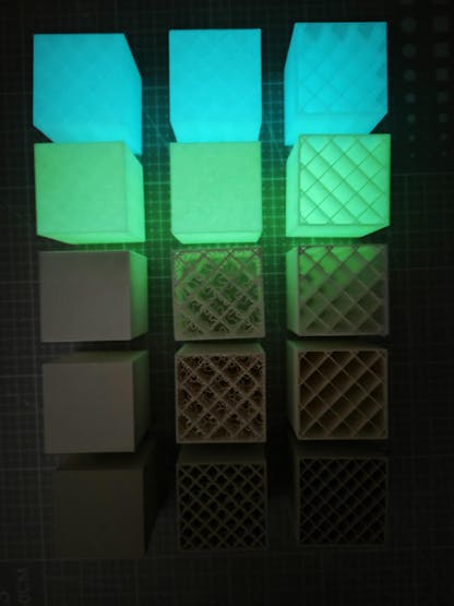
- PLA+ Luminous Green (UV-reactive - Fluorescent)
- PLA+ Luminous Blue (UV-reactive - Fluorescent)
#️⃣ First, I designed a simple cube on Autodesk Fusion 360 with dimensions of 40.00 mm x 40.00 mm x 40.00 mm.
![]()
#️⃣ I exported the cube as an STL file and uploaded the exported STL file to Bambu Studio.
#️⃣ Then, I modified the slicer (Bambu Studio) settings to implement artificial surface defects, in other words, inflicted top-layer bonding issues.
#️⃣ Since I wanted to showcase three different surface defect stages — none, high, and extreme — I copied the cube three times on the slicer.
#️⃣ For all three cubes, I selected the sparse infill density as 10% to outline the inflicted surface defects.
#️⃣ I utilized the standard slicer settings for the first cube, depicting the none surface defect stage.
![]()
#️⃣ For the second cube, I reduced the top shell layer number to 0 and selected the top surface pattern as the monotonic line, representing the extreme surface defect stage.
![]()
#️⃣ For the third cube, I lowered the top shell layer number to 1 and selected the top surface pattern as the Hilbert curve, representing the high surface defect stage.
![]()
![]()
#️⃣ However, as shown in the print preview, only reducing the top shell layer number would not lead to a protruding high defect stage, as I had hoped. Thus, I also reduced the top shell thickness to 0 to get the results I anticipated.
![]()
![]()
![]()
![]()
#️⃣ Since I decided to add the matte light khaki filament latest, I sliced three khaki cubes with 15% sparse infill density to expand my plastic object sample size.
![]()
![]()
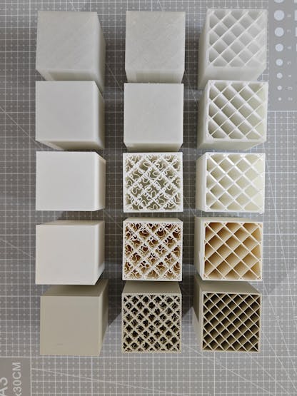
After meticulously printing the three cubes showcasing different surface defect stages with each filament, I produced all plastic objects (15 in total) required to construct an extensive dataset to train a visual anomaly detection model and develop my industrial-grade proof-of-concept surface defect detection mechanism.
![]()
![]()
![]()
![]()
![]()
![]()
![]()
![]()
![]()
![]()
![]()
-
3Continue reading the full project tutorial
AI-driven Plastic Surface Defect Detection via UV
Experimenting with different UV wavelengths and camera types to develop a feature-rich industrial anomaly detection mechanism with edge AI.


Discussions
Become a Hackaday.io Member
Create an account to leave a comment. Already have an account? Log In.