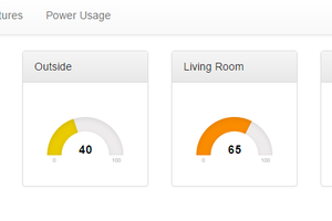
• How I did it

    RobG15 hours ago 0 comments

    Some photos of the stock machine, showing the bracket mounted on the right: 

    View from above - bracket circled in red
    View from above - bracket circled in red
    View from front - bracket circled in red
    View from front - bracket circled in red

    After designing and making a new bracket from angle aluminium (see supplied STEP file) I was able to relocate the sensor to the left/chuck side using a pair of M6 tapped holes that were already present in the saddle. I'm not sure what they were originally for, but no-one was using them!

    Adjustment of the sensor position can be made by including shims or spacers (in my case 3mm brass tube slipped over the screws). The magnetic strip itself can be bought online cheaply but I was able to carefully remove and reuse the strip from the original bracket using a bit of heat and a thin blade.

    The next photos show the new sensor assembly: 

    The installed sensor assembly
    The installed sensor assembly
    The sensor assembly with the cover off
    The sensor assembly with the cover off

    A simple cover keeps the majority of the swarf out. It is made from thin aluminium sheet, cut and folded and secured with M4 CSK screws into the existing tapped holes in the sensor.