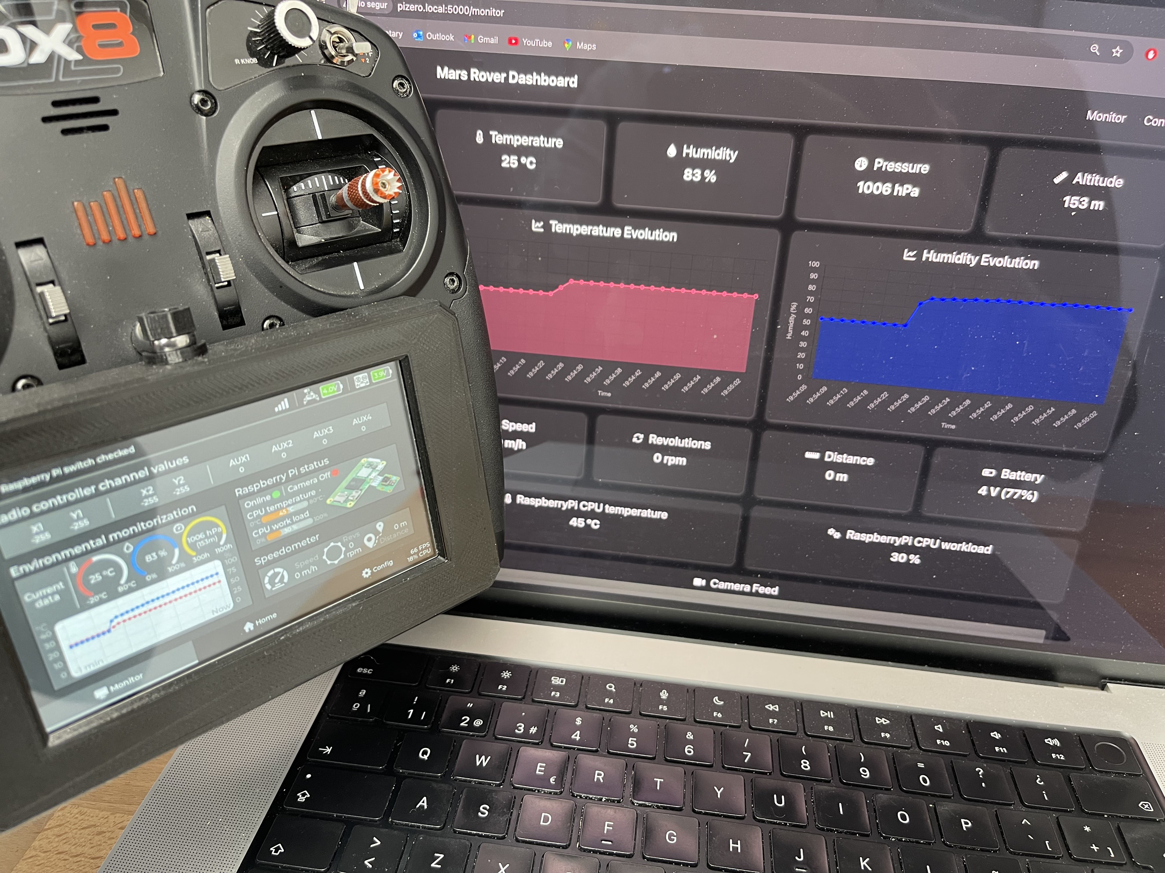
Close
0%
0%

Rover Robotic Platform - Arduino/ESP32/RaspberryPi

3D-printed robotic platform inspired by NASA’s Perseverance Mars Rover. It incorporates Raspberry Pi, ESP32, and Arduino development boards

Public Chat
Similar projects worth following
Rovers are planetary surface exploration robots that space agencies like NASA send to Mars to explore the planet. In this project, a functional 3D printed replica of the "Perseverance" rover, which was launched by NASA in July 2020, is created.

The project is named OpenRover. Although some open-source robotic projects related to Mars rovers already exist, they tend to use a single type of development board. In the OpenRover project, several development boards are used among its main functional modules (e.g., RaspberryPi for web connectivity, ESP32 for embedded screen, Arduino for motor control) and there are interactions between these modules. This allows to see some of the optimal usecases for each development board.

As rovers are extremely sophisticated machines, they provide the perfect excuse to incorporate into the robotic platform several complex functionalities that replicate those that real Mars rovers have (e.g., robotic arm, environmental sensors, 360º turns, camera).

Features

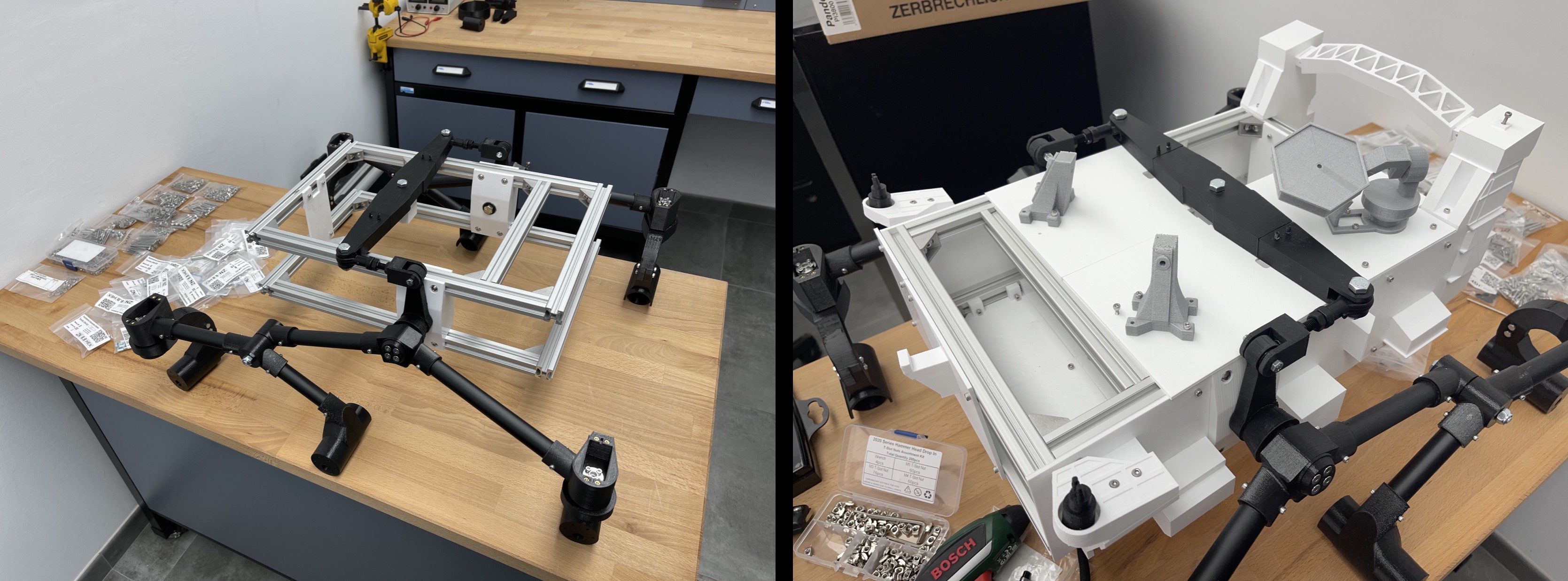
  • 6-wheel drive platform with 4 steerable wheels
  • 4-axis foldable robotic arm with gripper
  • Tiltable and rotary head, with space for a development board and a camera
  • Environmental sensors to measure temperature, humidity, pressure and altitude
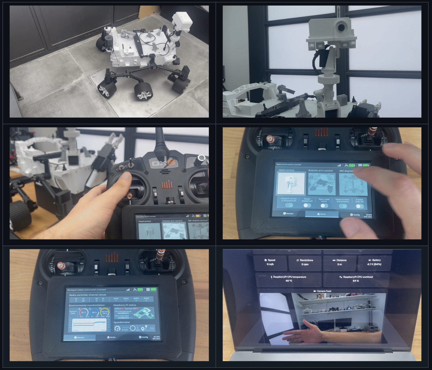
  • Custom remote control module with touchscreen, with a UI where status values are displayed and different operation modes can be selected
  • Battery sensors for the rover and the custom remote control
  • 4 main operation modes: conventional driving control, 360º turn control, robotic arm control, head control
  • Web dashboard that displays status values and a video feed. This web dashboard is hosted in the rover


Project modules

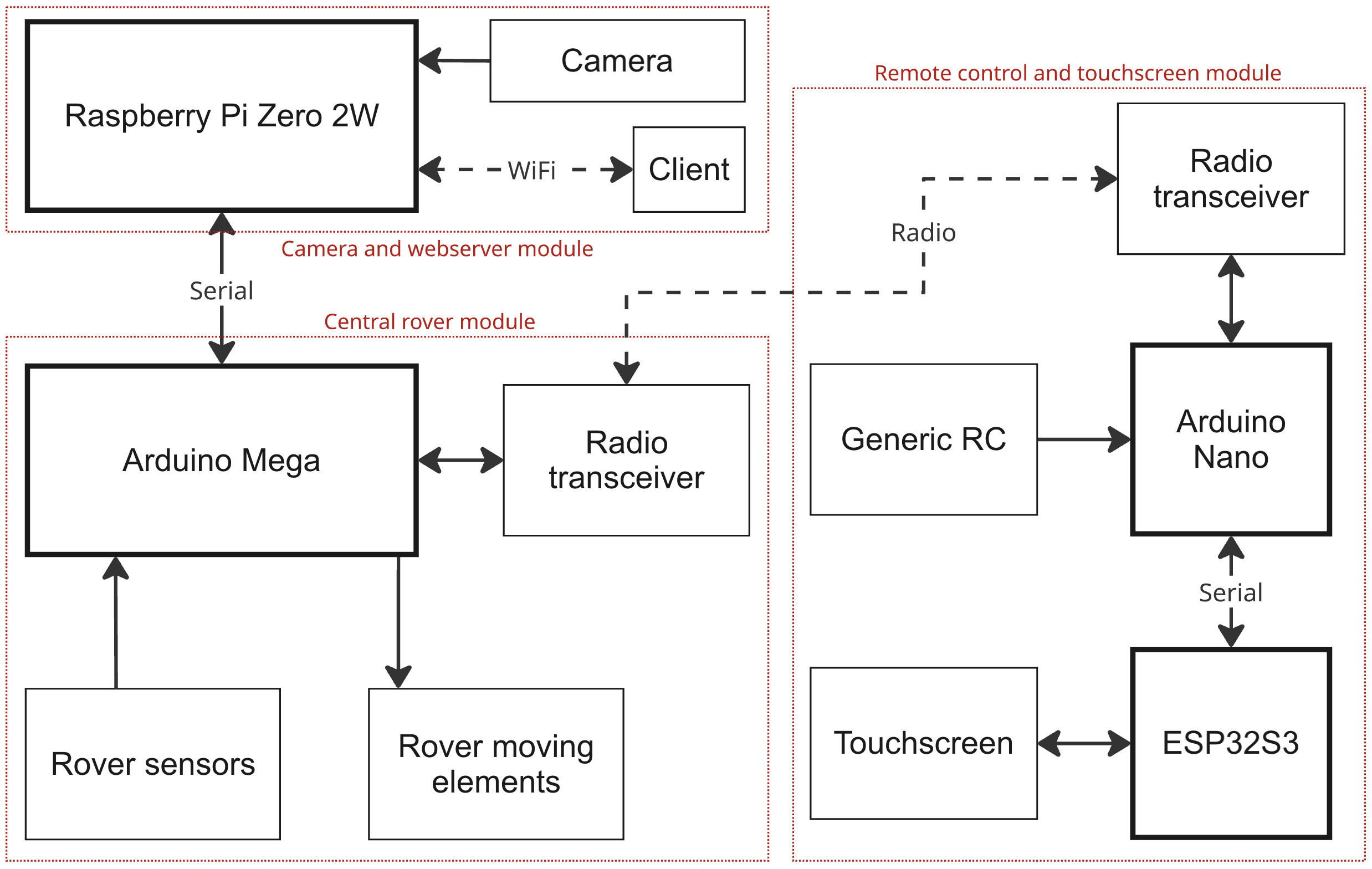
The OpenRover's components are organized, both at a hardware and software level, in different modules:

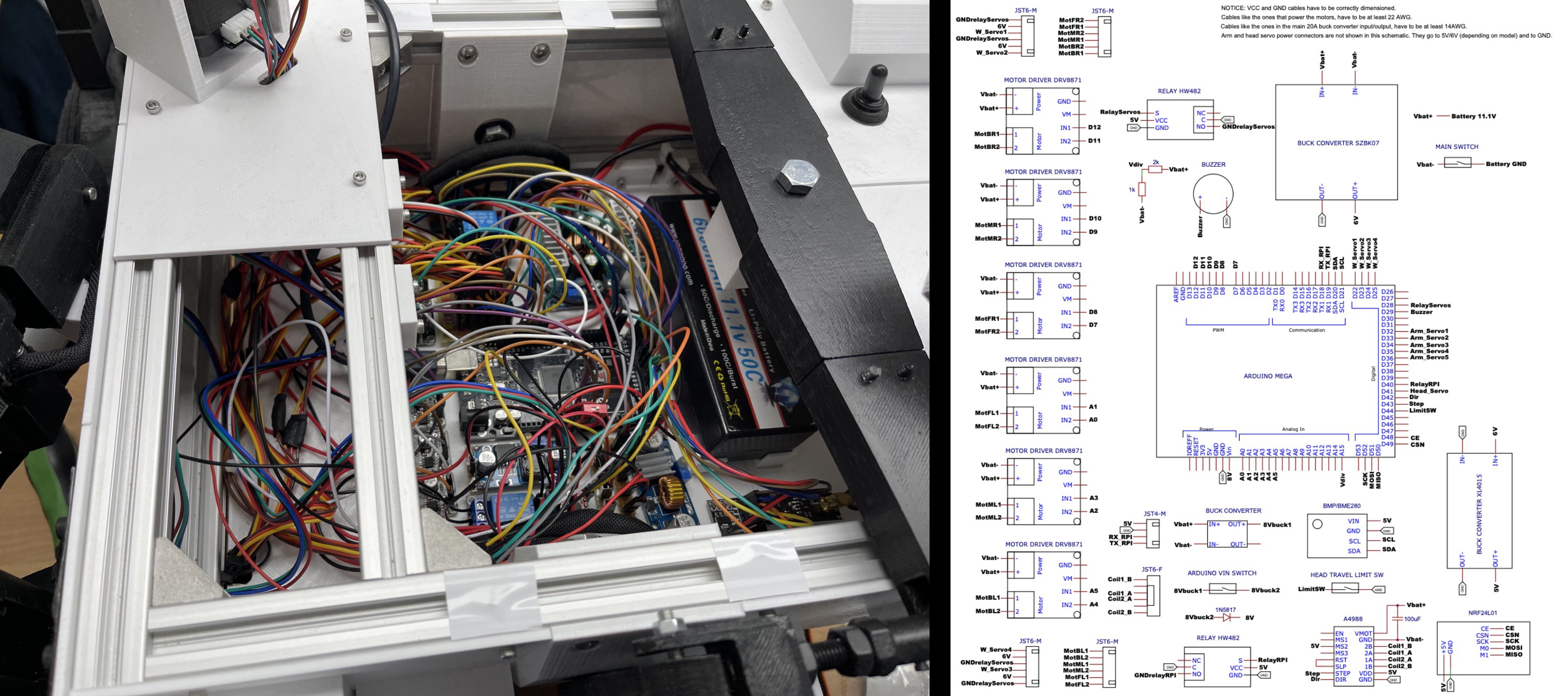
  • Central rover module: It has an Arduino Mega development board that is inside the main body of the rover and that manages all moving elements (e.g., motors, servomotors) as well as the rover's sensors and sending/receiving the radio signal
  • Remote control and touchscreen module: It has an ESP32S3 development board that is responsible for the touchscreen, and an Arduino Nano that is responsible for reading the RC channel values, sending/receiving the radio signal and measuring battery levels
  • Camera and webserver module: It has a RaspberryPi Zero 2W development board that is inside the head of the rover. This board connects to a camera, generates a WiFi network and hosts a web dashboard


Tech stack

Programming languages and frameworks

Other technologies

To program Arduino and ESP32 microcontrollers, the PlatformIO IDE with the Arduino Framework was used. To create the embedded UI design of the touchscreen, the SquareLine Studio platform and LVGL library were used.


GitHub repository

This is the original GitHub repository of the OpenRover project:

https://github.com/pol-valero/openrover-robotic-platform

The GitHub repository can be used to complement this project guide, since it contains designs, schematics, documentation and the most up-to-date source code.


Disclaimers

The rover's 3D design was originally made by a mechatronics engineer called Dejan, who owns an educational YouTube channel and website called "HowToMechatronics". This design was adapted and improved.

Link to the original project used for the rover's 3D design

The robotic arm's 3D design was extracted from a GitHub project made by Jakob Krantz, who also created a Mars rover replica. This design was adapted and improved.

Link to the original project used for the robotic arm's 3D design

All the OpenRover hardware and software was created from scratch, following a different approach from the one the creators of the original 3D designs followed.


Demos

See some demos of the rover, custom remote control and monitoring web dashboard here: https://github.com/pol-valero/openrover-robotic-platform/tree/main?tab=readme-ov-file#demos
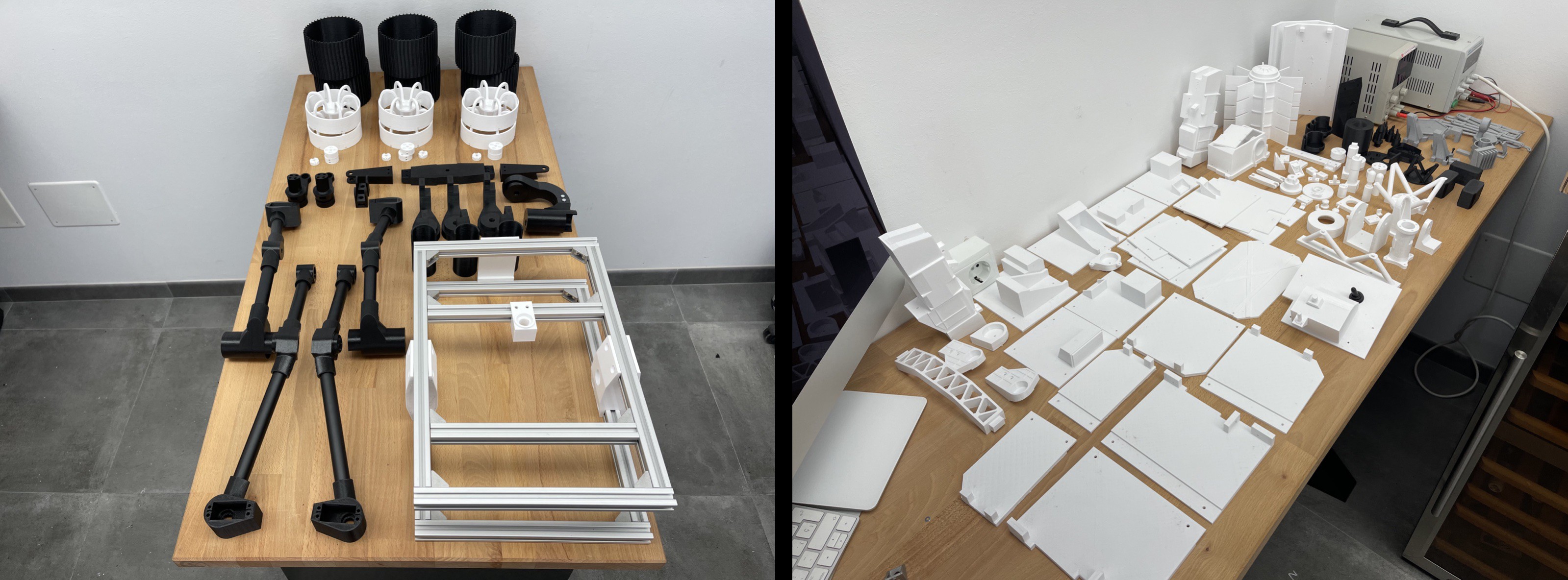

Components

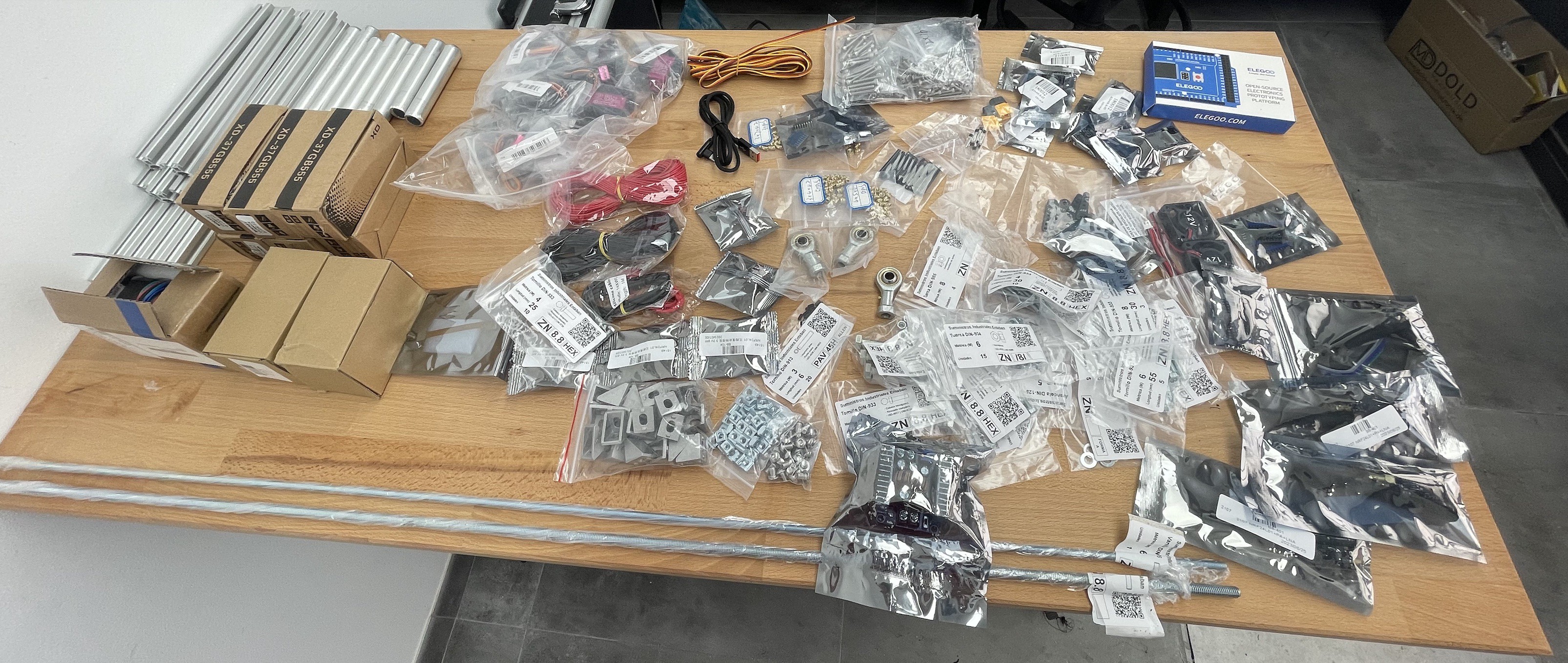
A list with some mechanical components needed for the rover can be found in the website of the original project used for the rover's 3D design. The rest of the mechanical and hardware components will be detailed in the next Components section. 

The hardware and mechanical components were purchased on Aliexpress, but most of them are also available on Amazon.

central_rover_module_schematic.pdf

Adobe Portable Document Format - 67.08 kB - 01/21/2026 at 10:01

Preview

rc_and_touchscreen_module_schematic.pdf

Adobe Portable Document Format - 31.69 kB - 01/21/2026 at 10:01

Preview

camera_and_webserver_module_schematic.pdf

Adobe Portable Document Format - 19.41 kB - 01/21/2026 at 10:01

Preview

  • 1 × NEMA17 stepper motor
  • 1 × Toggle switch 20A
  • 2 × SS-12D10 switch
  • 1 × Arduino Mega
  • 10 × MG996R/DS3225 servo

View all 45 components

  • 1
    3D print all the parts

    Open the designs in the Fusion360 app and export each of the components to a STL format so they can be send to the Slicer and printed. 

    The original design of the Mars rover model can be found in this Cults3D page. The original design of the robotic arm can be found in this GitHub page. Lots of modifications were made to these designs, which were originally created by Dejan (HowToMechatronics) and Jakob Krantz respectively.

    Since the original design of the Mars rover is not free (it has to be purchased via the Cults3D page provided before) only the parts of the rover that were created from scratch are present in the rover_modified_and_new_parts.f3d design file. 

    Since the original design of the robotic arm is open-source, the rover_modified_and_new_parts.f3d design file contains the parts of the robotic arm that were either created from scratch, modified or original.

    The cases for the custom remote control PCB module and ESP32S3-8048 touchscreen are in this Fusion360 design file. These cases adapt to the shape of the Spektrum DX8 remote, allowing to place the custom RC module and touchscreen as add-ons.

    The case for the ESP32S3-8048 touchscreen is a modified version of this case design found on Thingiverse.

  • 2
    Assemble the mechanical platform

    Assemble the mechanical platform by joining the different 3D printed parts with the other mechanical parts (e.g., pvc tubes, aluminium profiles). A detailed guide for the mechanical assembly process is available in the original project used for the mechanical design.

    Images showing how the OpenRover modified design was assembled are present in the README of the assembly folder of the OpenRover GitHub project.

  • 3
    Place hardware components and create wiring connections

    Create the wiring connections for the hardware components (e.g., motors, servomotors) and between the hardware electronics (e.g., Arduino Mega, motor drivers).

    To help with the wiring connections, one schematic is provided for each of the modules of the OpenRover project (central roverremote control and touchscreen, and camera and webserver)

    Images showing the soldering of various boards, the creation of electrical connections, and the placement of hardware components can be found in the README of the assembly folder.

View all 5 instructions

Enjoy this project?

Share

Discussions

Does this project spark your interest?

Become a member to follow this project and never miss any updates