 Pol Valero
-
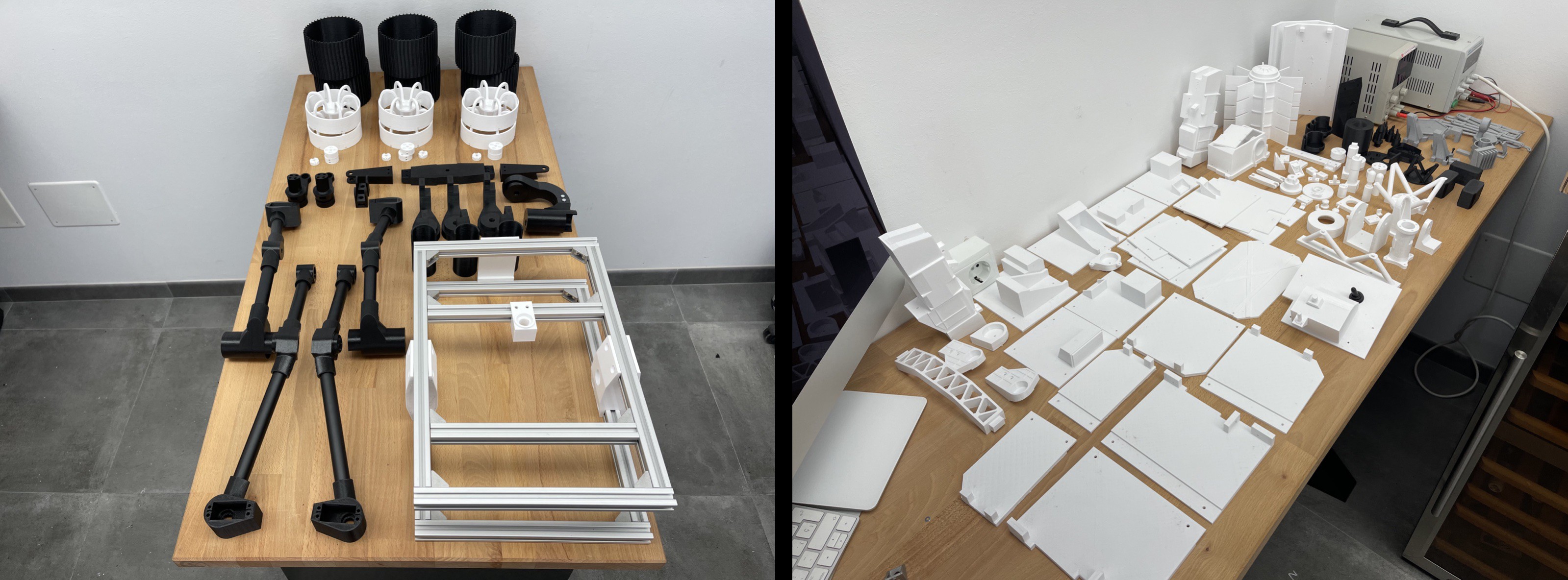
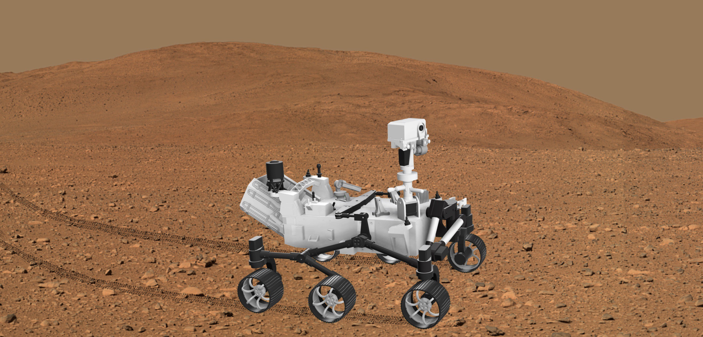
13D print all the parts
![]()
Open the designs in the Fusion360 app and export each of the components to a STL format so they can be send to the Slicer and printed.
The original design of the Mars rover model can be found in this Cults3D page. The original design of the robotic arm can be found in this GitHub page. Lots of modifications were made to these designs, which were originally created by Dejan (HowToMechatronics) and Jakob Krantz respectively.
Since the original design of the Mars rover is not free (it has to be purchased via the Cults3D page provided before) only the parts of the rover that were created from scratch are present in the rover_modified_and_new_parts.f3d design file.
Since the original design of the robotic arm is open-source, the rover_modified_and_new_parts.f3d design file contains the parts of the robotic arm that were either created from scratch, modified or original.
The cases for the custom remote control PCB module and ESP32S3-8048 touchscreen are in this Fusion360 design file. These cases adapt to the shape of the Spektrum DX8 remote, allowing to place the custom RC module and touchscreen as add-ons.
The case for the ESP32S3-8048 touchscreen is a modified version of this case design found on Thingiverse.
-
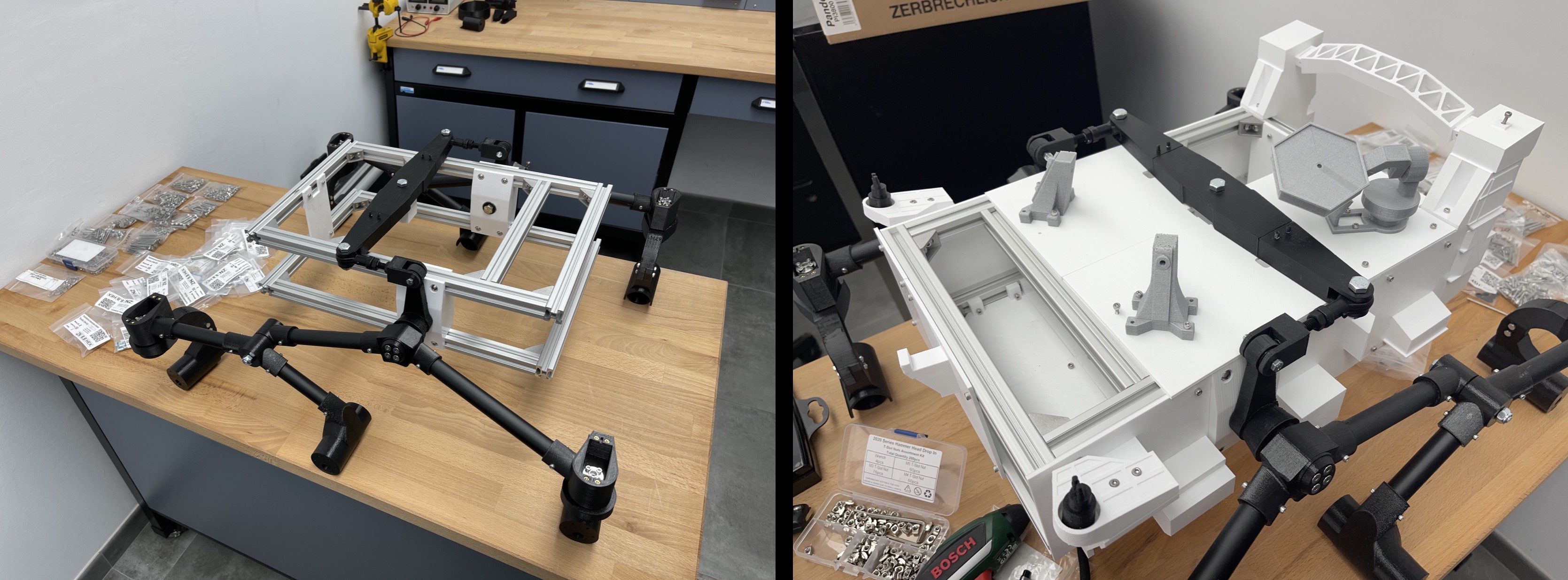
2Assemble the mechanical platform
![]()
Assemble the mechanical platform by joining the different 3D printed parts with the other mechanical parts (e.g., pvc tubes, aluminium profiles). A detailed guide for the mechanical assembly process is available in the original project used for the mechanical design.
Images showing how the OpenRover modified design was assembled are present in the README of the assembly folder of the OpenRover GitHub project.
-
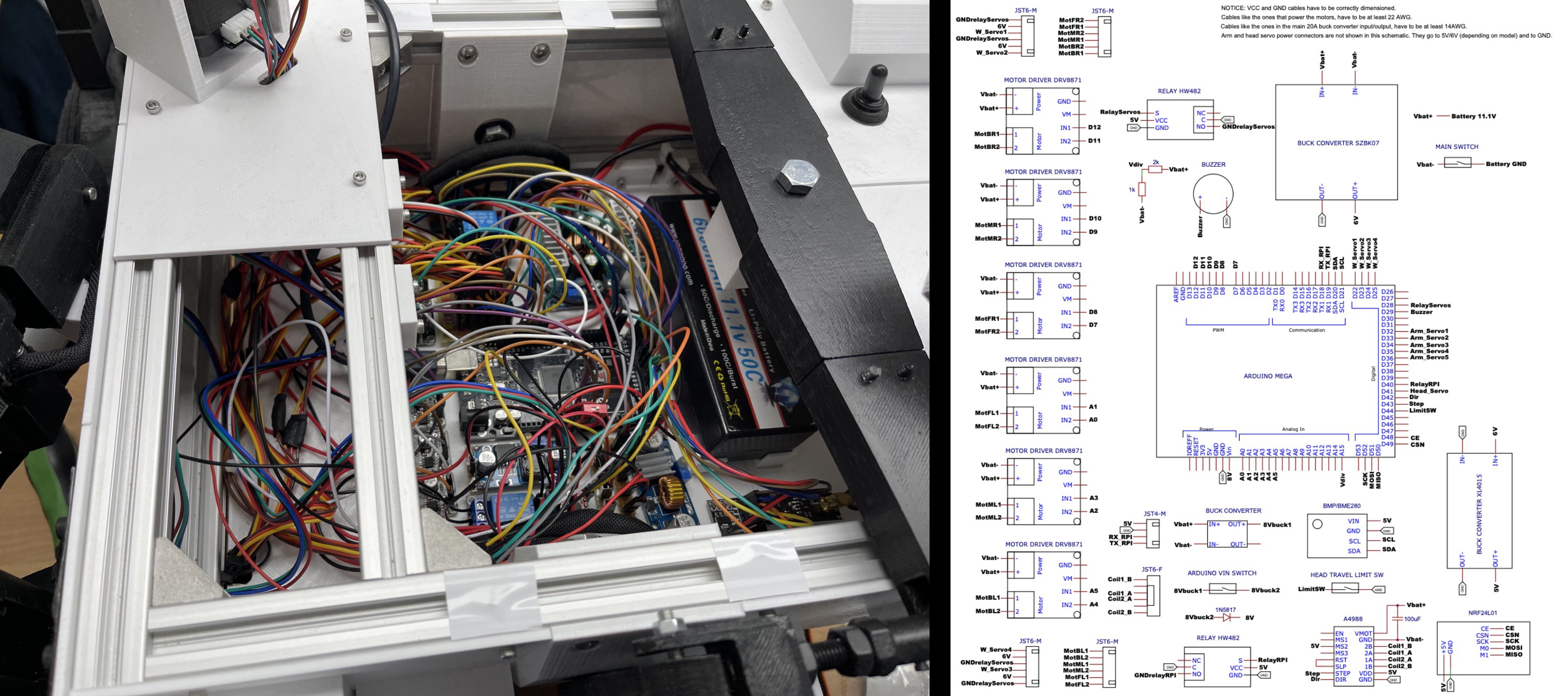
3Place hardware components and create wiring connections
![]()
Create the wiring connections for the hardware components (e.g., motors, servomotors) and between the hardware electronics (e.g., Arduino Mega, motor drivers).
To help with the wiring connections, one schematic is provided for each of the modules of the OpenRover project (central rover, remote control and touchscreen, and camera and webserver)
Images showing the soldering of various boards, the creation of electrical connections, and the placement of hardware components can be found in the README of the assembly folder.
-
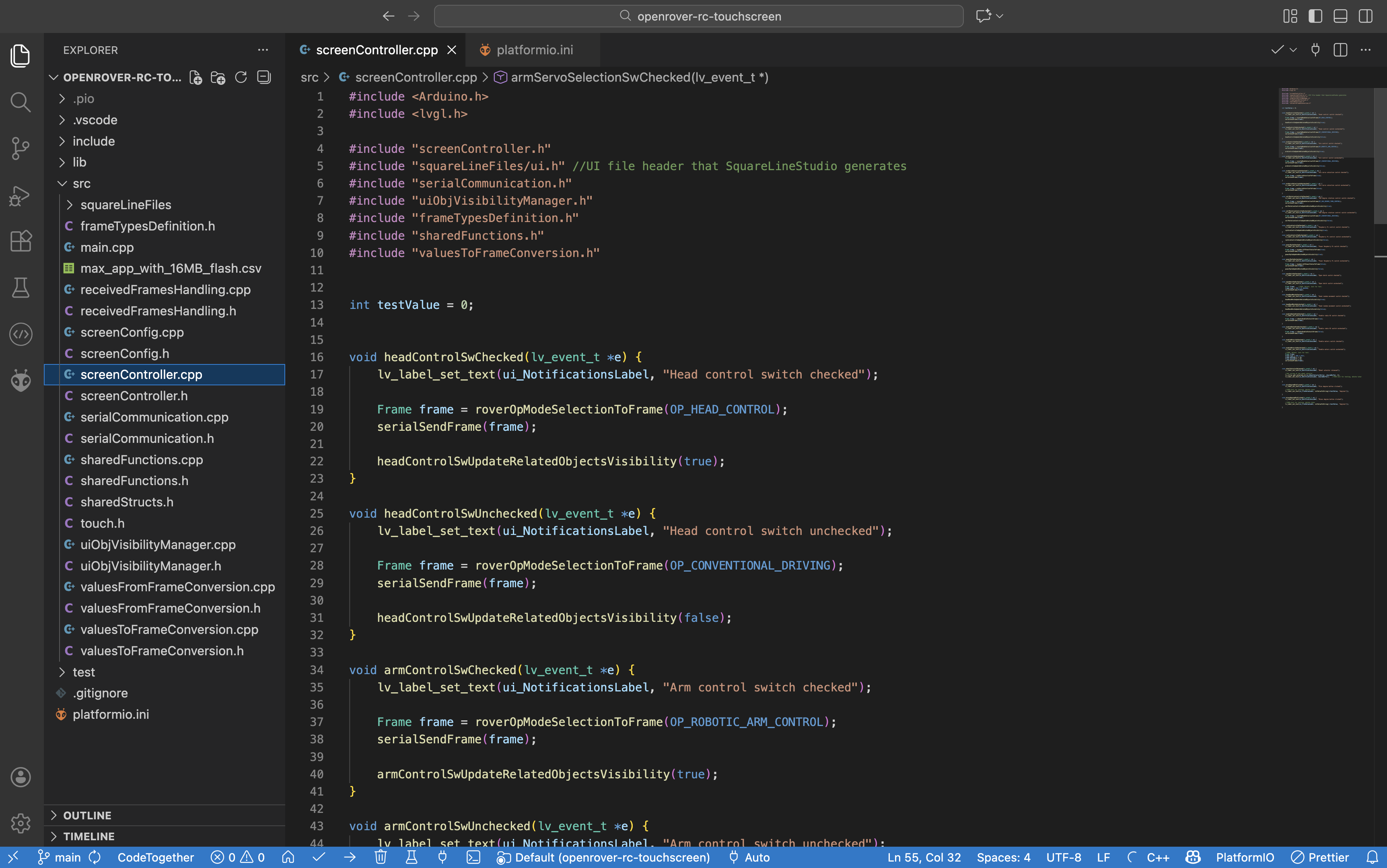
4Upload code to development boards
![]()
For each of the OpenRover modules, set up and upload the code to the development boards.
To develop the code for the modules, PlatformIO IDE was used. This IDE is integrated into the versatile Visual Studio Code editor, and can be installed simply by searching "PlatformIO IDE" in the "Extensions" tab of Visual Studio Code.
Thanks to the use of PlatformIO, all the code, configuration files, and dependencies are in a single package. This makes it very easy to share the complete project, enabling other people to execute it right after they download it.
Since the code is modulated and quite long, no preview of the code will be shown here. Instead, links to the coding projects present in the OpenRover GitHub repository will be provided in this section.
Central rover module
Just by opening the project present in this folder with PlatformIO, connecting the Arduino Mega development board via USB, and clicking the "upload" button, the code will be uploaded to the Arduino Mega and will start executing.
The only thing that needs to be taken into account is making sure that the wiring connections to the Arduino Mega are exactly the same as the ones detailed in the wiring schematic of this module.
Remote control and touchscreen module
Remarks
The developed remote control and touchscreen module is currently an add-on to any generic RC that has a PPM output port (usually known as "Trainer Port"). The RC model that I have personally used is the Spektrum DX8.
This trainer port usually is a 3.5mm audio jack, but it is not a standard port and can also be a mini-USB, depending on the brand. The transmitters usually use PPM (Pulse Position Modulation) signals outputted from this “Trainer port” to transmit each of the RC channel values.
With the help of an Arduino Nano, these PPM signals are processed by the custom RC module of the OpenRover project. This way, the radio module of the generic RC is not used, and the only purpose of the generic RC is to send the values of its different channels (e.g., joysticks, switches…) via PPM, so that the custom RC module can receive them. In turn, this custom module uses an NRF24 radio transceiver to send the channel values to the rover using a custom communication protocol.
If instead of a generic RC, a custom RC with joysticks and switches wanted to be used, the Arduino Nano would directly read the values of these joysticks and switches instead of the PPM channel values. This adaptation would require very few modifications on the developed OpenRover hardware and software for this remote control and touchscreen module.
Code setup guide
This module is formed by two submodules, the "Arduino Nano" and the "ESP32S3 touchscreen" submodules.
Each of the two submodules is a standalone PlatformIO project. Therefore, just by opening each PlatformIO project present in this folder, connecting the ESP32S3 or Arduino Nano development board via USB, and clicking the "upload" button, the code will be uploaded to the ESP32S3 or Arduino Nano and will start executing.
The only thing that needs to be taken into account is making sure that the wiring connections of the ESP32S3 and the Arduino Nano are exactly the same as the ones detailed in the wiring schematics of this module.
Embedded UI design
To create the embedded UI design of the touchscreen, the SquareLine Studio platform and LVGL library were used. To edit the UI, these steps have to be followed:
- Step 1: Open the SquareLine Studio project and make the desired visual changes
- Step 2: Click on Export -> Export UI Files. The UI files export path must be previously specified in the "Project Settings"
- Step 3: Copy all the exported UI Files into the "squareLineFiles" folder of the ESP32S3 PlatformIO project, making sure to overwrite the previous files that were in this folder
- Step 4: Click the "upload" button in PlatformIO to upload the code to the ESP32S3. The modified UI should now appear on the touchscreen.
Three screens have been implemented in the embedded UI: Control, Monitor and Configuration.
Camera and webserver module
Before uploading this module's project code in the RaspberryPi Zero 2W, it is necessary to install and OS in the board. Specifically, the RaspberryPi OS Lite (headless version) has to be installed. This OS and an install guide can be found in the RaspberryPi website.
Once the Raspberry Pi OS is running and SSH connections can be made to be the board, it is possible to upload all the module's project code. Here is the module's project code that needs to be uploaded to the Raspberry Pi. To upload an edit the code, the best way is to install the SFTP plugin for the Visual Studio Code editor. This plugin allows to easily set up and modify the project’s file structure and file’s contents remotely from a standard PC.
Once the whole project is uploaded, you have to go inside the main project folder and execute the following command: python -m logic.main
If it is the first time you execute this command, several errors will displayed, detailing the dependencies used by the code that need to be installed. It is recommended to install this dependencies on a "virtual environment". Once these dependencies are installed, if we execute the previous command, this module's program will start running, stablishing serial communication with the Arduino Mega and generating the web dashboard.
The web dashboard will be available on the following URL: http://pizero.local:5000/monitor
If instead of the RaspberryPi connecting to an existing WiFi, you want the RaspberryPi to generate a WiFi network on its own, the following command needs to be used: sudo nmcli device wifi hotspot ssid RoverWiFi password marsRover
Optionally, the commands to generate the WiFi network and to execute the module's program can be written into a script. This script can then be called inside the /etc/rc.local file, which is executed at startup. This way, once the RaspberryPi Zero 2W is powered, it will generate the WiFi network and execute the module's program automatically. You can find and example startup script in the raspberrypi_code/scripts/ folder.
It is important to make sure that the wiring connections to the RaspberryPi Zero 2W are exactly the same as the ones detailed in the wiring schematic of this module.
-
5Take it to the next level
![]()
Now it is your time to build upon the OpenRover platform. One of the cores ideas behind OpenRover is that people who replicate the project are able to modify and improve the platform, as it is designed to be very modular and extensible, specially on the software related side.
You can add your own upgrades to the robot, integrating new components and developing additional features.
Here are some ideas to spark inspiration for expanding OpenRover's functionalities:
- Rover control from the web dashboard (e.g., using draggable joysticks), which currently is only used for monitoring and displaying video feed
- Adding computer vision using the existing RaspberryPi camera and RaspberryPi Zero 2W board. Computer vision could be used to navigate autonomously or to track objects with the rover's tiltable and rotary head
- Ability to record movements for the robotic arm, allowing it to automatically fold and unfold or perform a certain procedure
- From the hardware schematic designs, design PCB boards that can be manufactured. These boards would be very useful to make the hardware connections more compact and to allow an easier replication of the project
Mars Rover Robot - Arduino/ESP32/RaspberryPi
3D-printed robotic platform inspired by NASA’s Perseverance Mars Rover. It incorporates Raspberry Pi, ESP32, and Arduino development boards
Discussions
Become a Hackaday.io Member
Create an account to leave a comment. Already have an account? Log In.