 Profe Tolocka
Anatomy of an EPD
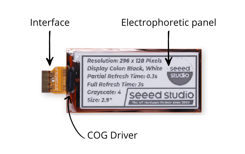
In the previous part of this tutorial, we identified the main components of an EPD screen: the top electrode, the film containing the microcapsules, and the bottom electrode or TFT matrix. These elements together form what we call the electrophoretic panel or EPD matrix, which is essentially the heart of the display since it contains all the visual elements.
Let’s now take a closer look at the anatomy of an EPD.
Electrophoretic Panel
The electrophoretic panel is like a sandwich made up of several very thin layers:
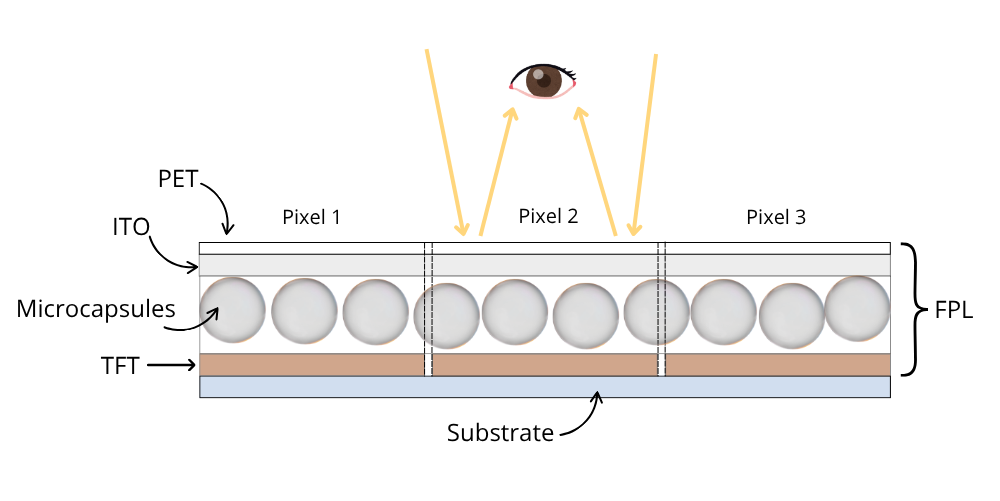
On the front of the EPD panel, there is a protective layer of transparent plastic (PET - Polyethylene Terephthalate), followed by a transparent conductive oxide electrode (ITO - Indium Tin Oxide).
Beneath this lies the film with the microcapsules and the pixel electrode matrix (TFT). Together, these layers form the FPL (Front Plane Laminate), which is laminated onto a rigid or flexible substrate during manufacturing.
Driver
The EPD panel itself doesn’t include the electronics needed to generate images, so a driver chip is integrated to act as the “brain” of the system, generating the electrical signals that move the pigments.
This driver is usually mounted directly onto the panel using COG (Chip On Glass) technology, which is why it’s also known as a COG driver. Some of the most commonly used drivers are the SSD1680, UC8179, and JD79661.
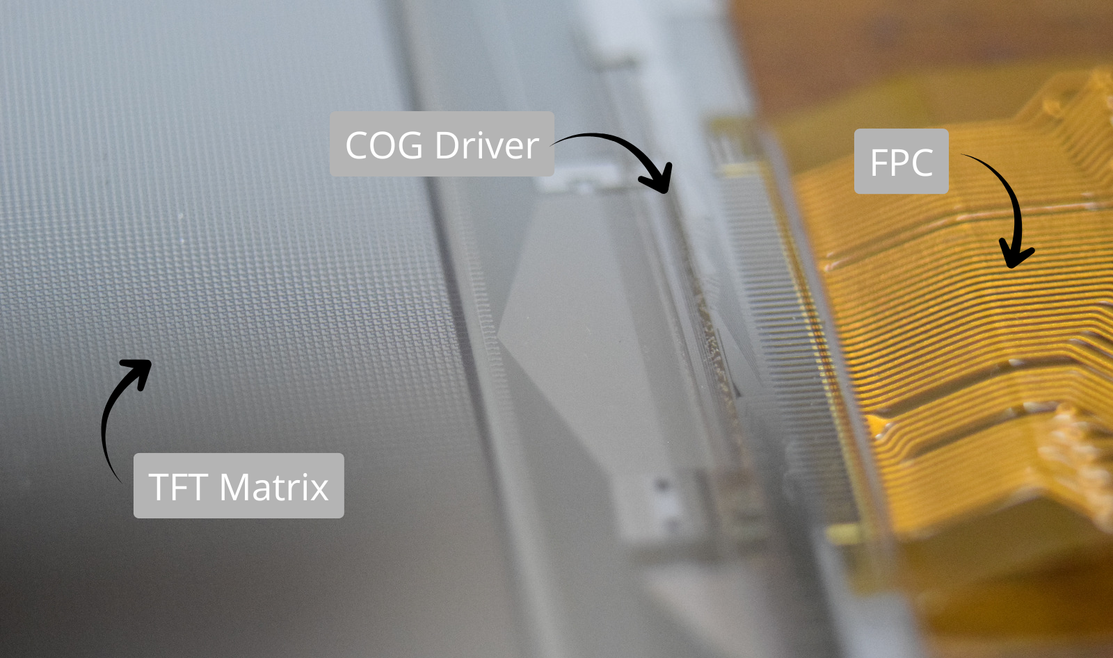
Back side of an EPD showing the TFT matrix, the COG driver, and the FPC connector
TFT Matrix
The TFT matrix organizes the pixel electrodes in rows and columns, with each electrode controlled by a thin-film transistor.
The transistors share the GATE line across each row and the SOURCE line across each column, while the drain is connected to each pixel. Inside the driver chip, the Gate Driver circuit controls the rows, the Source Driver controls the columns, and a third block manages the upper common electrode called VCOM.
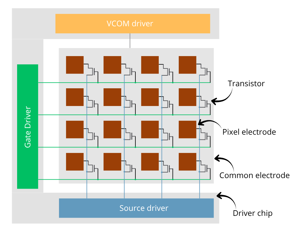
This arrangement allows each pixel to be individually addressed and the necessary voltages to be applied to achieve the desired color. Each electrode defines a pixel, which is actually made up of multiple smaller microcapsules — responsible for the granular appearance of the panel when viewed under magnification.
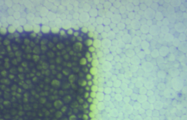
Granular pixel detail in an EPD
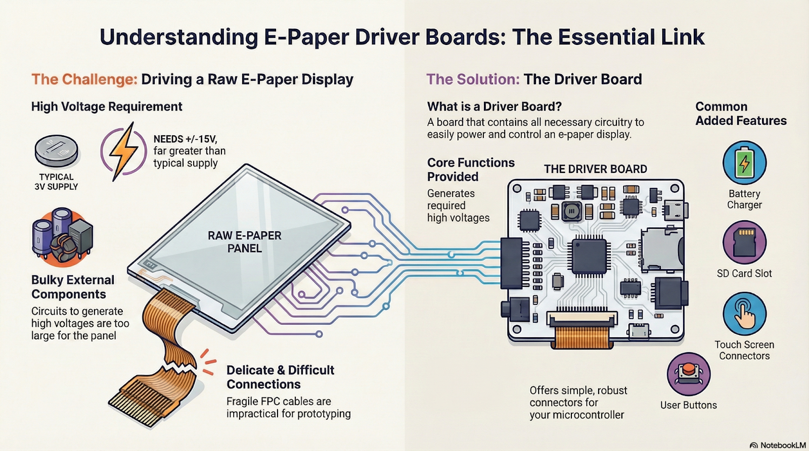
The driver controls the TFT matrix, but it receives data and instructions from an external controller board via an interface.
This interface can be serial (SPI or I²C) or parallel, and in addition to the data lines, it also includes power and control pins, so the total number of connections is often quite high.
Driver Boards
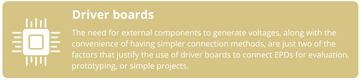
EPD screens require high voltages (both positive and negative) to move the pigments, which the driver chip generates from a low-voltage supply using charge pumps or DC-DC converters. These circuits need external components that can’t be integrated into the panel itself. Additionally, connecting via FPC is delicate and not very practical for prototyping.
For these reasons, driver boards are used. They handle the generation of panel voltages and make it easier to connect with a microcontroller. These boards usually offer more convenient connectors and extra features such as battery charging, LEDs, push buttons, or SD card slots.
There are different driver boards available for various types of projects. For example, here are some of the options offered by Seeed Studio — ranging from simple boards ideal for prototyping to more advanced controllers designed for complex applications:
ePaper Breakout Board: This board features a 24-pin FPC connector for attaching the EPD panel, and a socket specifically designed for inserting a XIAO module, which acts as the main controller. It’s compatible with different XIAO models and allows you to control both monochrome and color EPDs of various sizes. [Link]
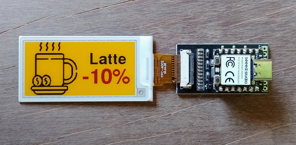
ePaper breakout board with a XIAO RA4M1 controlling a 4-color display
ePaper Driver Board: This...
Read more »
 Sjaak
Sjaak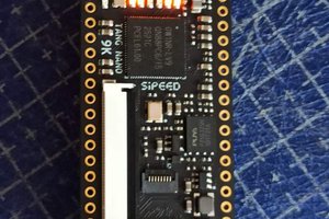
 Pavel
Pavel
 Ace
Ace
 Jared Sanson