 Jared Sanson
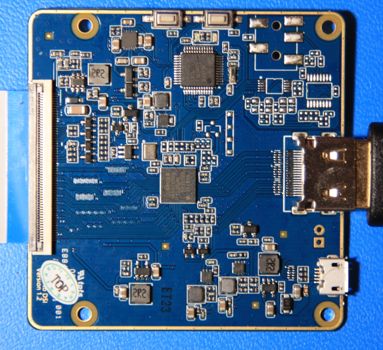
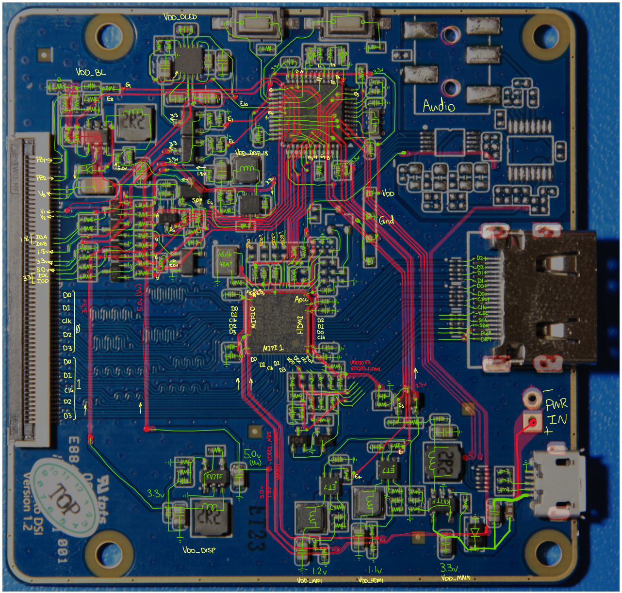
- On the left you can see a large ribbon connector. This allows you to connect a range of different types of display using one or both MIPI channels. It has multiple voltage rails, and bi-directional GPIOs at 1.8 & 3.3V. These are usually used for power-sequencing the display.
- On the right is the HDMI 1.4b connector.
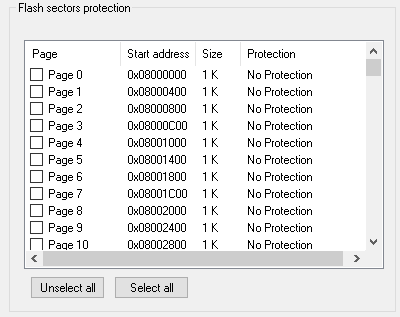
- And at the top is the controlling MCU, which is an STM32 clone. This initializes the bridge chip via I2C.
- There are also some unpopulated pads, which seem to be for an optional I2S audio output.
Each board comes pre-configured for the displays that it comes with, but I have not yet figured out how to reconfigure a board to support an abitrary display. Mine came with support for these interesting round OLEDs, presumably intended for some kind of smartwatch...
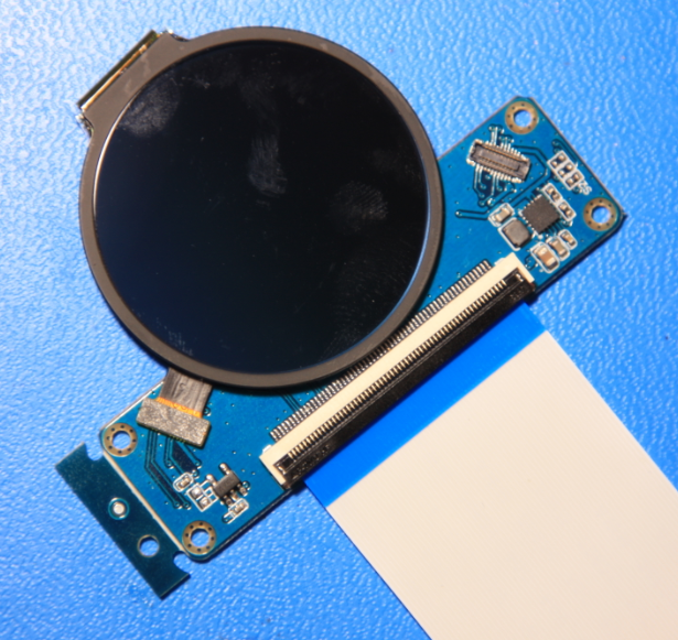
 This consists of a specialized OLED driver chip, a 2.8v LDO, and two OLED connectors that utilize only 1 MIPI data pair on each channel:
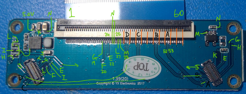
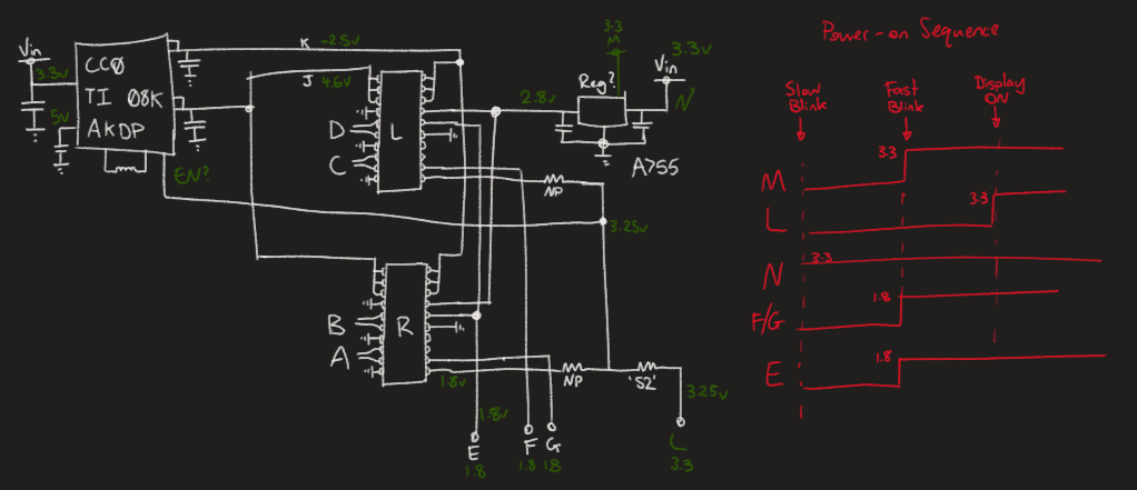 I was unable to find a datasheet for my specific displays, but I determined the pinout for each display is roughly:
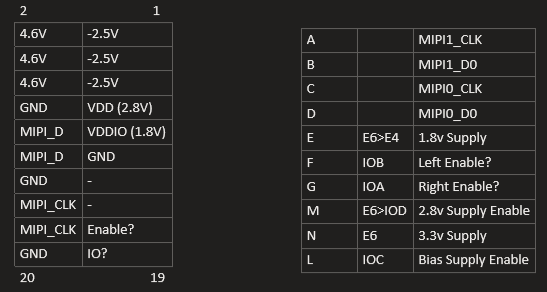
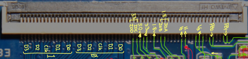 The connector provides two independent MIPI channels, each with 4 data pairs & 1 clock pair. The 5V rail is always powered, but the other rails can be individually sequenced and controlled by the MCU. The GPIOs can be used to control additional regulators or enable control signals on the display board. They are output only.
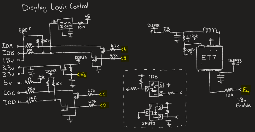


 Bharbour
 Arnov Sharma
 Ken Yap
somebody still programing this board ???