 Silícios Lab
Introduction and Objective
The Problem
In the development of electronic monitoring systems, we often encounter a lack of devices that integrate precise reading and direct actuation. Industrial sensors are usually expensive and require complex PLCs. The need here was to create a compact and connected device capable of monitoring pressure in real time and reacting instantly to variations, without relying exclusively on the cloud for critical decisions, while maintaining remote supervision.
The Solution
The project consists of an intelligent control node based on the ESP32, using the MPS20N0040D-D piezoresistive sensor. The board not only reads the pressure and processes the data locally to manage a load via relay (such as valves or pumps), but also uses the power of the ESP32 SoC to overcome the physical barrier. Thanks to native Wi-Fi connectivity, pressure data is sent to the web, allowing industrial or residential processes to be monitored in real time from anywhere in the world through dashboards or applications.

Would you like to download the files and receive 5 printed circuit boards for this project? Access this link, create your PCBWay account, and download them now from our repository. Use the coupon and receive 5 free units delivered to your home.
The objective of this article is to present the complete solution for this electronic board, which was designed for pressure monitoring in various processes.
Throughout this text, we will detail the operation of each circuit on the board, from analog signal conditioning to power output protection.
Curious about how we transform millivolt signals into web-ready digital data? Follow the next chapter where we detail the Hardware Architecture.
Hardware Architecture and Electronic Schematic
Now we will detail how each component was integrated to ensure that the raw signal from the sensor is transformed into reliable information for the microcontroller and, subsequently, for the web.
The MPS20N0040D-D Sensor
The heart of the measurement is the MPS20N0040D-D sensor, which uses piezoresistive technology in a Wheatstone Bridge configuration.
,See the MPS20N0040D-D in figure below.

The major challenge here is its sensitivity: the output is a differential signal of very low amplitude (only a few millivolts). Without proper processing, any electrical noise would make the reading unstable, preventing accurate monitoring of industrial processes.
The ESP32 Microcontroller
We chose the ESP32 not only for its low cost, but also for its ecosystem. With two processing cores, it can read the sensor on one core while managing the Wi-Fi connection and data transmission to the web on the other. This prevents the network process from freezing or delaying pressure readings, ensuring true real-time monitoring.
Output Peripherals and Interface
The board was designed to be self-sufficient in the field:
Actuation Relay: Allows the board to interrupt or start a process (such as shutting down a compressor) as soon as a pressure limit is reached, acting as a local safety system.
Audiovisual Signaling: The buzzer and LED provide instant feedback to the operator. In IoT systems, local feedback is as important as remote feedback; the operator needs to know the system status even if the Wi-Fi network goes down.
Control Buttons: Allow interactions such as "tare" (resetting) the sensor or switching between manual and automatic operating modes.
Next, we will present the electronic schematic of the printed circuit board design.
Electronic Schematic
Below, we present all the blocks of the electronic circuit diagram.


One of the cornerstones of reliable hardware is its power management system. For this board, we designed a 12V VDC ~ 24 VDC input, a common voltage in industrial and automotive environments, which facilitates the integration of the project into real-world scenarios. However, to power the microcontroller and sensors, we need lower and very stable voltages.

The Strategic Role of the LM2596
The first regulation stage uses the LM2596, a Buck Converter (step-down) regulator that reduces the 12V VDC ~ 24 VDC input to 5V. The choice of a switched regulator instead of a linear one (like the 7805) is fundamental for two reasons
- Higher Current Supply: The LM2596 is capable of supplying up to 3A, which ensures that the board has enough current to drive the relay, buzzer, and LED simultaneously, without voltage drops.
- Thermal Efficiency: Unlike linear regulators that dissipate excess voltage as heat, the LM2596 operates in a switched manner, keeping the board cool and increasing the lifespan of components, even under maximum load.
Galvanic Isolation and Noise Immunity with the B0505S
In projects involving highly sensitive sensors (such as the MPS20N0040D-D) and power actuators (such as the relay), electrical noise is the biggest enemy of precision. To solve this problem, we implemented a galvanic isolation stage using the isolated DC-DC converter B0505S.
Why isolate the Ground?
The B0505S receives the regulated +5V and delivers +5V at the output, but with a crucial characteristic: the output GND is completely isolated from the input GND.
This architecture was chosen to create a clean power "island" for the analog reading circuit. By separating the ground (GND) of the digital/power section (where the ESP8266 and the relay operate) from the ground of the sensitive section (sensor and amplifier), we eliminate ground loops and prevent the inductive peak of the relay from influencing the operation of the ESP8266 chip.
This galvanic isolation also acts as a safety barrier, protecting the most sensitive components against transients that may occur in the main power supply line.
Precision Regulation for the ESP8266 with the AMS1117
After the first stage, 5V powers the relay and buzzer, but the ESP32 and the MPS20N0040D-D sensor operate at 3.3V. For this second stage, we use the AMS1117-3.3 linear regulator.
Receiving 5V and regulating to 3.3V minimizes voltage dropout, allowing the AMS1117 to operate extremely stably and with very low noise. This regulation "cascade" (12V VDC ~ 24 VDC input -> 5V -> 3.3V) creates a protective and filtering barrier, ensuring that the processing core and the sensitive analog reading of the pressure sensor do not suffer interference from the electrical network or the relay switching.
The ESP8266 and the Programming Interface
The heart of the board is the ESP8266. It is responsible for receiving the conditioned signal from the pressure sensor and deciding whether the relay should be activated or whether an alert should be sent to the web.

Programming and Communication Circuit
Unlike commercial development boards (such as the NodeMCU), which already have an integrated USB-Serial converter, we designed this board focusing on efficiency and reducing unnecessary components in the final version. To this end, we implemented a dedicated communication bus:
- Interface Pins (ICSP/Serial Header): We exposed the TX, RX, +3.3V, and GND pins. This interface allows connecting an external USB-Serial adapter (such as the FTDI) only when it is necessary to update the firmware, saving space and power in the final hardware.
- Programming Mode (Bootloader): To allow the chip to accept new code, we included strategic buttons on the board. The Flash button (connected to GPIO0) and the Reset button allow you to manually put the ESP8266 into programming mode, a robust standard for developers seeking total control over the hardware.
System Stability
To ensure that the ESP8266 does not suffer unwanted restarts (the famous Brownout), the circuit has decoupling capacitors near the chip's power supply pins. This is vital because the ESP8266's Wi-Fi radio has current consumption spikes during data transmission to the cloud. With this architecture, we ensure that the pressure reading remains stable even during telemetry transmission.
Power Drive and Signal Isolation for relay and buzzer
To ensure that the ESP8266 operates stably, without suffering from electromagnetic interference (EMI) generated by load switching, the buzzer and relay drive circuit was designed with optical isolation.

Cascade Drive Structure
Both peripherals follow a two-stage drive logic:
- Optical Isolation: The ESP8266 GPIO drives an optocoupler. This means there is no direct electrical connection between the microcontroller and the actuators; the signal is transmitted via light.
- Transistor Switching: The optocoupler, in turn, drives a transistor that acts as a current switch, supporting the load necessary for the operation of the final component.
Differences between the Buzzer and the Relay
- Buzzer Circuit: The signal from the optocoupler saturates the transistor, which closes the buzzer circuit, generating the audible alert according to the firmware logic.
- Relay Circuit: The transistor activates the relay coil, allowing the switching of larger external loads (such as pumps and motors). Here, the isolation is double: optical (by the component) and mechanical (by the physical contacts of the relay).
The Two-Ground Strategy (GND A vs. GND B)
A critical point of this design is the management of voltage references. Thanks to the isolated converter B0505S, we divide the board into two power zones:
Ground A (Power/Supplementary Side): This is the main ground that supplies the Buzzer and the Relay with 5V.
Ground B (Sensor/Processing Side): This is the isolated ground, free from noise generated by mechanical and sound components.
By using Ground A for the buzzer and relay, we ensure that current spikes and inductive noise generated during activation are confined to this circuit. This prevents any oscillation from reaching Ground B, protecting the integrity of the ESP8266 and the accuracy of the analog reading from the pressure sensor.
The Heart of Measurement: MPS20N0040D-D Sensor and HX710B ADC
The accuracy of a pressure monitoring system depends entirely on the quality of the analog signal conversion. For this project, we used the combination of the MPS20N0040D-D sensor with the HX710B conditioning chip. Below we have the electronic schematic circuit with these two electronic components.
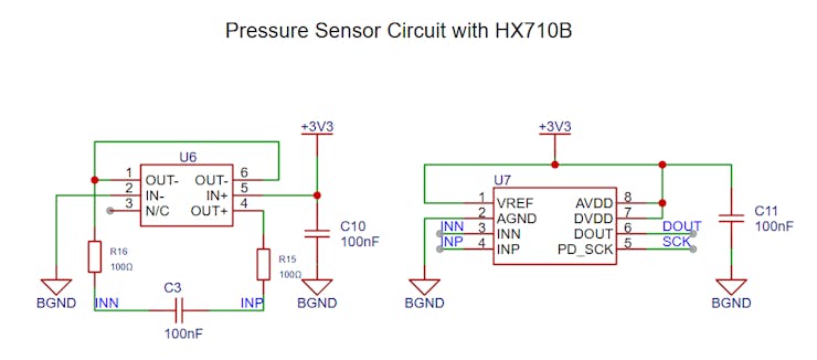
The Piezoresistive Sensor
The MPS20N0040D-D is a sensor based on a Wheatstone bridge. When air exerts pressure on the sensor membrane, the resistance of the internal elements varies, generating a potential difference at the output.
However, this variation is on the microvolt (µV) scale, an extremely fragile signal that cannot be read directly by the standard analog pins of the ESP8266 without a massive loss of resolution and accuracy.
The Precision of the HX710B
This is where the HX710B comes in, a 24-bit Analog-to-Digital Converter (ADC) designed specifically for precision scales and pressure sensors. It solves two critical problems at once:
Low-Noise Amplification (PGA): It has an internal high-gain amplifier that "boosts" the sensor signal to a processable level without adding significant thermal noise.
High Resolution: While the ESP8266's internal ADC only has 10 bits (1024 levels), the HX710B offers 24 bits. This allows it to detect extremely subtle pressure variations, ensuring that web monitoring is faithful to what occurs in the physical process.
Integration and Stability
The HX710B communicates with the ESP8266 through a two-wire interface (Clock and Data), which simplifies the PCB layout. Furthermore, by using the isolated power supply from our B0505S module, the HX710B operates in a "silent" electrical environment, which is crucial to prevent the 24-bit signal from fluctuating due to the Wi-Fi radio's current consumption.
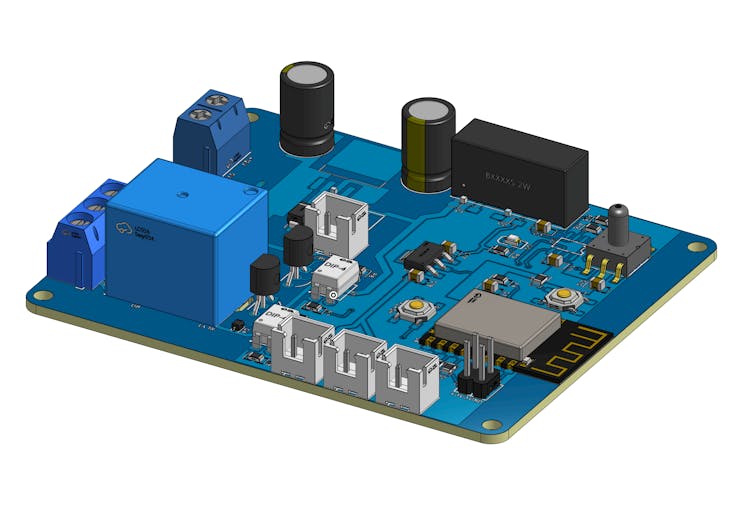
Final Result and Hardware in Action
After the entire design and technical validation process, the result is a compact, robust, and field-ready electronic board. The integration between the high-resolution reading of the HX710B and the processing of the ESP8266 allowed for extremely stable pressure control, with immediate response times both in the activation of the local relay and in updating data via the cloud.
Below, you can see the final PCB assembly, highlighting the organization of the power (GND A) and sensitive signal (GND B) sectors, ensuring the thermal efficiency and noise immunity discussed earlier.
Open Documentation and PCBWay Support
This project was only possible thanks to the support of PCBWay, one of the world leaders in the manufacture of high-quality printed circuit boards. They ensured that the complex layout, with power traces and galvanic isolation, was executed perfectly.
Want to build your own version of this board? I am making all the project documentation openly available! You can download the electronic schematic and production-ready Gerber files right now.
Furthermore, in partnership with PCBWay, you have the opportunity to bring your project to life: new users can get up to 10 free electronic boards by registering on the website. It's the perfect opportunity for you to start your IoT pressure monitoring tests without manufacturing costs!