 Tim
TimThis is a quick one. I noticed that the TL431 precision voltage reference was surprisingly cheap:

In fact, that is less than the cost of many transistors (to be fair, the price of "brand" devices is a bit higher). A typical use case is to provide a voltage reference of 2.5V. (From TIs datasheet)
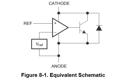
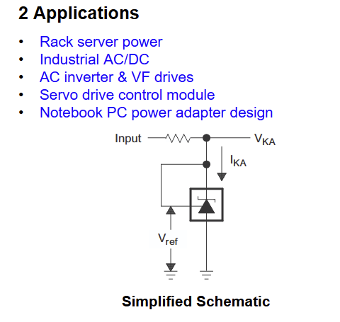
Another way to look at this, is an open-drain inverter with a threshold of 2.5V. Assume this circuit:

When the input is below 2.5V, no current will flow through the device and the 1kOhm resistor pulls the output to 5V. When the input is above 2.5V, current will flow from "cathode" to "anode", pulling the output down. The minimum appears to be around 2V since the output driver is a darlington NPN transistor. The bias current to the input is rather low (<50µA), which means that we can achieve a high fan-in and fan-out.
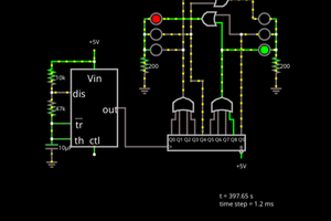
We can connect five of these inverters to form a ring oscillator. I used a model from here for simulation in LTSpice.

And it oscillates! We see, that the logic low level is 2V, logic high is 5V. The oscillator frequency is 96kHz. This indicates a propagation delay of ~1µs. Which is... ok.

- Connect the outputs of two TL431 inverters to the same pull up. (3xR + 2x TL431 per gate)
- Use a resistor devidier at the input. (3xR + 1x TL431 per gate)
Interestingly, option 2 (the simpler one), works with this logic family specifically due to the asymmetric logic levels. We can probably achieve up to NOR4 with this concept. (Consider what happens if 3 inputs are low and one high)

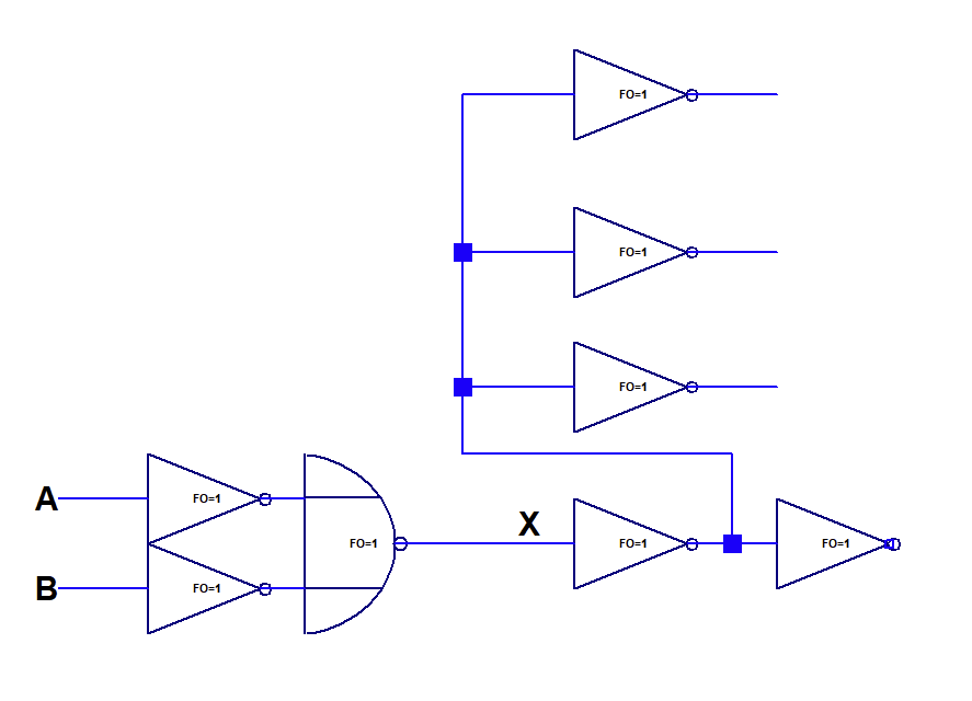
Above, you can see the schematics of the gate along with a test circuit.
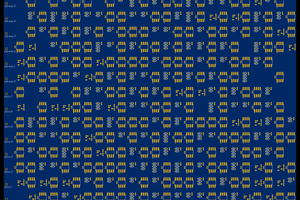
Results of the test circuit simulation is shown below. NOR2 works nicely, which means we can build up a full logic family from it. Also the second inverter with a loading with 4 inverters nicely retains logic levels.
 Great, another hacky dicrete logic family! It's nice, because it looks robust, easy to build and cheap. I'd say its somewhat preferrable to RTL. The biggest drawback is its low speed and the odd logic levels.
Will I build a processor out of it? Probably not, for now...


 Al Williams
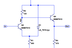
Consider trying minority vote of three logic. Usual difficulty might be a drifty threshold, but you have a stable reference and sufficient gain to drive a full scale result.