 Hernán Valdés
-
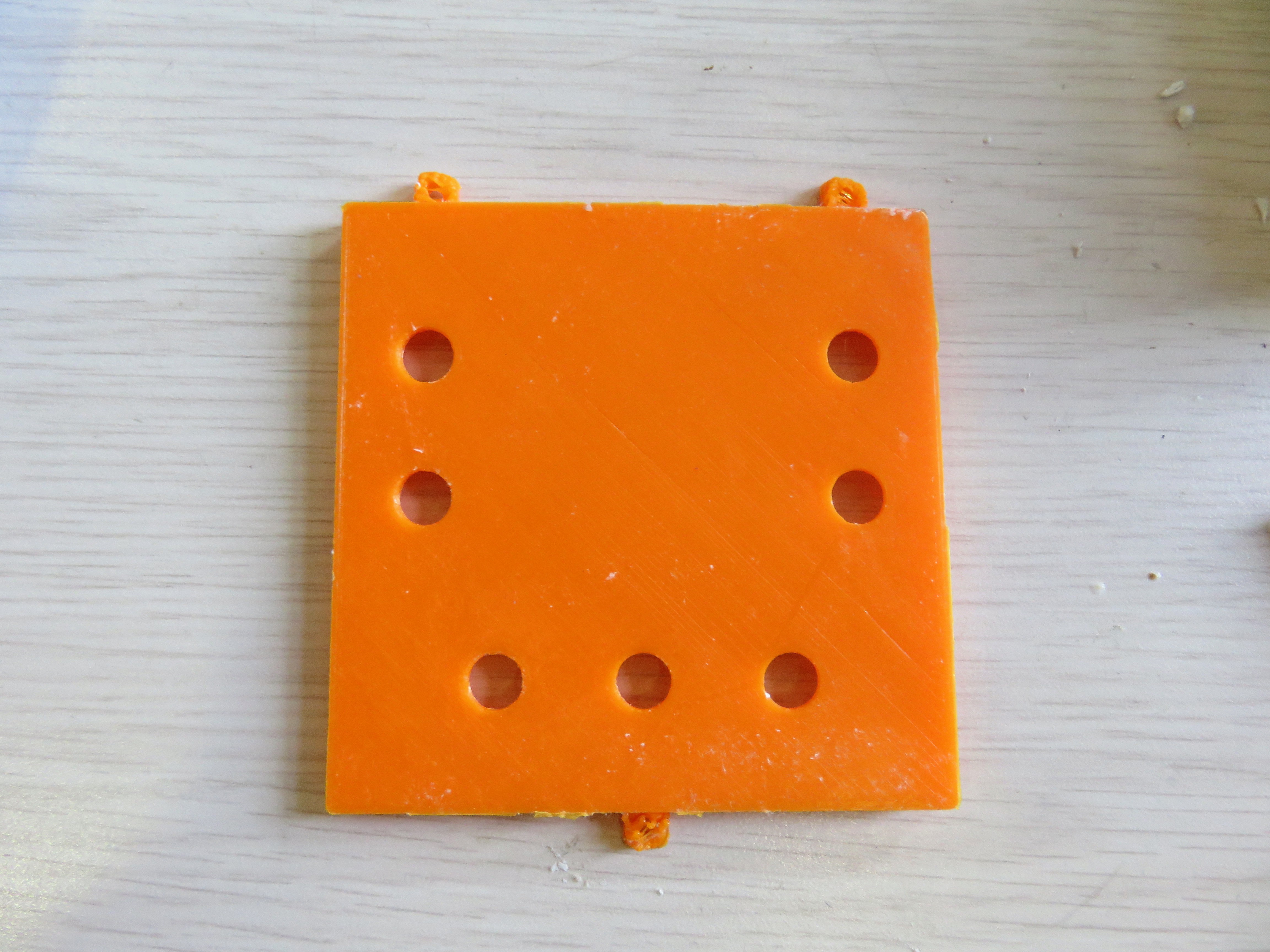
1Print the parts for the enclosure
![]() 1.stl
1.stl![]()
2.stl
-
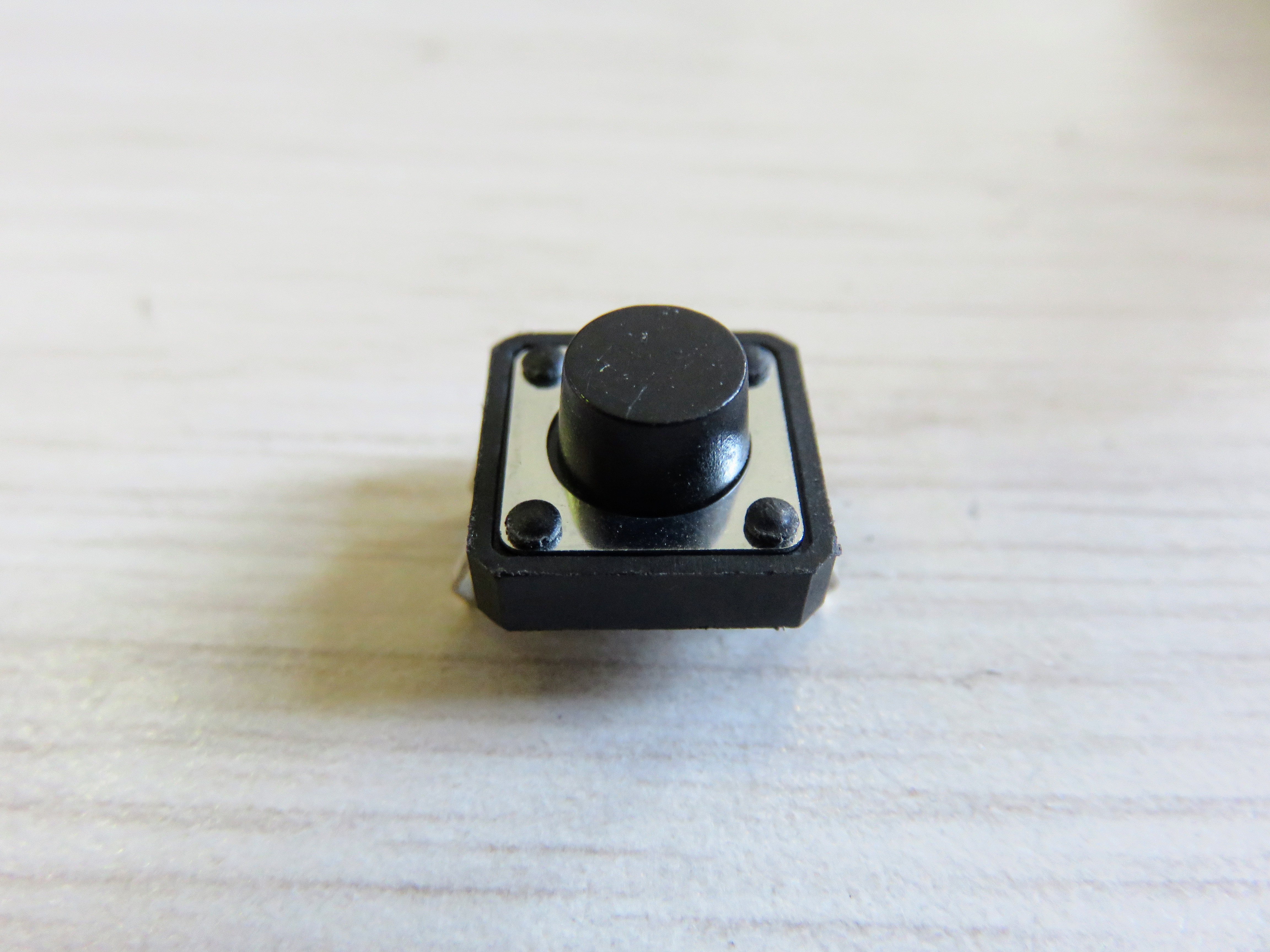
2Add the buttons (Super Glue requiered)
You can use a different glue, but for me Super Glue was very effective
![]() The dimensions of the microswitch are 12x12mm and 6mm height.
The dimensions of the microswitch are 12x12mm and 6mm height.![]()
-
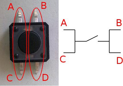
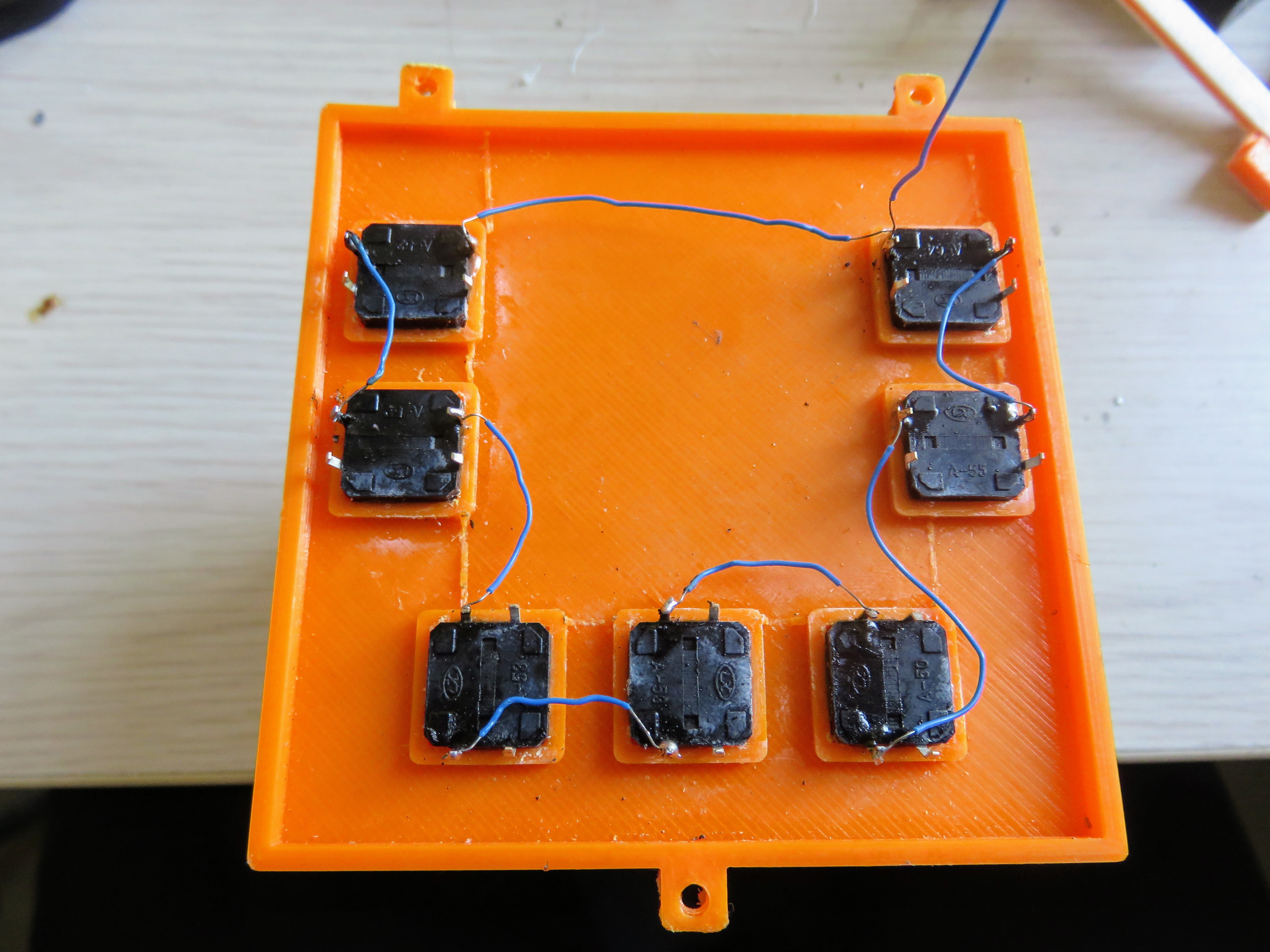
3Solder a common wire for the buttons
![]()
A and C, B and D are connected, so what we need to do is to connect every C with the A of the next button. After that we can give with only one cable 3.3v to the whole system.![]()
-
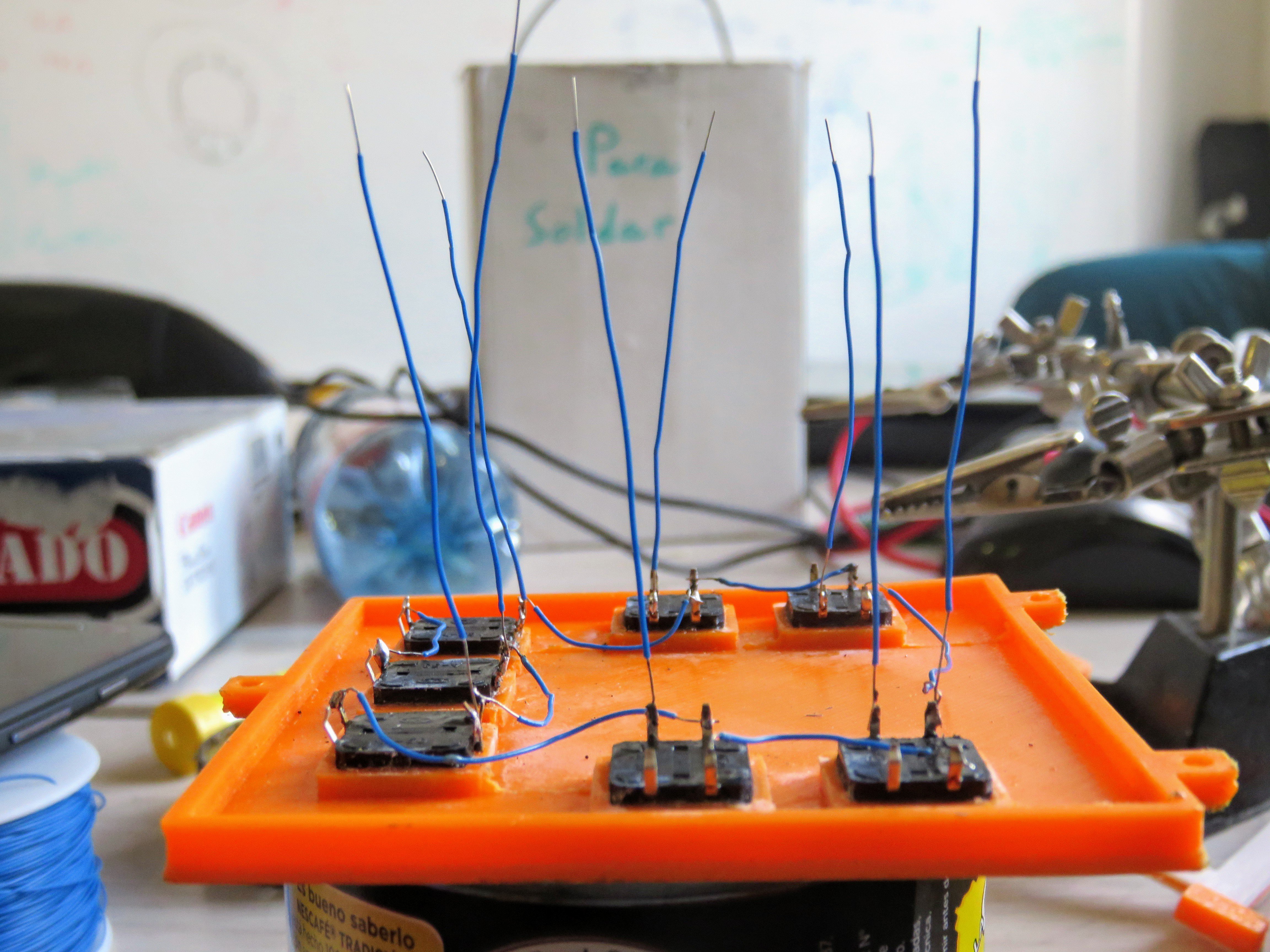
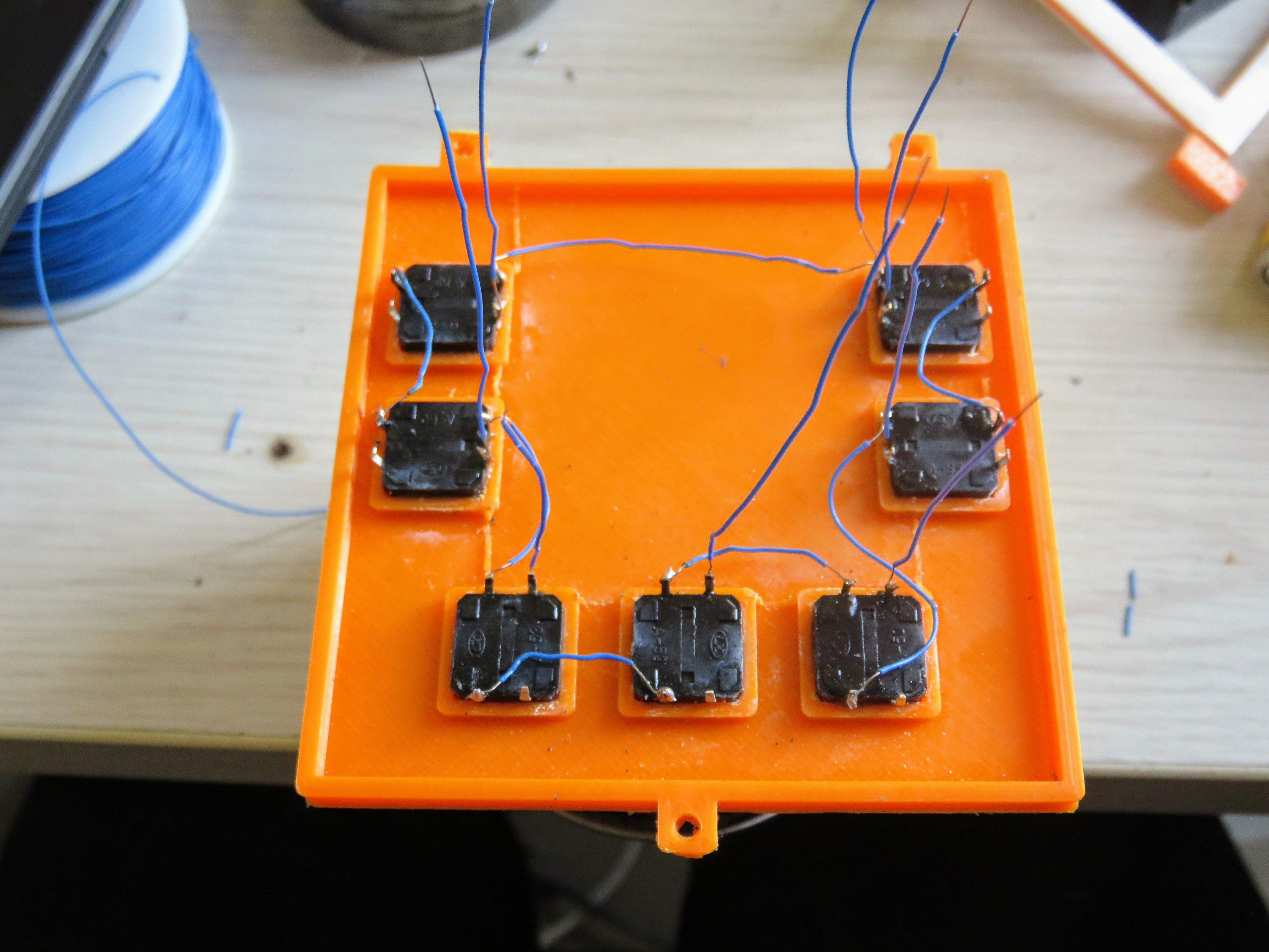
4Solder a ground wire for every button
Following the schema from the step 3, we need to solder a cable to every B pin in the whole button system.
![]()
![]()
-
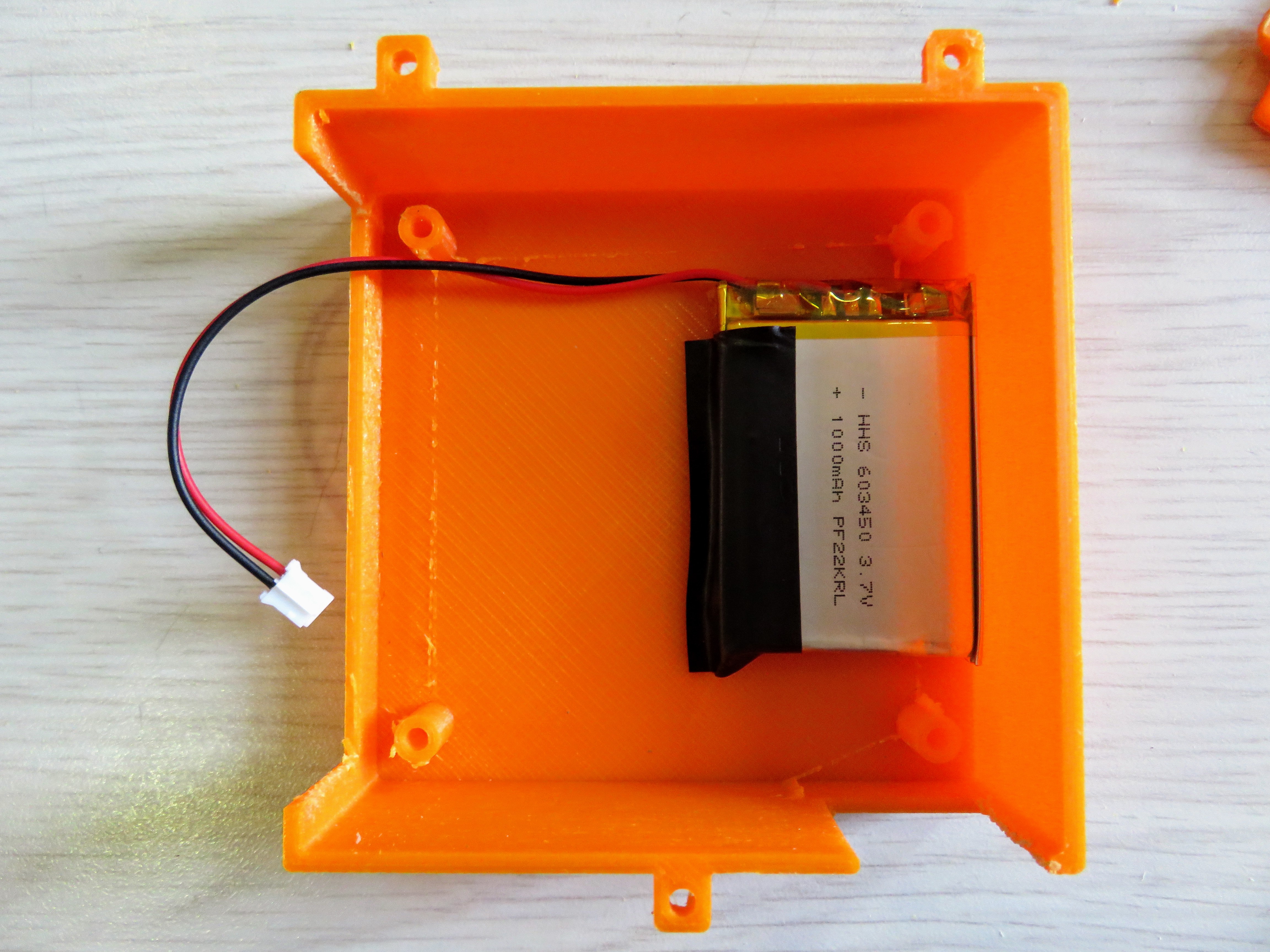
5Place the battery
I have used Double Sided Tape and some Electric Tape to place the battery.
![]()
-
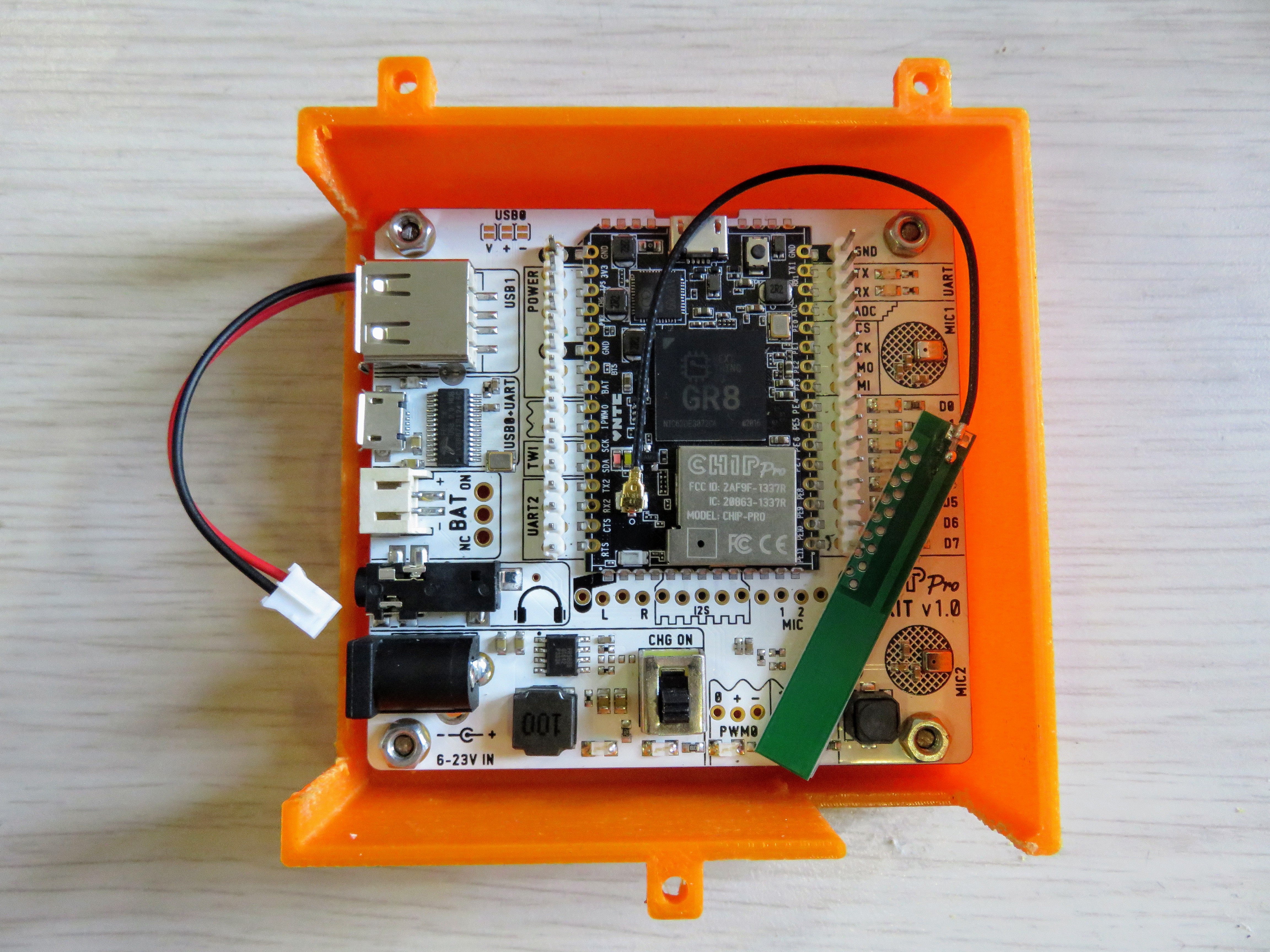
6Place the microprocessor (CHIP Pro Dev. Board)
![]()
-
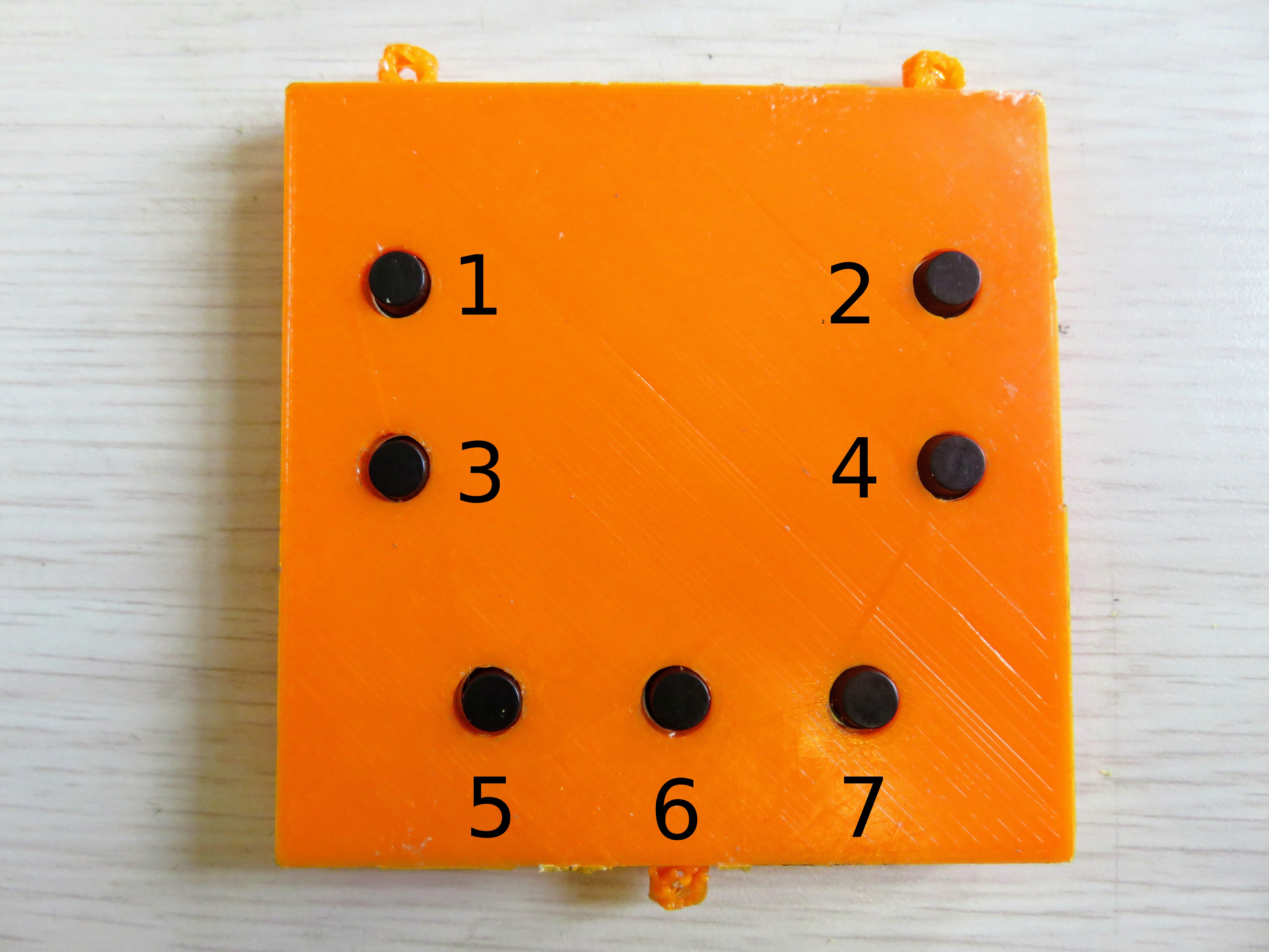
7Solder the buttons to CHIP Pro Dev. Board
Considering the following enumeration of the buttons :
![]()
- Solder the button 1 to D1, button 2 to D2 and following the sequences until the button 7 that is also D7.
- You need to solder the common wire to 3.3v.
-
8Flash CHIP Pro with a debian distro
Following the instructions available in the documentation of CHIP Pro flash the microprocessor with a Debian distro.
-
9Connect to CHIP Pro
Following the instructions available in the documentation of CHIP Pro connect via screen (for MAC or Linux in your PC) to the microprocessor.
-
10Connect to WiFi
Assuming that you are already connected through Screen with CHIP Pro, we are going to set a Wifi connection. You can follow the instructions from the CHIP Pro documentation.
Neltume: Language learning device for blind people
Language learning device for blind people
 1.stl
1.stl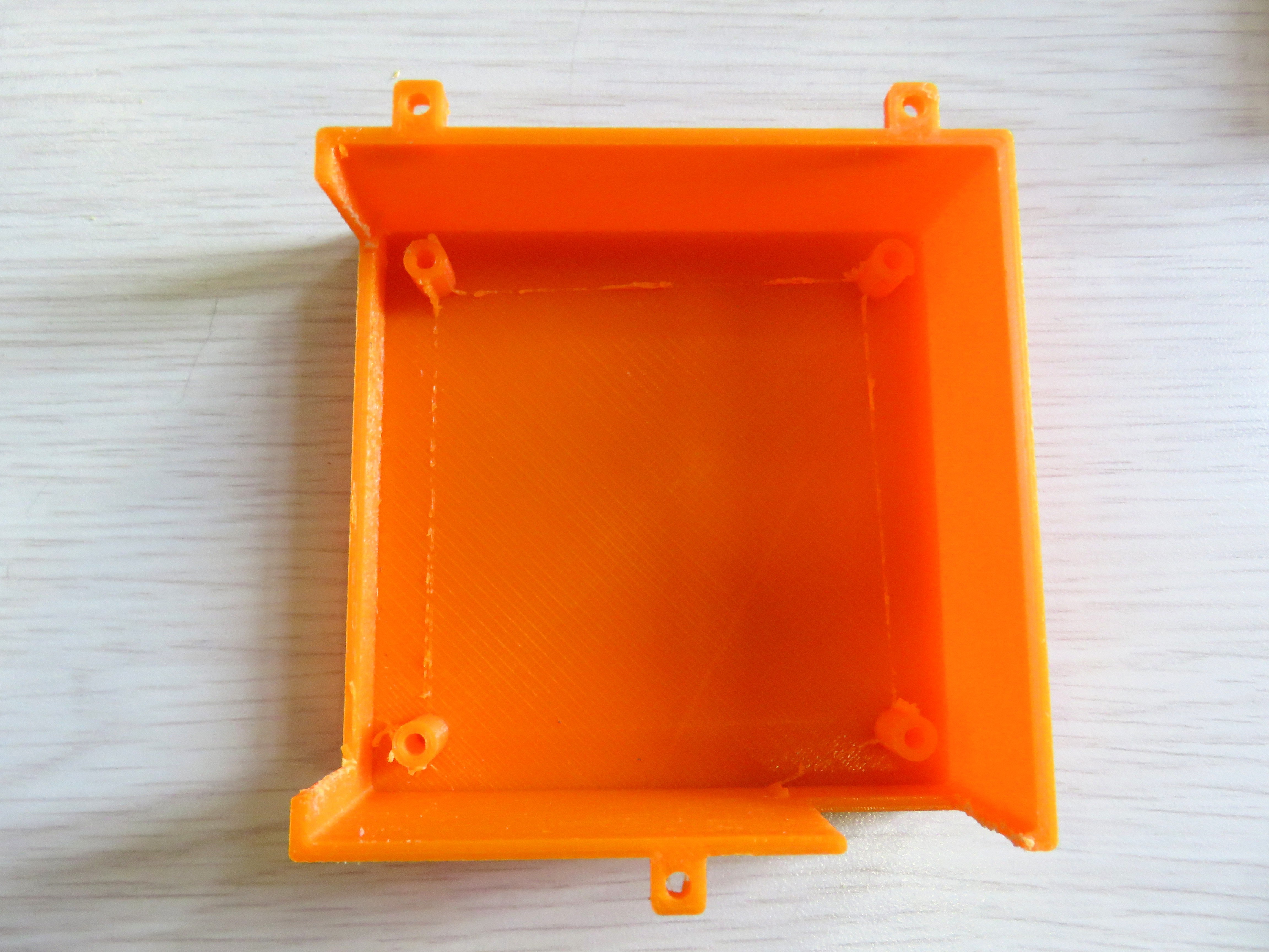
 The dimensions of the microswitch are 12x12mm and 6mm height.
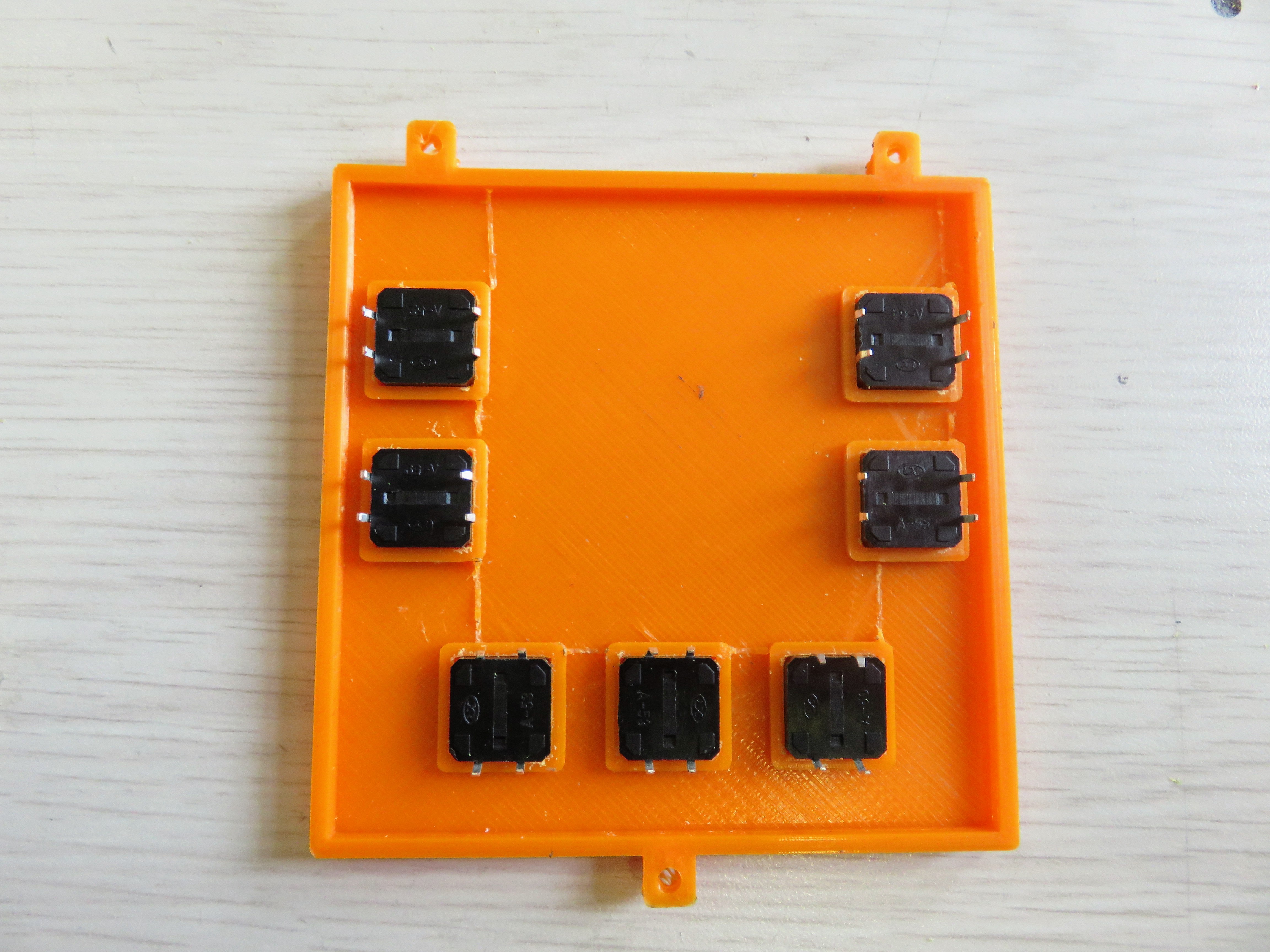
Discussions
Become a Hackaday.io Member
Create an account to leave a comment. Already have an account? Log In.