 Ai-Thinker
A fall detection algorithm can determine if an object has fallen by detecting changes in acceleration and angular velocity. When implementing the MPU6050 fall detection algorithm, the first step is to read the raw data from the MPU6050 sensor.
Then, calculate the rate of change of acceleration and angular velocity to judge if a fall has occurred. Typically, a threshold can be set to determine if acceleration and angular velocity exceed the normal range. If they exceed the threshold, the object is considered to have fallen. Additionally, machine learning algorithms can be used to improve the accuracy of fall detection.
By training on a large amount of data from fall and non-fall states, a model can be built to determine if a fall has occurred. This method better adapts to different objects and environments, enhancing the sensitivity and accuracy of fall detection.
Introduction to the Main Hardware Used in the Device
There are many introductions to the MPU6050 online from various bloggers.https://zhuanlan.zhihu.com/p/346764320
I. Introduction to the MPU6050
The MPU-60X0 is the world's first 9-axis motion processing sensor. It integrates a 3-axis MEMS gyroscope, a 3-axis MEMS accelerometer, and an extensible Digital Motion Processor (DMP).
It can connect to a third-party digital sensor, such as a magnetometer, via the I2C interface. After expansion, it can output a 9-axis signal through its I2C or SPI interface (the SPI interface is only available on the MPU-6000). The MPU-60X0 can also connect to non-inertial digital sensors, such as pressure sensors, via its I2C interface.
The MPU-60X0 uses three 16-bit ADCs (0~65535) for the gyroscope and accelerometer respectively, converting the measured analog quantities into output digital quantities.
To accurately track both fast and slow movements, the sensor's measurement ranges are user-configurable: the gyroscope can measure ±250, ±500, ±1000, ±2000°/s (dps), and the accelerometer can measure ±2, ±4, ±8, ±16g.
The chip measures 4×4×0.9mm, uses a QFN package (Quad Flat No-leads package), can withstand a maximum shock of 10,000g, and features a programmable low-pass filter.
The internal block diagram of the MPU6050 is shown below:
Among the pins to understand: SCL and SDA are the IIC interfaces connecting to the MCU, which controls the MPU6050 through this IIC interface. There is another IIC interface: AUX_CL and AUX_DA, which can be used to connect external slave devices such as a magnetometer, forming a 9-axis sensor.
VLOGIC is the IO port voltage; this pin can go as low as 1.8V, and we usually connect it directly to VDD. AD0 is the address control pin for the slave IIC interface (connected to the MCU), controlling the least significant bit of the IIC address. If connected to GND, the MPU6050's IIC address is 0X68; if connected to VDD, it is 0X69.
Note: The addresses 0x68 and 0x69 here do not include the least significant bit used for data transmission, so they are not 8-bit data. For example, 0x68 represents 110 1000, and 0x69 represents 110 1001. The least significant bit is typically used to indicate the IIC master's read/write mode. Self-test is for self-diagnosis, which tests the sensor's mechanical and electrical structure to check if the chip is damaged. After self-test is activated, the circuit activates the sensor and generates an output signal. Detailed descriptions of self-test can be found in the official chip manual, as follows:
- Gyroscope Self-Test When self-test is activated, the on-board electronics will actuate the appropriate sensor. This actuation will move the sensor’s proof masses over a distance equivalent to a pre-defined Coriolis force. This proof mass displacement results in a change in the sensor output, which is reflected in the output signal. The output signal is used to observe the self-test response. The self-test response is defined as follows: Self-test...
 tehaxor69
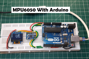
 Lithium ION
 ThunderSqueak
 Ken Yap