 ElectroScope Archive
Introduction
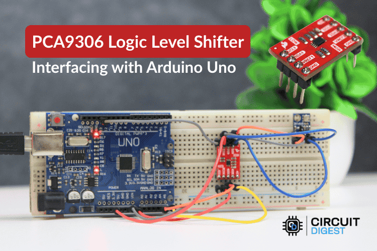
In many embedded projects, you’ll encounter devices running at different logic voltages — for example, a 5 V Arduino Uno talking to a 3.3 V I2C sensor. Directly wiring those together can damage hardware or lead to unreliable communication. That’s where the PCA9306 bidirectional I2C level shifter becomes invaluable: it reliably translates both clock and data lines between different voltage domains without altering your Arduino code.
This post walks through the PCA9306 hardware, wiring, example Arduino code, and real-world tips that you can copy, adapt, and improve in your own projects.
What Is the PCA9306 and Why Use It?
The PCA9306 is a purpose-built bidirectional voltage level translator for I2C and SMBus communication between devices that run at different logic voltages. Unlike simple resistor dividers or unidirectional TTL translators, the PCA9306:
-
Automatically detects and shifts both SDA and SCL directions based solely on logic transitions — no configuration in firmware.
-
Supports logic from ~1.2 V up to 5.5 V on either side — making it perfect for interfacing 5 V Arduinos with 3.3 V sensors and microcontrollers.
-
Preserves I2C protocol behavior such as clock stretching, arbitration, and standard/fast modes (up to 400 kHz).
What makes this chip remarkable is that it doesn’t require any software changes — the hardware takes care of bidirectional translation automatically.
PCA9306 Module Pinout & Function
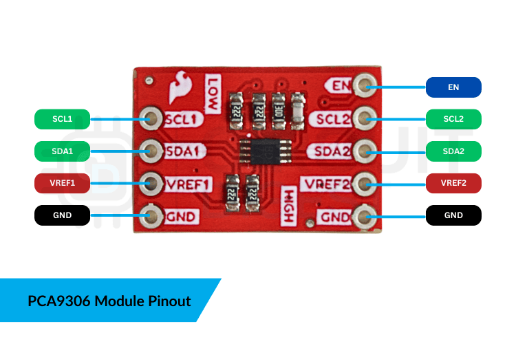
Here’s what each pin does:
-
VREF1 (Low Voltage Reference): Connects to your lower logic domain (e.g., 3.3 V)
-
VREF2 (High Voltage Reference): Connects to your higher logic domain (e.g., 5 V)
-
SCL1 / SDA1: I2C clock and data for the low-voltage side
-
SCL2 / SDA2: I2C clock and data for the high-voltage side
-
GND: Common ground between all devices
-
EN: Pull this high (to VREF2) to enable the translator
Tip: A common ground between both devices and the level shifter is essential; without it, voltage references float and the I2C bus can become unstable.
Step-by-Step Wiring Guide
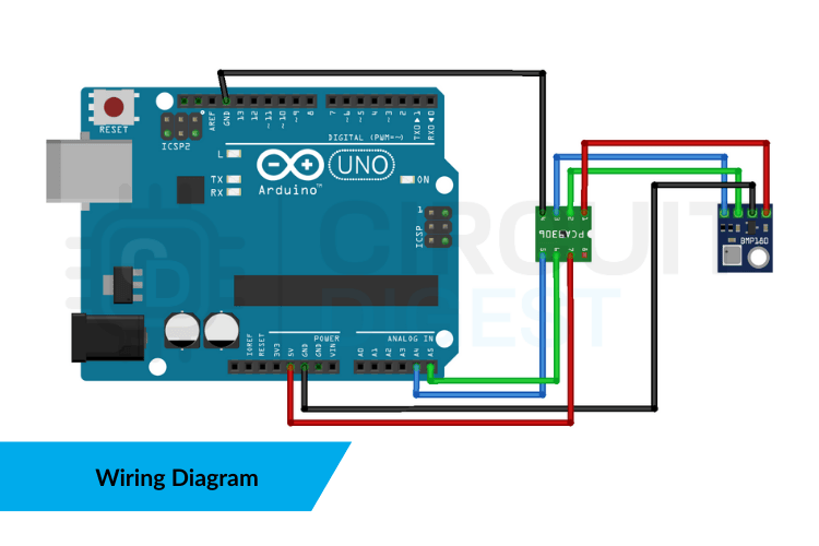
This example shows how to connect an Arduino Uno to a 3.3 V I2C sensor (like a BMP180 or similar), using the PCA9306 board as a level translator:
-
Power the Level Shifter
-
VREF1 → 3.3 V (sensor logic)
-
VREF2 → 5 V (Arduino logic)
-
-
Connect I2C Lines
-
SDA1/SCL1 → Sensor SDA/SCL
-
SDA2 → Arduino A4 (SDA)
-
SCL2 → Arduino A5 (SCL)
-
-
Tie Grounds Together
-
GND from Arduino, sensor, and PCA9306 must share a common reference.
-
-
Enable the Module
-
Pull the EN pin high (usually tied to the voltage on VREF2).
-
With this setup in place, the PCA9306 handles level shifting automatically — no software configuration is required.
Example Arduino Code
Once your hardware is connected correctly, your Arduino sketch doesn’t need any special libraries or PCA9306-specific code. It simply performs I2C operations exactly as you would with a direct connection:
#include <Wire.h>
#include <Adafruit_BMP085.h>

Adafruit_BMP085 bmp;

void setup() {  Serial.begin(9600);  Wire.begin();  // start I2C  if (!bmp.begin()) {    Serial.println("Sensor not found. Check wiring!");    while (1);  }
}

void loop() {  Serial.print("Temp (°C): ");  Serial.println(bmp.readTemperature());
  Serial.print("Pressure (Pa): ");  Serial.println(bmp.readPressure());    delay(2000);
}
This sketch demonstrates retrieving temperature/pressure values from a BMP180 sensor through a PCA9306 level shifter, then printing those values to the Serial Monitor.
Troubleshooting Tips
Even with correct wiring, I2C communication can fail due to:
-
Missing or weak pull-up resistors on either voltage domain
-
EN pin not held high
-
Excessively long wiring adding bus capacitance
-
Wiring SDA/SCL to the wrong pins on Arduino (use A4/A5)
You can also use a logic analyzer to verify that SDA and SCL signals are clean and correctly translated.
Real-World Uses & Benefits
The PCA9306 isn’t just for Arduino beginners — it’s a tool that brings...
Read more »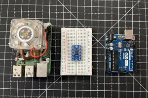
 Lithium ION
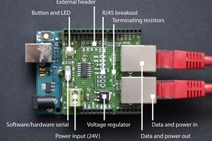
 Gregor
 Jens Geisler
 Piotr Gaczkowski