 Aleksandr
Video instruction:
The goal of this project is to take this poorly documented AliExpress driver and turn it into a DIY-ready component for a multi-axis robot.
1. Hardware Preparation & Mods
Before the driver is usable in a tight robot chassis, a few physical modifications are necessary:
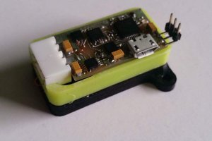
- Slimming the Profile: The stock screw terminals are far too bulky for a compact robot leg. I desoldered these and soldered motor wires directly to the PCB. For the power input, I switched to XT60 connectors, effectively cutting the board's total thickness in half.
- Thermal Management: While the driver is rated for 3kW, the stock plate isn't enough for sustained high-torque tasks. I designed custom 3D-printed mounts and adapted standard aluminum heatsinks to fit the MOSFET thermal pads for better heat dissipation.
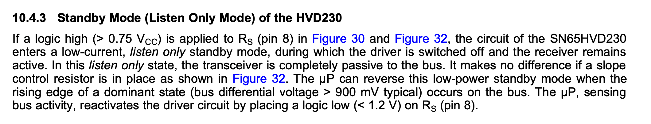
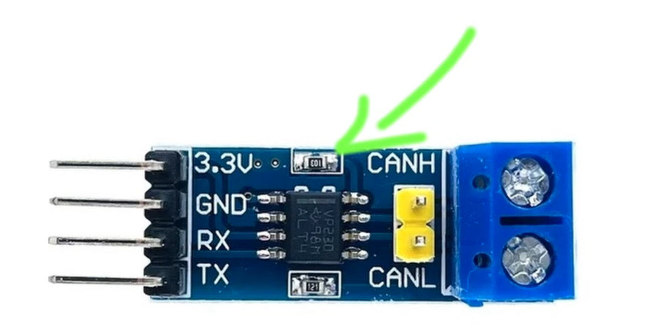
- CAN Transceiver Fix: The popular SN65HVD230 CAN module used with these boards has a design flaw: the RS pin resistor value is too high, forcing the chip into "Listen Only" or standby mode. I desoldered this resistor and shorted the pads to 0 ohms, ensuring the transceiver stays active for two-way communication.
2. Software Configuration
The MKS X Drive Mini (also called MKS Odrive Mini on some aliexpress shops) runs legacy ODrive v3.6 firmware (v0.5.1), and currently, the software is the biggest barrier to entry. The original ODrive documentation is outdated since they go closed-source, and the official desktop GUI is broken - it crashes on startup due to deprecated Python dependencies. While the command-line odrivetool is powerful, it is far too intimidating for most beginners.
- The GitHub "Cheat Sheet": To fix this, I created a universal configuration file available on my GitHub. Instead of digging through hundreds of settings, you only need to update the motor pole pairs parameter.
- Line-by-Line Setup: You can simply copy and paste the config from my repository into odrivetool line by line. This takes the guesswork out of the process and gets the motor spinning in minutes.
- The "Ghost Node" Fix: Included in the config is the command to move the phantom "Axis 1" to CAN ID 63. This prevents the default ID 1 conflict that usually crashes multi-driver systems.
3. ESP32 / Arduino Integration
To control a complex 16-axis system, a centralized controller is required to sync all movements.
- Communication: I used the ESP32-S3 hardware for its native CAN (TWAI) support.
- Custom Bridge: Since the standard ODrive Arduino library doesn't support the ESP32's CAN implementation out of the box, I created a custom adapter bridge. You can find the code on my GitHub.
- Performance: I am running the bus at a 500k baud rate. While it isn't CAN-FD, it provides enough bandwidth for multi-motor synchronization. I still need to investigate how the latency of standard CAN will affect sim-to-real precision for high-speed gaits.
4. Torque & Thermal Testing
I pushed these drivers using a high-torque test rig to find the actual limits of the $35 hardware.
- Results: Using an LA8308 170KV motor, I achieved roughly 2 Nm of torque at 50A and 1.2 Nm at 25A.
- Observations: The motor actually overheats much faster than the driver's MOSFETs. This proves the MKS has more power headroom than most hobby-grade motors can handle. The next step is to find even bigger, cheap motors to really see when this driver blows up!
 Karol
Karol
 Jithin Sanal
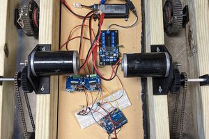
 David
David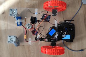
 Radu Pascal