 Capt. Flatus O'Flaherty ☠
-
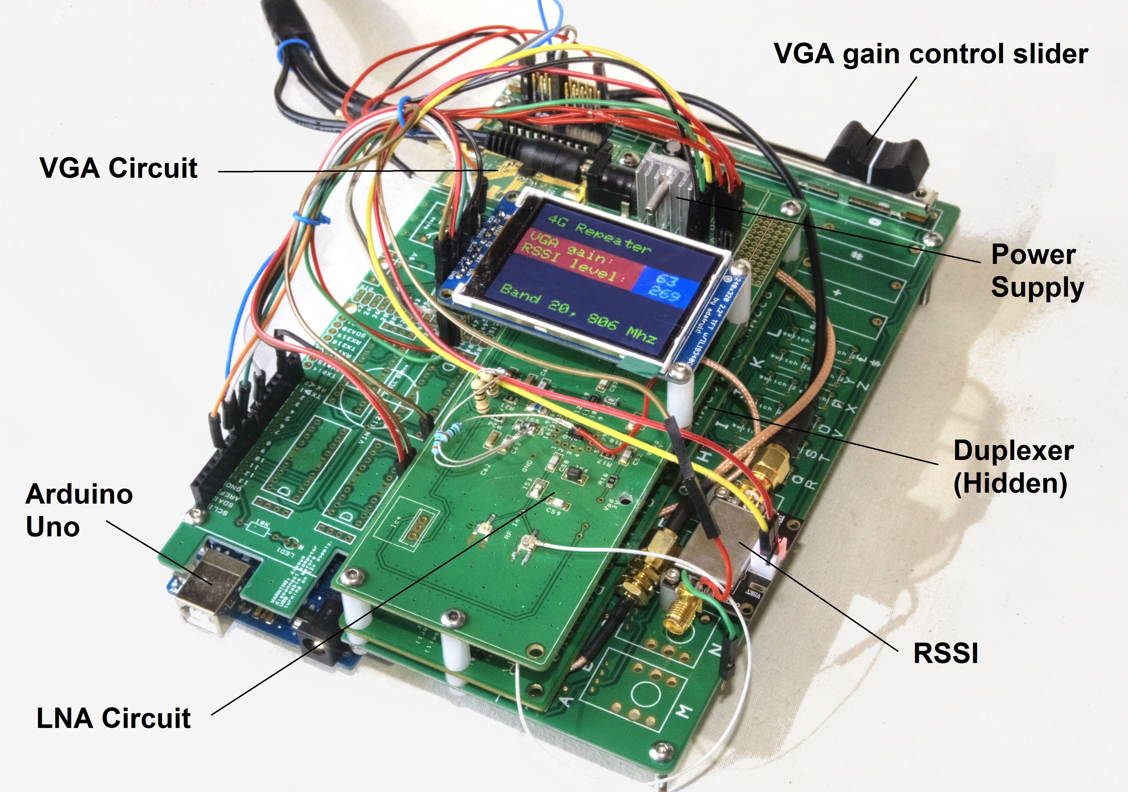
Testing the Product
07/22/2017 at 16:57 • 0 commentsAfter assembling the new 4 layer PCB with my manual pick and place machine I soldered on all the larger parts by hand and plugged it in ....... No response! Ah well, I thought the odds of it working were about 75% so it was no great surprise :( But since it works at relatively low voltage, it's always worth touching some of the connections with a finger as this is a really quick way of either totally destroying the components or galvanising them into action. I am one of the fortunate creatures on this planet who are blessed with electric fingers !
Anyway, the 'Electric Finger' test worked and suddenly the device started working ! It seems I had left out an important power connection to the VGA, which was fixed by soldering on an extra wire.
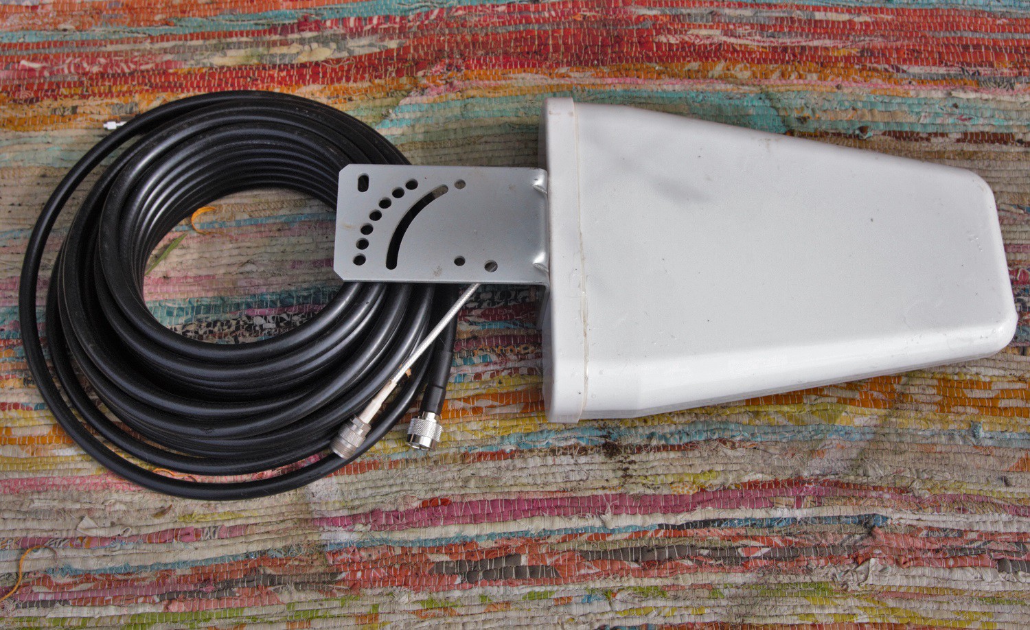
The other useful thing that I did was to upgrade the outside antenna and cable:
![]() This antenna was installed about 20' up in the air, with the pointy end directed towards my local 4G base station, which is about 8 miles away. The cable is very 'high performance', with 3dB loss over 15 metres and the antenna itself has a gain of about 6dB so that's a net gain of 3dB.
This antenna was installed about 20' up in the air, with the pointy end directed towards my local 4G base station, which is about 8 miles away. The cable is very 'high performance', with 3dB loss over 15 metres and the antenna itself has a gain of about 6dB so that's a net gain of 3dB.During testing, the VGA was behaving a bit strangely, so I used one of the 'intersection' antenna sockets to effectively avoid using it, and to my surprise, the 2 stage LNA chip provided plenty of power on it's own when receiving the signal from the base station. Note that I am making no attempt to transmit to the base station at this time as it's not needed where I live - my phone's transmit capability is fine on it's own. Transmitting to the base station has to be done very carefully as getting it wrong can cause very serious problems, so I'm going to attempt this much later in the project.
The test showed a 15dBm increase in signal strength with just the first stage of the LNA in operation and a massive 40dBm with both stages working, which gave a useful range of about 10m inside a building. It was very useful to be able to control the device like this as quite often, for convenience, the phone is positioned quite close to the inside antenna and in this case just using the primary stage of the LNA was highly beneficial.
The video below shows the device being controlled with 2 push button switches via an Arduino Uno:
-
Transformation Day
07/21/2017 at 12:32 • 6 comments![]() We now have a product - a basic 4G cell phone signal booster that works on band 20 (800 MHz). As far as a business plan is concerned, this could be sold as a kit where the user does all the easy, labour intensive soldering and simply buys the main PCB ready populated with the fiddly SMT components. It can also be hacked to work as a general purpose microwave RF digitally controlled amplifier for experimentation, but be warned - this gadget is capable of quite high transmission power - up to 1/2 watt - and a special operation license may be required. As a cell phone booster it works at a power in the order of 1 mW with a maximum range of about 10 metres so does not risk interfering with the neighbours too much.
We now have a product - a basic 4G cell phone signal booster that works on band 20 (800 MHz). As far as a business plan is concerned, this could be sold as a kit where the user does all the easy, labour intensive soldering and simply buys the main PCB ready populated with the fiddly SMT components. It can also be hacked to work as a general purpose microwave RF digitally controlled amplifier for experimentation, but be warned - this gadget is capable of quite high transmission power - up to 1/2 watt - and a special operation license may be required. As a cell phone booster it works at a power in the order of 1 mW with a maximum range of about 10 metres so does not risk interfering with the neighbours too much.![]()
Here, above, the massive conglomeration of wires and circuit boards of the prototype on the left is miraculously shrunk into one neat unit with only two loose wires which will connect to the indoors and outside antennae. Fear not, the device is still fairly hackable and even supports addition of the nice pretty Adafruit TFT screen with special mounting holes and connections, if required (but not essential).
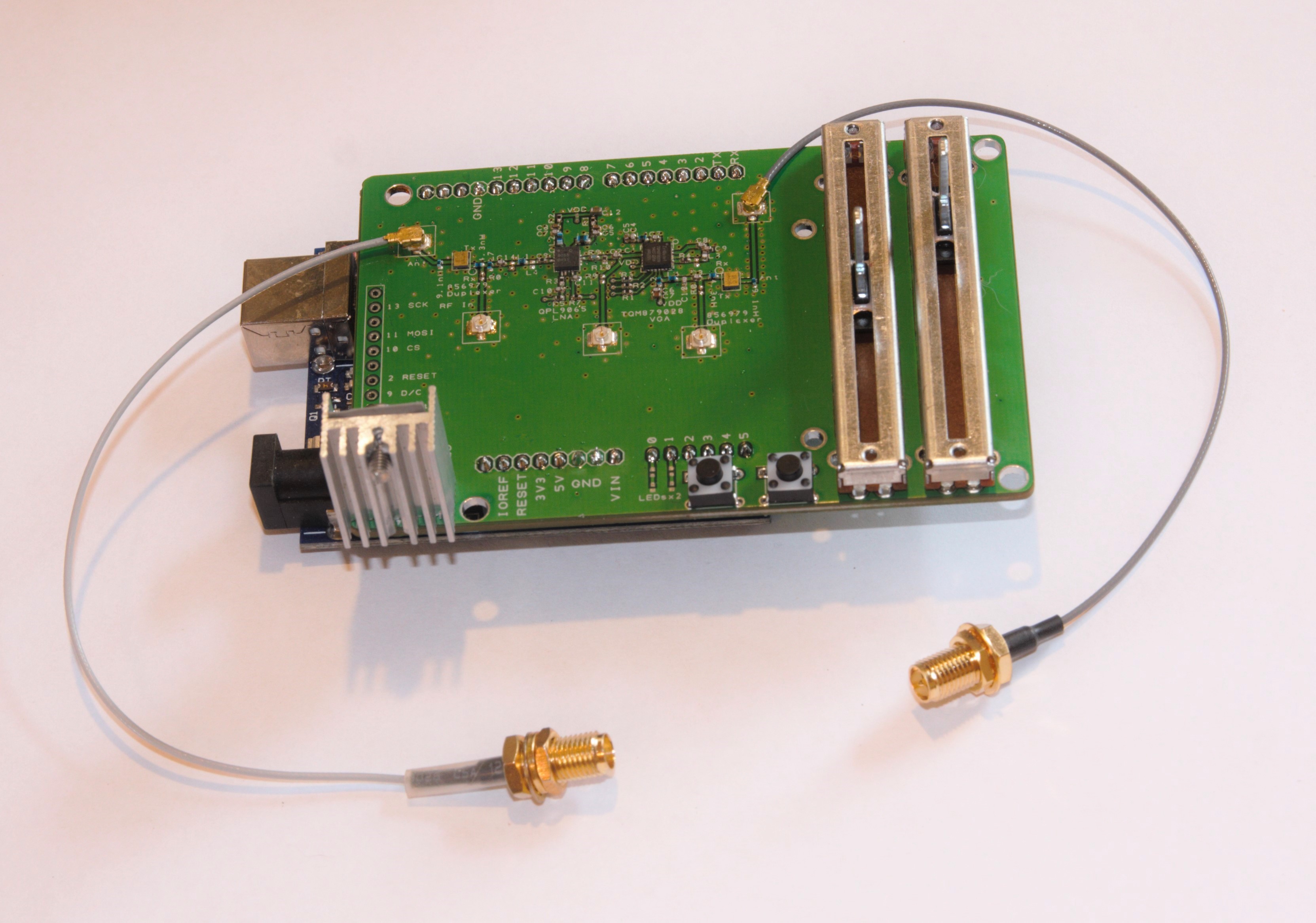
Finished, fully assembled, Arduino Cell Phone 4G Signal Booster as below. I did a quick test today and it actually worked! Still some room for improvement though.
![]() Schematic is HERE.
Schematic is HERE.PCB design file is HERE.
BOM is HERE.
-
Cell Phone Behaviour - Town v. Country
07/10/2017 at 15:49 • 0 commentsToday I decided to go on a religious pilgrimage to my local cell phone base station.
After making the necessary offerings and sacrificing of a few chickens I turned on my RSSI test rig and began uploading live video to YouTube:
![]() Basically, I made about 1,000 measurements from an RSSI (Received Signal Strength Indicator), one every second, that I bought from ebay, based on the Analogue Devices AD8318. Datasheet HERE.
Basically, I made about 1,000 measurements from an RSSI (Received Signal Strength Indicator), one every second, that I bought from ebay, based on the Analogue Devices AD8318. Datasheet HERE.The hypothesis was that my cell phone would transmit at lower power when close to the base station.
With the antenna at the same 200mm from the phone, I drove out into the countryside and found a spot with really bad 4G coverage -120 Dbm compared to -71 Dbm in the town. I then repeated the RSSI test, storing all the data on a micro USB in the Arduino rig. And here's the result:
![]() There's a really obvious difference in behaviour between town and country. In the country my phone is transmitting at markedly higher power. I'm not sure if the graph is logarithmic or not - I'd have to look that up on the RSSI chip's datasheet.
There's a really obvious difference in behaviour between town and country. In the country my phone is transmitting at markedly higher power. I'm not sure if the graph is logarithmic or not - I'd have to look that up on the RSSI chip's datasheet.Looking at the green countryside graph, there's two obvious 'plateaux' right at the bottom where the phone is doing nothing. We don't get that on the orange town graph because there's loads of other phones nearby transmitting on the same 4G band.
Why is this important? ........ Because it shows that either the base station can control the signal strength given out by each individual phone in it's catchment range by using a control signal ..... Or that the phone itself responds to low received signal strength by increasing it's transmit strength, guessing that it is a long way from the base station. In either case, the base station is probably going to get really annoyed if we boost our cell phone signal too much - no amount of sacrificed chickens is going to appease it's wrath! It's therefore really important to have individual gain controls on both the Rx and Tx in the cell phone booster.
-
Control LimeSDR Tx Gains using Arduino Due and Analogue Slider
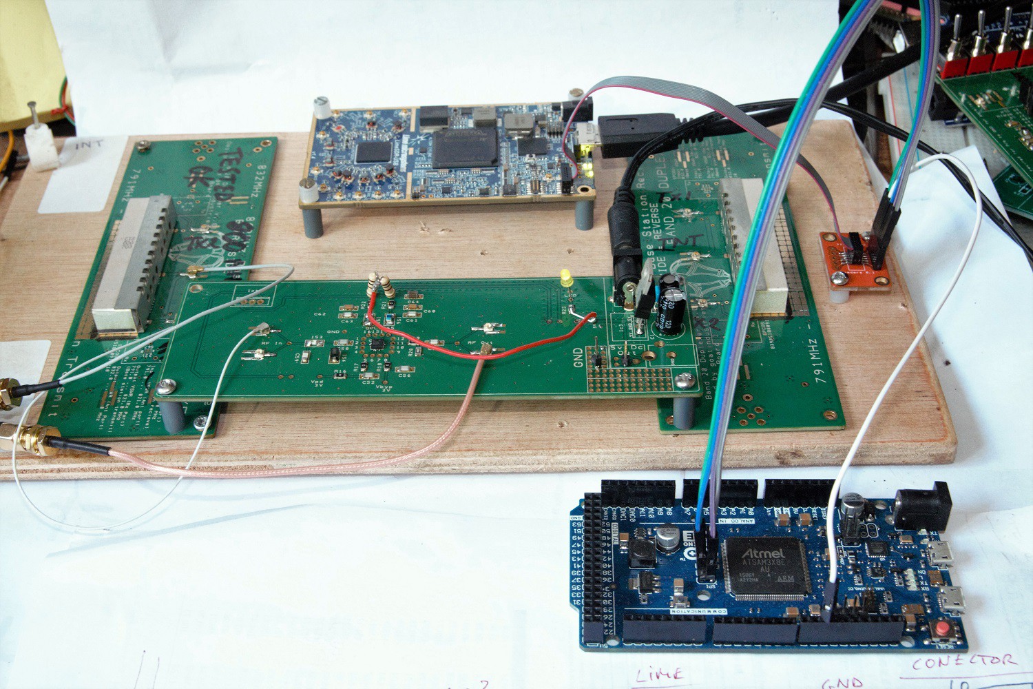
07/03/2017 at 17:08 • 1 commentPlease remember that this project has split into two - I'm exploring 2 possible solutions to the same problem, one using discrete components ie ICs and passives and the other a fully blown transceiver with built in FPGA - the LimeSDR.
So here I'm looking at option 2 - Using the LimeSDR.
The advantage of the Lime is that all the discrete components are located in one chip, the LimeLMS7002M, with an amazing array of registers that can be controlled using the SPI bus. As an example, register address 0x0100 can be set to a value of 0x7A94 to give a gains of 15 dB on the Tx pad. There's also a massive FPGA chip that has enough spare silicon inside to house a fairly powerful onboard Arduino (Work in progress) and even some basic signal processing.
Here, the limeSDR is programmed with a special FPGA configuration file: FILE and, when 'normal' operation is required, is programmed back with this, somewhat out of date, file: FILE. The Arduino Due is programmed with this file: FILE.
The main obstacle to success with this small step forward was getting the Arduino to replicate what I had previously achieved with the Limesuite software about a month ago. In theory, I should just be able to harvest all the register settings from Limesuite and copy and paste them into the Arduino program but ...... for a long while ...... No success. Eventually I narrowed it down to the fact that there is one particularly clever register that switches all subsequent register read/writes from one channel to the other ..... Confusing? Actually, the Lime LMS7002M datasheet explains it quite clearly and since I had already read the datasheet 5 times, it was no great surprise!
LMS7002M_WR(0x0020, 0xFFFD); //This register sets the following registers back to Read and Write Channel A only:Other than that there is a register to describe the DC correction, which is pretty essential:
LMS7002M_WR(0x0204, 0xF020); // DC Correction.This code reads the slider value and spits out hex integers that the LMS7002M will recognise:
   int sliderValue = analogRead(A0);
   sliderValue = sliderValue/0x21;
   int gainValue = 0x7800 + sliderValue * 0x42;
And here is the nice simple SPI write:
// Write register value to LMS7002M via SPI
void LMS7002M_WR(int addr, int val)
{
  digitalWrite(LMS7_SS_Pin, LOW);
  SPI.transfer( ((addr >> 8) | 0x80) );
  SPI.transfer( (addr & 0xFF) );
  SPI.transfer( ((val >> 8) & 0xFF) );
  SPI.transfer( (val & 0xFF) );
  digitalWrite(LMS7_SS_Pin, HIGH);
}
Oh, there's also a spreadsheet HERE for converting the Limesuite register list to an Arduino 'register function list'. It does character analysis/manipulation to change everything in column 'A' to column 'F':
![]() Having a gain control slider on a 4G signal booster is pretty essential as the base station signal can vary in strength quite a bit depending on local weather conditions and, of course, we don't want too much gain or else we could get feedback between the local Rx and Tx antennae. Looking at some of the 'Black Box. signal boosters in the market place, I can't understand why they don't have a simple manual gain control so that systems can be tweaked to individual antennae setups. Actually, I think that some of them do 'appear' to have gain control, but actually it is fake!
Having a gain control slider on a 4G signal booster is pretty essential as the base station signal can vary in strength quite a bit depending on local weather conditions and, of course, we don't want too much gain or else we could get feedback between the local Rx and Tx antennae. Looking at some of the 'Black Box. signal boosters in the market place, I can't understand why they don't have a simple manual gain control so that systems can be tweaked to individual antennae setups. Actually, I think that some of them do 'appear' to have gain control, but actually it is fake!Anyway, If the isolation between antennae can be made really high by, for example, separating them by 100m, then the gain could be turned up and greater coverage could be obtained. But ..... 100m ..... That's a lot of cable and probably a substantial antenna installation.
Especially for Ebrahim Bushehri, here's video of the Arduino Due controlling the LimeSDR Tx gain:
-
Analogue Repeater now assembled
06/16/2017 at 12:24 • 0 comments![]()
![]()
![]()
We now have a functional repeater with manual variable gain control and screen for displaying stuff. I think a nifty graph dislaying RSSI against time would be cool?
-
Testing Qorvo TQM879028 Variable gain amplifier
06/12/2017 at 19:46 • 0 commentsAfter trying to use the Analog devices HMC742A VGA for a third time with no success, I went back to the search filters and specifically selected Qorvo as my preferred manufacturer, mostly because their technical support is truly fantastic.
I'd seen their variable gain development board before, but was put off by the fact that it was tuned to 2150 MHz which is quite a bit above the 806 MHz that I required. I'm now pretty sure I can replace the necessary passives to correct it. Whether it was the fact that their dev board was very reasonably priced or just plain desperation, I do not know, but I'm very glad I bought it as I got it working fairly quickly. It even comes with a USB adapter daughter board and windows evaluation software - Total bargain!
The really great thing about this gadget is that it has some real power - a massive 0.5 watts! It needed to be cascaded with my QPL9065 low noise amp, but that was ok. The results were very nice indeed. Now to get it hooked up to an Arduino via SPI and insert a RSSI unit to monitor the signal strength.
-
LimeSDR now controlled by Arduino via SPI
06/10/2017 at 17:15 • 0 comments![]() At last I've managed to connect the LimeSDR to an Arduino Due. I was delayed by trying to mess about with JTAG adapters and only solved the problem by making a custom PCB to breakout the 0.05 inch pitch JTAG connector:
At last I've managed to connect the LimeSDR to an Arduino Due. I was delayed by trying to mess about with JTAG adapters and only solved the problem by making a custom PCB to breakout the 0.05 inch pitch JTAG connector:![]()
The SPI connection has been tested and is working nicely. Now for some brain frazzling hex to binary register manipulation to load my repeater settings via the Arduino and then control it by the Arduino. Standalone repeater coming soooooooon!
-
RSSI test
06/10/2017 at 14:13 • 0 comments![]() The RSSI was inserted after the LNA circuit and the antenna was moved in and out of a Faraday cage. The voltage recorded varied between 1.6 and 1.3 volts. I would have expected it to be about 2.1 volts inside the cage after looking at the datasheet for the RSSI.
The RSSI was inserted after the LNA circuit and the antenna was moved in and out of a Faraday cage. The voltage recorded varied between 1.6 and 1.3 volts. I would have expected it to be about 2.1 volts inside the cage after looking at the datasheet for the RSSI. -
Long term test of analogue circuits
06/08/2017 at 17:16 • 0 comments![]() Since I actually need a 4G signal repeater in my office, I decided to run a more long term test of one of my analogue boards - a Low noise amplifier, the QPL9065.
Since I actually need a 4G signal repeater in my office, I decided to run a more long term test of one of my analogue boards - a Low noise amplifier, the QPL9065.With my plate antenna positioned 1/2m away from my phone I was able to get a consistent 20 dBm increase in signal strength and a reliable 4G data connection. I felt so confident that it was going to work that I used it to run/assist an important conference call with some of the guys from BT, Facebook and Lime Microsystems. There's nothing quite like working under pressure!
In the background of the photo above can be seen the LimeSDR with it's incredibly powerful LMS7002M chip. This chip contains all the necessary blocks that I need to complete this project but there are a few barriers that prevent me from using it namely:
- There's no breakout board for this chip alone unless I backstep to it's predecessor, the LMS6000.
- It requires a 6 layer PCB.
- KiCAD PCB design files are not available yet.
- Many functions are routed through the FPGA which prevents me from using them directly.
- Learning to use the FPGA is another steep learning curve.
-
LimeSDR now working as 4G signal booster
05/26/2017 at 15:17 • 0 commentsWhilst waiting for my analogue boards to arrive I thought I should spend a bit of time fiddling about with the calibration settings whilst running my Limesuite program in an attempt to get a clean Rx to Tx signal ....... And, surprise, surprise .... It started to work!
Cell Phone 4G LTE Repeater / Booster / Femtocell
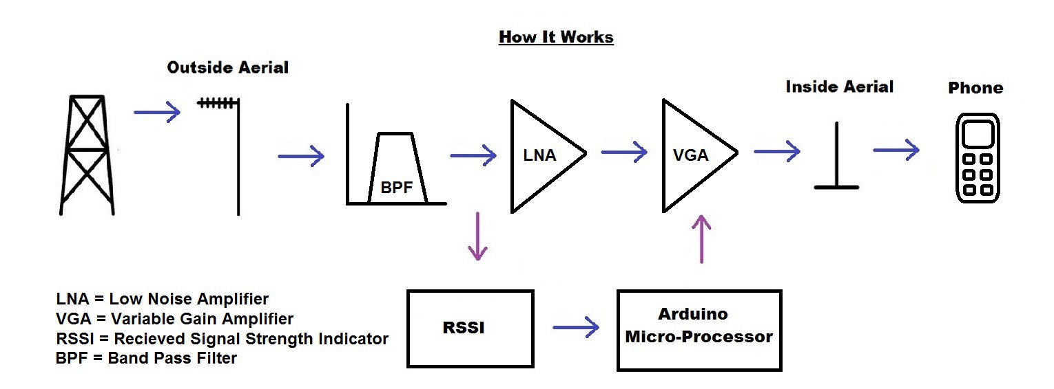
An outside pole mounted aerial picks up 4G signals which are then filtered, amplified and re-transmitted through a second inside aerial.
 This antenna was installed about 20' up in the air, with the pointy end directed towards my local 4G base station, which is about 8 miles away. The cable is very 'high performance', with 3dB loss over 15 metres and the antenna itself has a gain of about 6dB so that's a net gain of 3dB.
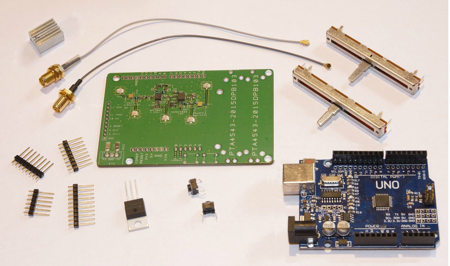 We now have a product - a basic 4G cell phone signal booster that works on band 20 (800 MHz). As far as a business plan is concerned, this could be sold as a kit where the user does all the easy, labour intensive soldering and simply buys the main PCB ready populated with the fiddly SMT components. It can also be hacked to work as a general purpose microwave RF digitally controlled amplifier for experimentation, but be warned - this gadget is capable of quite high transmission power - up to 1/2 watt - and a special operation license may be required. As a cell phone booster it works at a power in the order of 1 mW with a maximum range of about 10 metres so does not risk interfering with the neighbours too much.
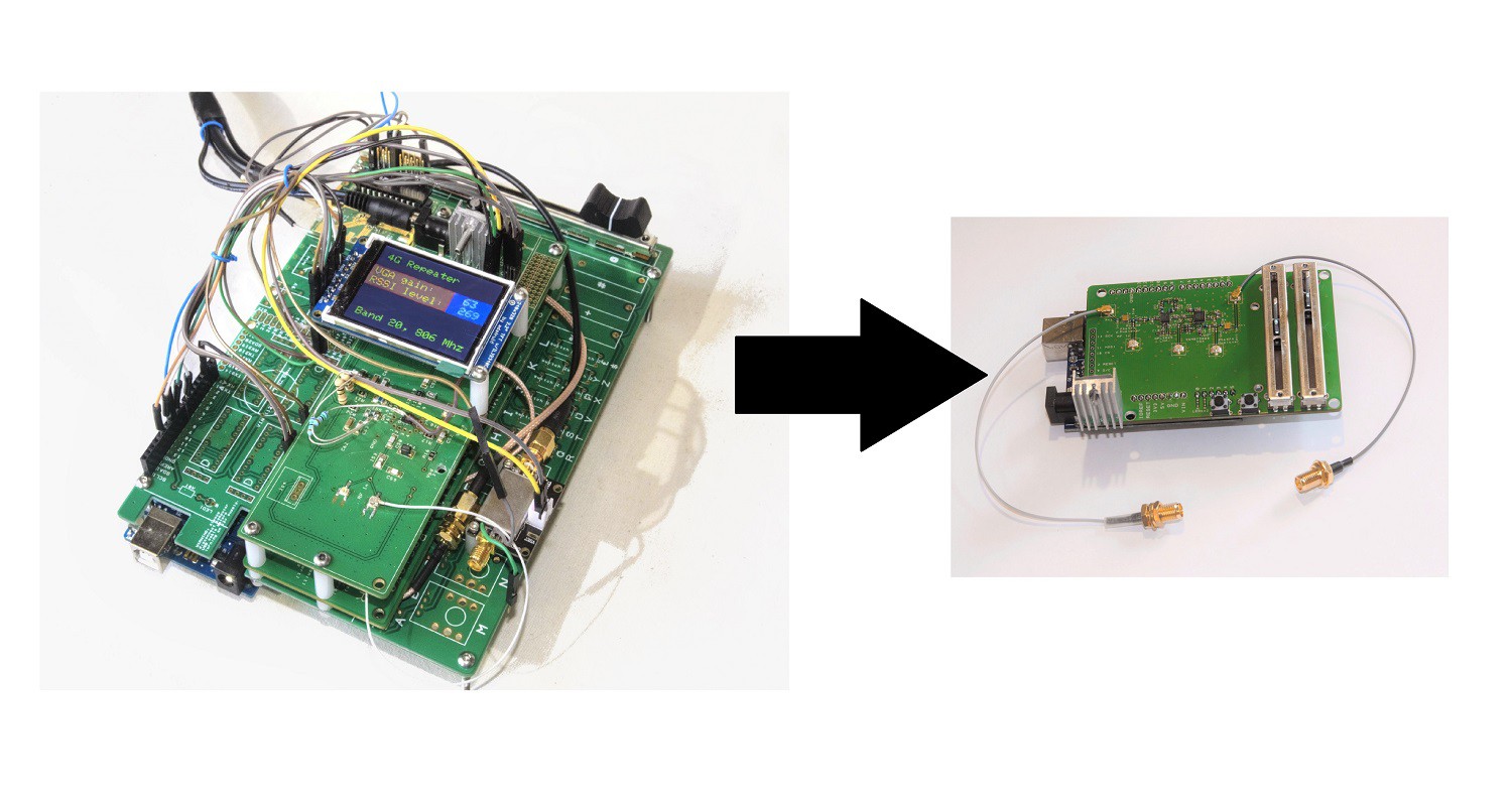
 Schematic is
 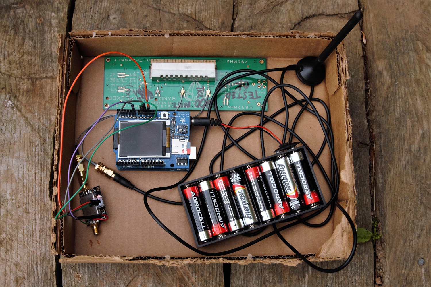 Basically, I made about 1,000 measurements from an RSSI (Received Signal Strength Indicator), one every second, that I bought from ebay, based on the Analogue Devices AD8318. Datasheet
 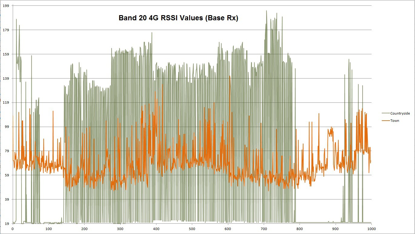 There's a really obvious difference in behaviour between town and country. In the country my phone is transmitting at markedly higher power. I'm not sure if the graph is logarithmic or not - I'd have to look that up on the RSSI chip's datasheet.
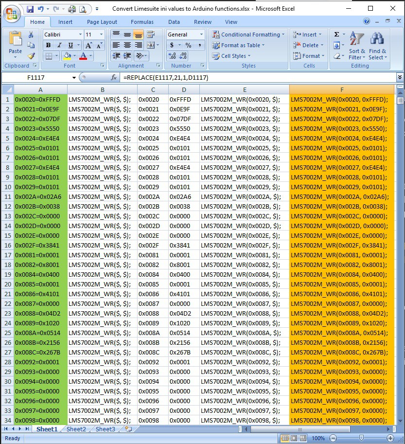 Having a gain control slider on a 4G signal booster is pretty essential as the base station signal can vary in strength quite a bit depending on local weather conditions and, of course, we don't want too much gain or else we could get feedback between the local Rx and Tx antennae. Looking at some of the 'Black Box. signal boosters in the market place, I can't understand why they don't have a simple manual gain control so that systems can be tweaked to individual antennae setups. Actually, I think that some of them do 'appear' to have gain control, but actually it is fake!
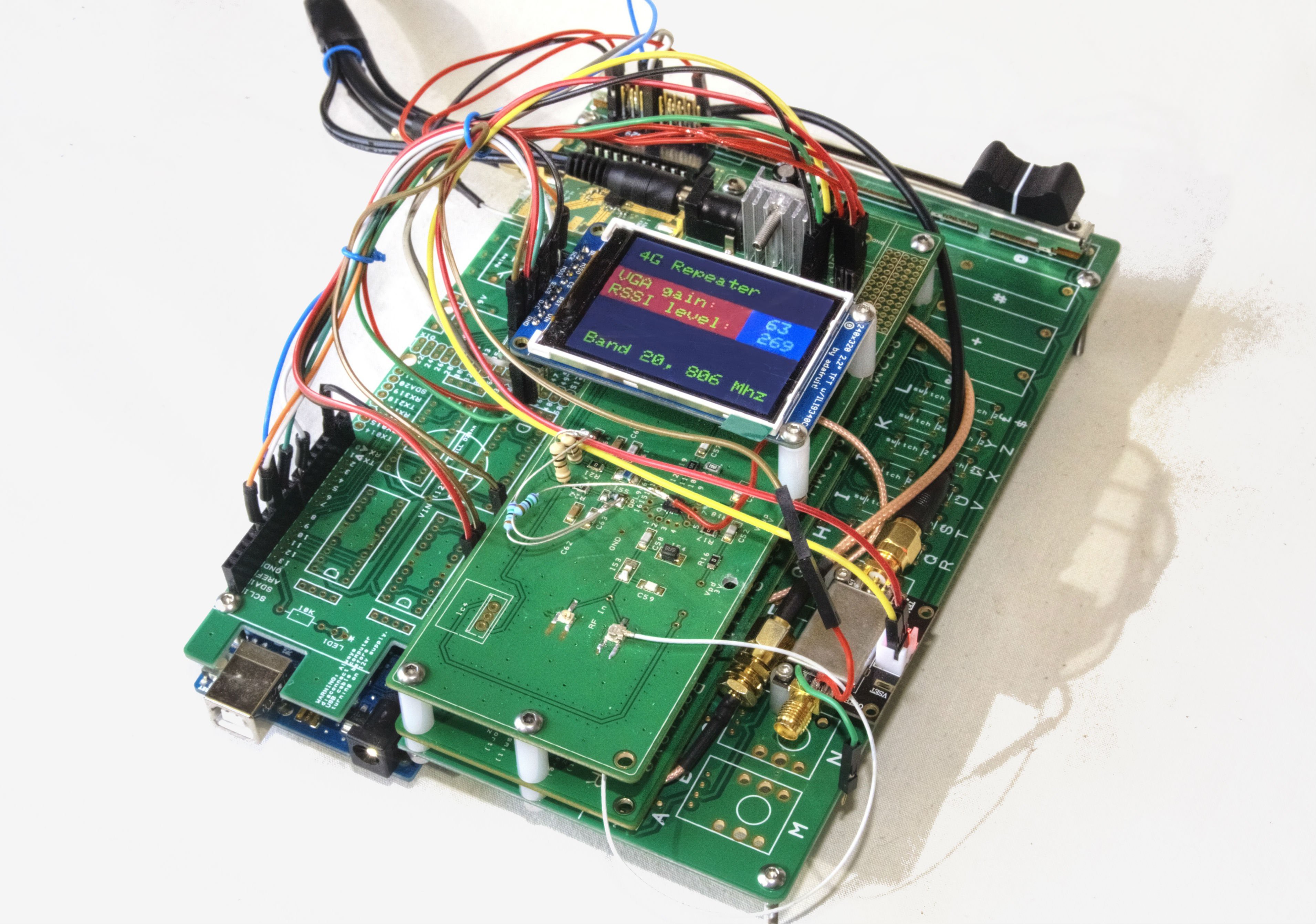
 At last I've managed to connect the LimeSDR to an Arduino Due. I was delayed by trying to mess about with JTAG adapters and only solved the problem by making a custom PCB to breakout the 0.05 inch pitch JTAG connector:
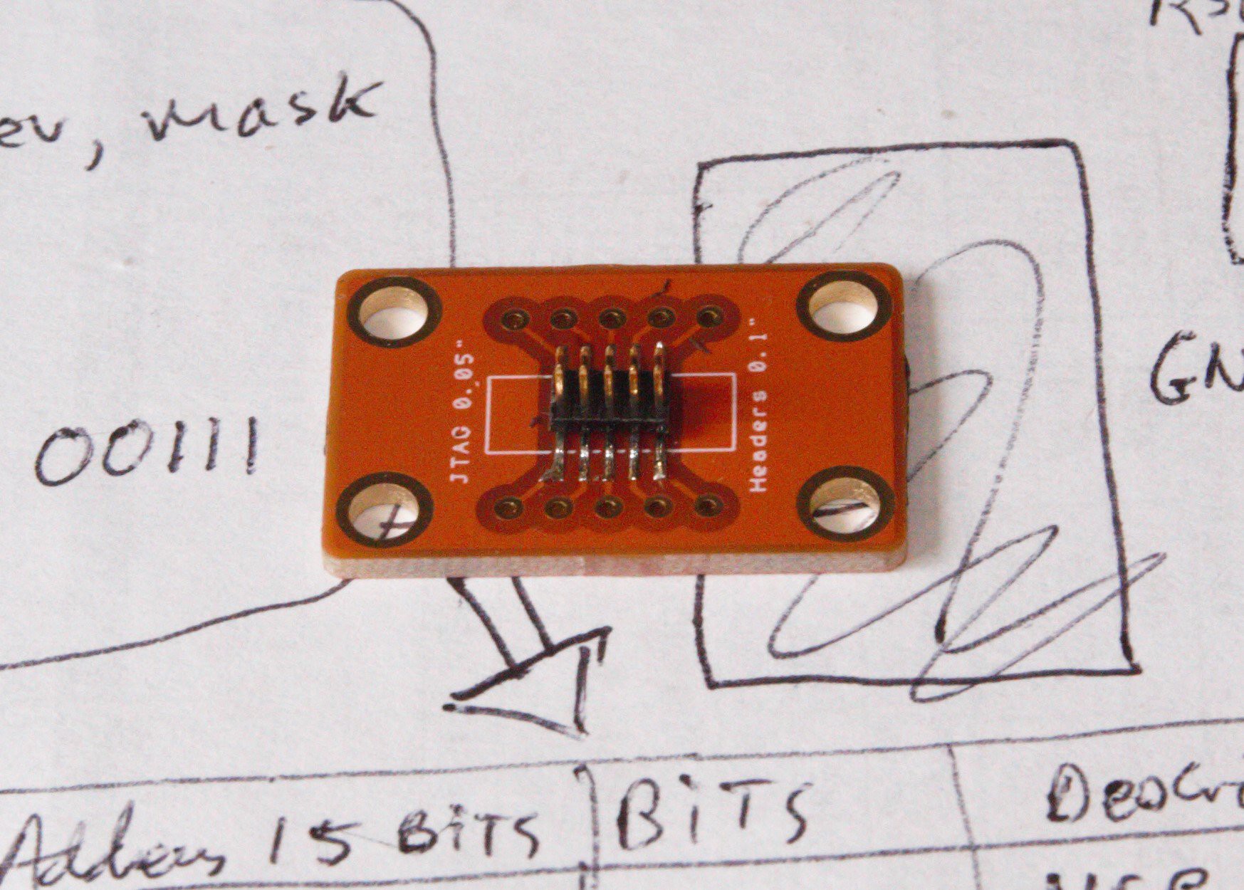
 The RSSI was inserted after the LNA circuit and the antenna was moved in and out of a Faraday cage. The voltage recorded varied between 1.6 and 1.3 volts. I would have expected it to be about 2.1 volts inside the cage after looking at the datasheet for the RSSI.
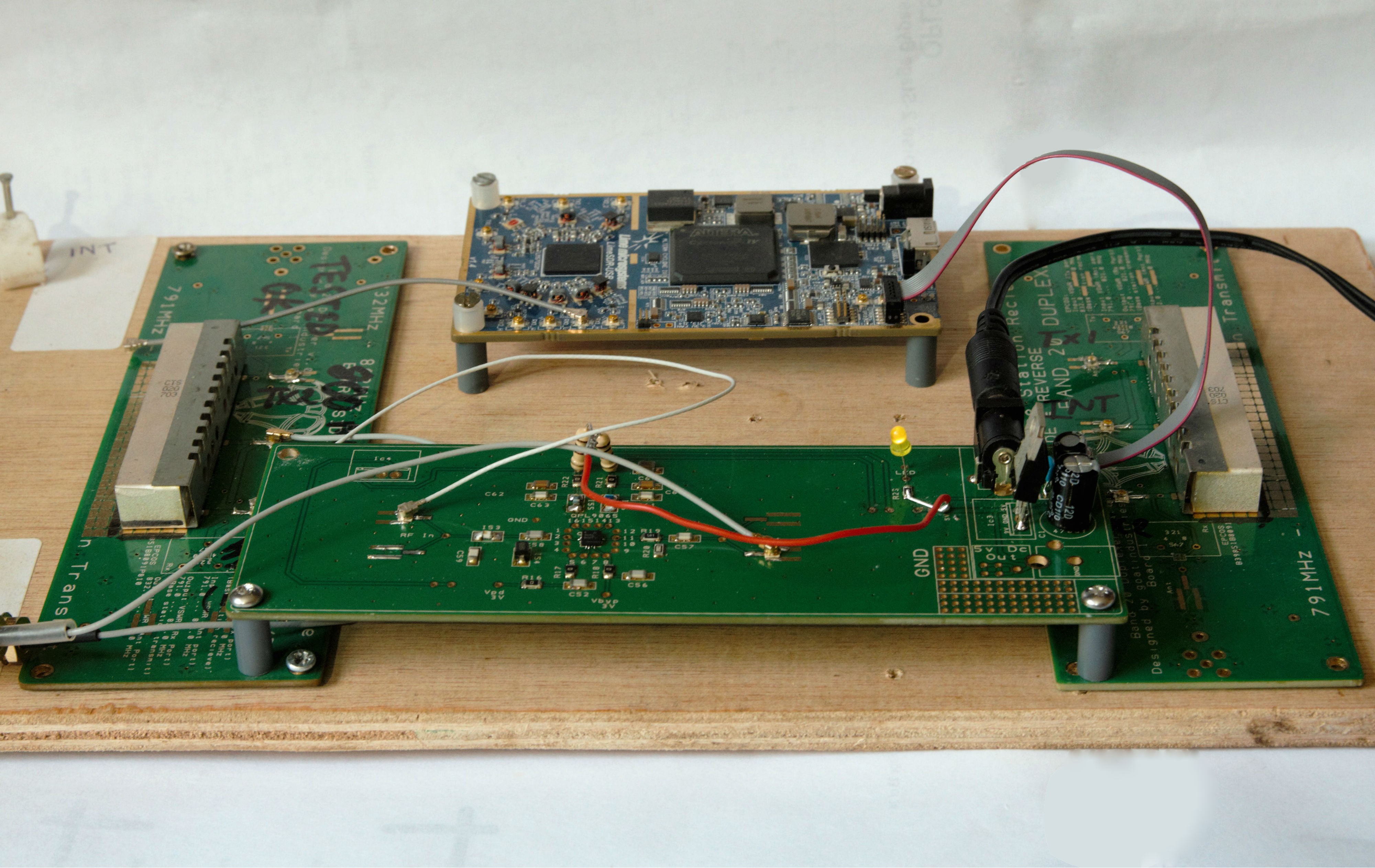 Since I actually need a 4G signal repeater in my office, I decided to run a more long term test of one of my analogue boards - a Low noise amplifier, the QPL9065.