 Capt. Flatus O'Flaherty ☠
-
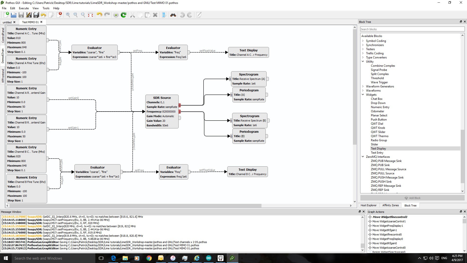
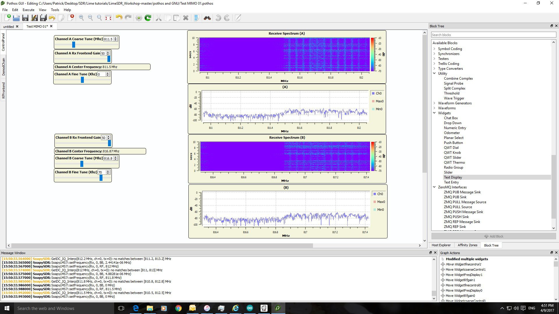
Testing MIMO capabilies of LimeSDR
04/09/2017 at 15:31 • 0 commentsNot sure what's going on here. Adjusting one channel seems to affect the other channel and I wouldn't expect that to happen! If anybody can check this out, the file is in the files section: Testing MIMO 01.pothos.
![]()
![]()
-
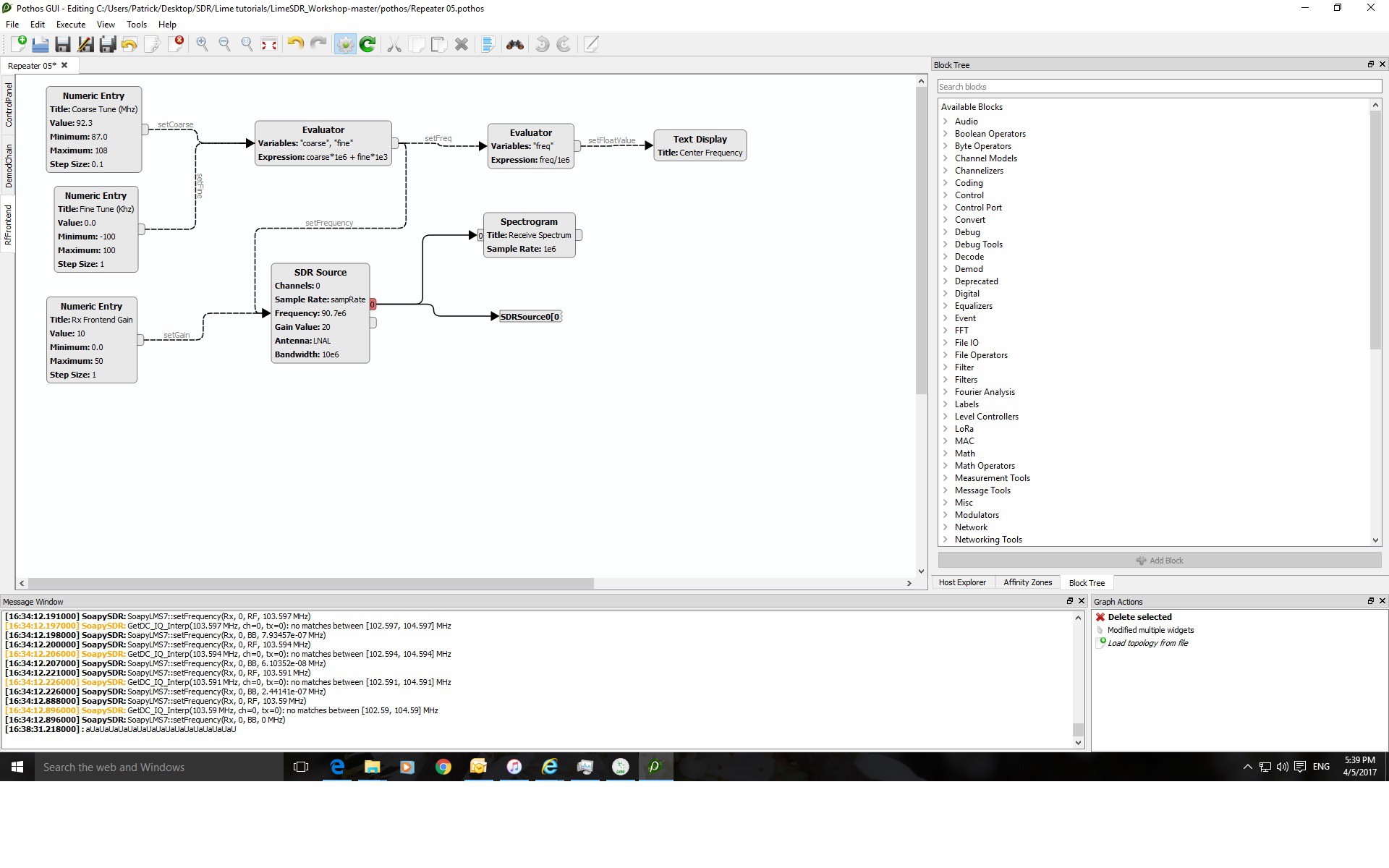
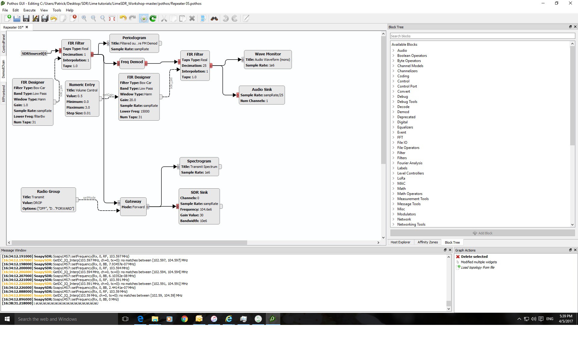
Successful Transmit on FM using LimeSDR and Pothos Software
04/05/2017 at 17:03 • 0 commentsAt last I seem to be getting somewhere with the LimeSDR transceiver. Yesterday I started using Pothos to create an FM radio and today I was able to re-transmit one of my local radio stations to another frequency just before my local telecoms regulator discovered what I was doing.
This is an important step towards producing a proper 4G signal repeater - there's no point in diving in right at the deep end so a simple transmit is a good step forwards.
The Pothos file for this project is here on this Hackaday page under the 'Files' section.
Please could someone tell me why I was getting double transmission either side of the selected frequency? This can be seen on the video below:
![]()
![]()
![]()
-
Learning the LimeSDR Tranciever.
04/04/2017 at 09:32 • 0 commentsWhilst waiting for new antenna cables to arrive, I'll be programming this LimeSDR transceiver to pick up an FM radio station as a learning exercise. I did try using this device as a Femtocell but failed due to the incredible complexity of this gadget and my incredible lack of expertise! There are plans afoot to connect the SDR to an Arduino and carry on learning how to use it properly.
![]()
-
Some small success
04/04/2017 at 09:15 • 0 commentsAt last, I managed to get the 800 MHz frequencies boosted using some cascaded basic power amps and one side of one of the duplex filter:
Tried to replicate it today but one of the antenna cables failed :(
-
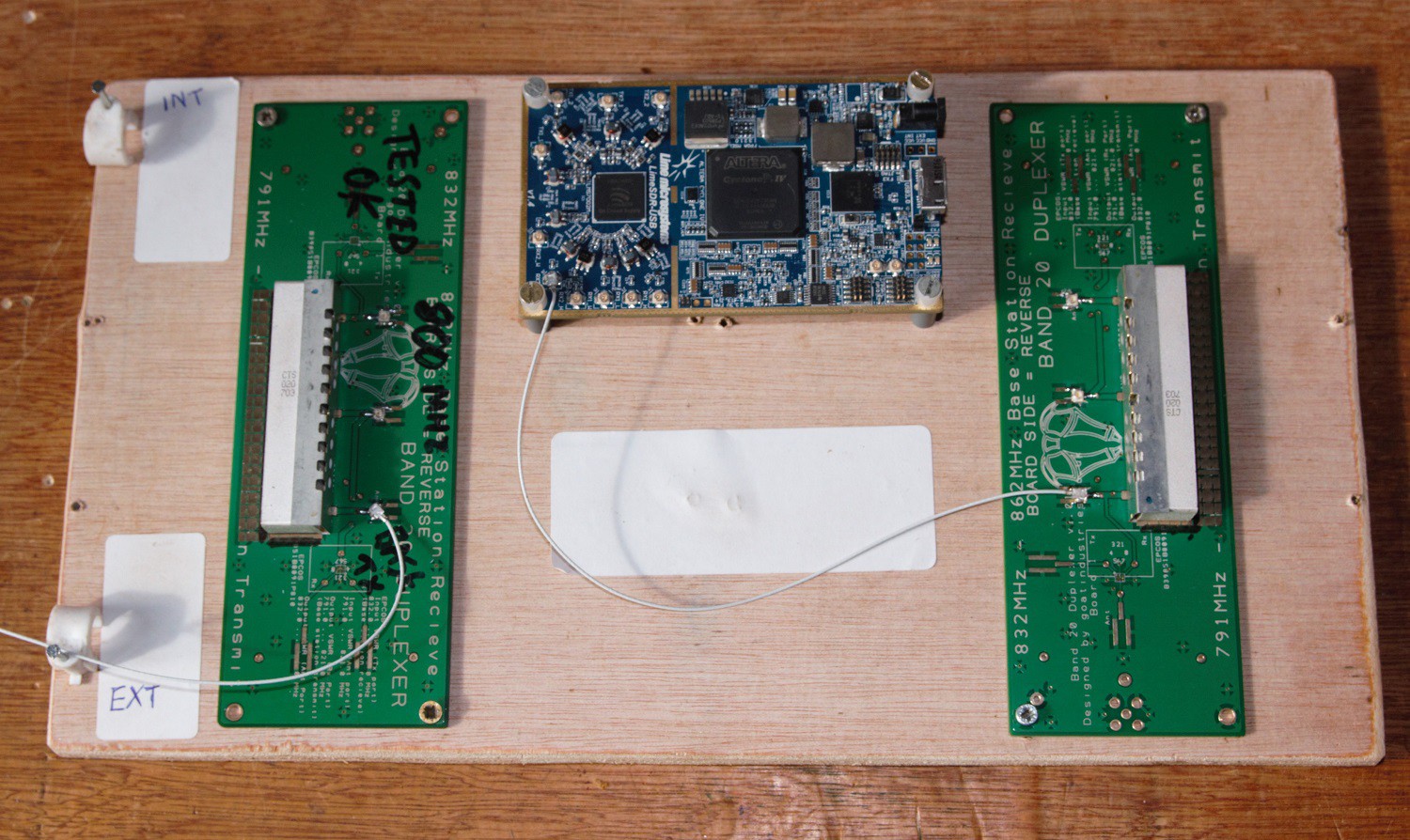
Building and testing microwave duplex band pass filters
03/25/2017 at 14:45 • 0 commentsI decided to try and be a bit more logical in my approach to this project and start building the gadget from the beginning - the band pass filters. Why do we need them? They're to filter out all those FM radio stations etc and provide (hopefully) a nice clean break between the incoming signals and the outgoing ones, which operate on well defined frequency bands eg band 20 base stations transmit on frequencies between 791 and 821 MHz.
![]() Our cell phones, if they're actually using band 20, transmit on 832 to 862 MHz and we don't really want each of our amps trying to process both sets of frequencies at the same time .... And certainly not FM radio stations!
Our cell phones, if they're actually using band 20, transmit on 832 to 862 MHz and we don't really want each of our amps trying to process both sets of frequencies at the same time .... And certainly not FM radio stations!Ok, less of the theory and more of the mechanics. Looking at the actual filter units, the USD020 s from CTS, it looks like they've been attacked by some kind of cyber-kinetic squirrel:
![]()
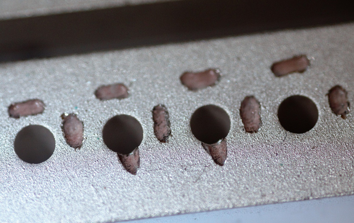
And looking more closely we can see that they've actually been deliberately gouged out with a precision machine:
![]() I contacted CTS, worried that somebody had sabotaged my filters, but they reassured me that this was in fact fine tuning at the manufacturing plant - FANTASTIC!
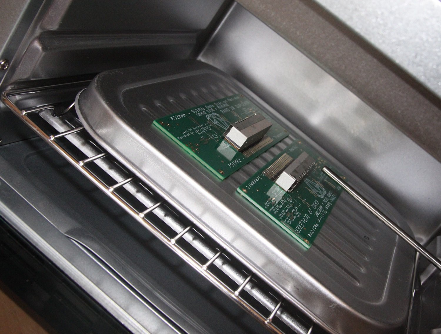
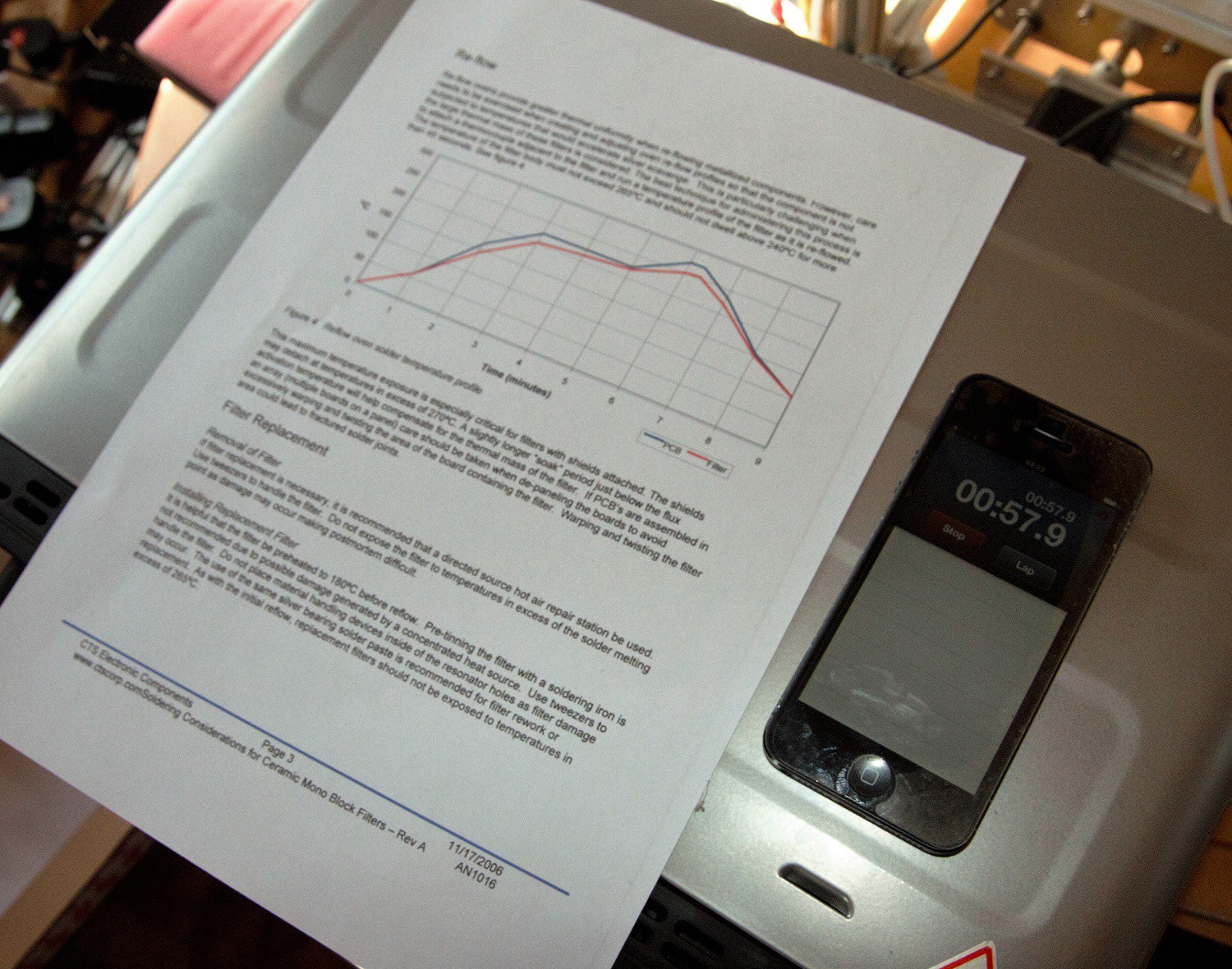
I contacted CTS, worried that somebody had sabotaged my filters, but they reassured me that this was in fact fine tuning at the manufacturing plant - FANTASTIC!So, check, re-check, quadruple check the soldering guide for these beasts and place them on their mini PCBs and into the toaster oven for breakfast:
![]()
![]()
![]()
The filters are heavy blocks of metals so my thermometer probe is going to lag behind the actual readings by about 30 seconds or so by my estimates. In any case, the maximum temperature was not exceeded and it all working out fine - thank God, as these components are not cheap!
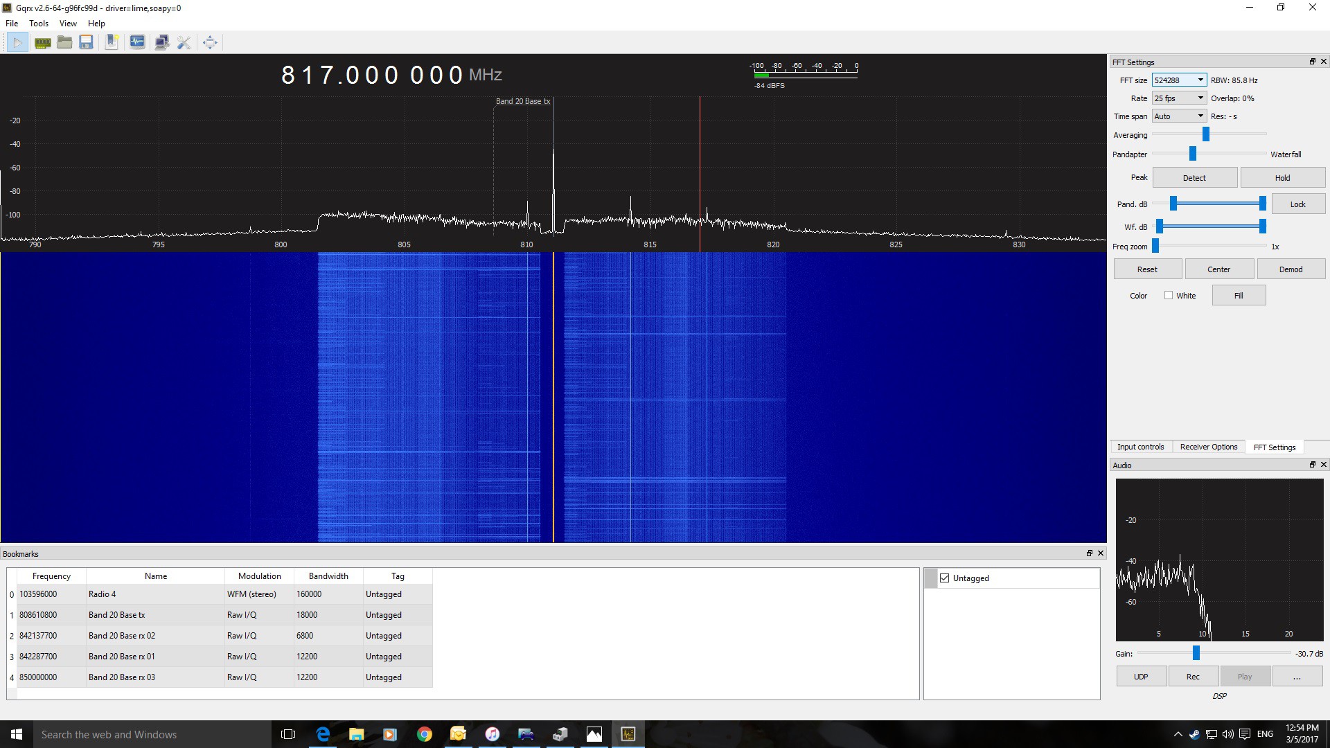
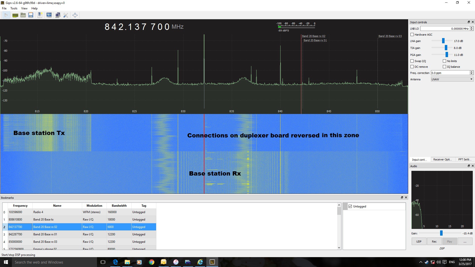
Now for testing on the LimeSDR:
![]()
I paused the FTT waterfall halfway through and changed the filter connections from Rx to Tx and we can see nice clean separation between the two sets of frequencies - wonderful - those cyber-kinetic squirrels did a really good job! Now to solder up the rest of them and test them as well.
-
Building blocks at the initial stages of the project
03/21/2017 at 14:03 • 0 commentsHere are some boards for putting together a basic 4G femtocell.
It would be very tempting to try and design and build a PCB with all the desired features from the very beginning and, in an apparent contradiction, there is actually a final design in progress as well. So what I have done is to split the project up into building blocks, mostly on separate PCBs or using PCBs with different blocks on different sides of the board. Confusing? - Yes, I am very possibly confused about what I am doing as it seems that I am trying to do the initial and the final stages simultaneously! There is however some logic to this, as l will try and explain.
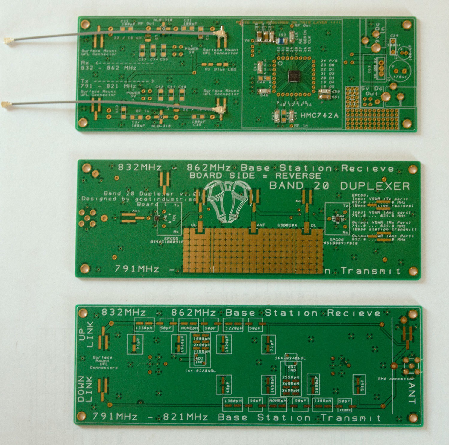
Here below are the building blocks for stage 1 (There are already some more consolidated building block PCBs for stage 2, but I'm trying to ignore them at the moment ):
![]() The top board has a couple of RF amp circuits and a power supply. The left hand RF circuit has a basic amp with no gain control which can be used in series with the other amp or on it's own. The big difference is that it's easy to solder. The middle circuit is another amp but it has digital variable gain control. I had the chip soldered in by a specialist company so that at the very least I had one possible error eradicated. I will try and solder subsequent boards myself and will use this board as a testing reference to compare and check my own soldering with a multimeter or oscilloscope. The two amp circuits were taken directly from the datasheets for the main component so all the passives (capacitors, inductors and resisters) were given by those sheets.
The top board has a couple of RF amp circuits and a power supply. The left hand RF circuit has a basic amp with no gain control which can be used in series with the other amp or on it's own. The big difference is that it's easy to solder. The middle circuit is another amp but it has digital variable gain control. I had the chip soldered in by a specialist company so that at the very least I had one possible error eradicated. I will try and solder subsequent boards myself and will use this board as a testing reference to compare and check my own soldering with a multimeter or oscilloscope. The two amp circuits were taken directly from the datasheets for the main component so all the passives (capacitors, inductors and resisters) were given by those sheets.The middle board has an enormous band pass filter (BPF) pad on it which is factory tuned for high accuracy. It also has a couple of tiny 'cell phone' BPFs professionally soldered on, just to test the difference between the two options, one being big and expensive and the second being ridiculously small and 1/4 of the price.
The bottom board, which is actually the reverse of the middle board, has pads for home made filter circuits with one tunable inductor. This circuit is here just to prove to myself that we can't design and build our own BPFs because of the poor tolerances of the available components (mostly +-5%). It might even work!
The next log will look at another board that is already sitting on my table ready to be soldered up and that has some of the above features combined. Maybe stage 2 will work straight off, but if it doesn't, then I've got stage one as a good fallback. I give stage 1 about 70% chance of success and stage 2 about 50% chance.
One of the problems with working with PCBs like this is that the turn around time for manufacture is 10 days, including postage from China. For this reason it's good to try and be 10 days ahead of myself. Another problem is that some of the components are very hard to get hold of. The large BPFs are made in China for a USA company who only sell through one UK company so the supply chain takes about 3 weeks to navigate.
Cell Phone 4G LTE Repeater / Booster / Femtocell
An outside pole mounted aerial picks up 4G signals which are then filtered, amplified and re-transmitted through a second inside aerial.

 Our cell phones, if they're actually using band 20, transmit on 832 to 862 MHz and we don't really want each of our amps trying to process both sets of frequencies at the same time .... And certainly not FM radio stations!
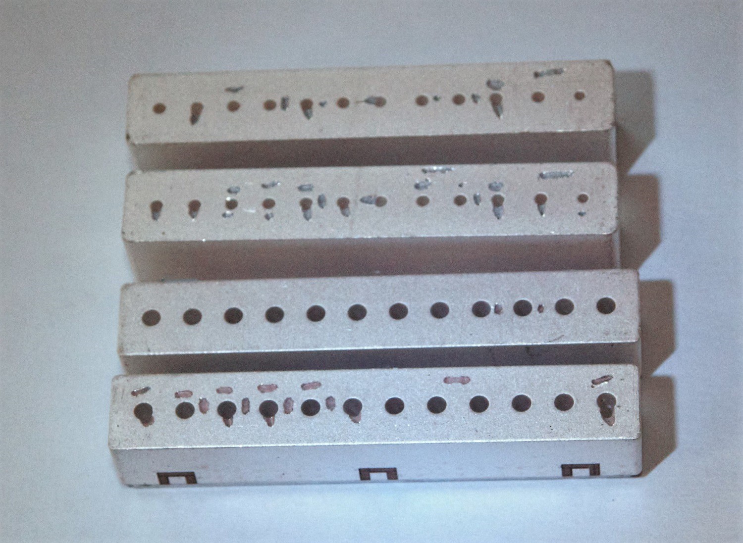
 I contacted CTS, worried that somebody had sabotaged my filters, but they reassured me that this was in fact fine tuning at the manufacturing plant - FANTASTIC!
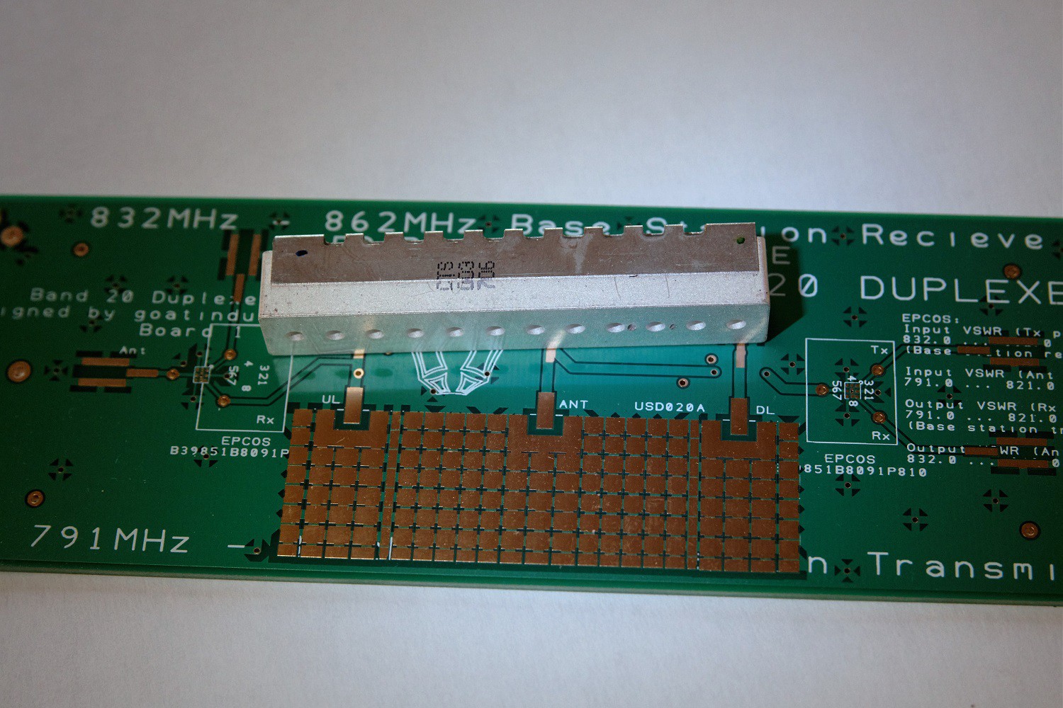
 The top board has a couple of RF amp circuits and a power supply. The left hand RF circuit has a basic amp with no gain control which can be used in series with the other amp or on it's own. The big difference is that it's easy to solder. The middle circuit is another amp but it has digital variable gain control. I had the chip soldered in by a specialist company so that at the very least I had one possible error eradicated. I will try and solder subsequent boards myself and will use this board as a testing reference to compare and check my own soldering with a multimeter or oscilloscope. The two amp circuits were taken directly from the datasheets for the main component so all the passives (capacitors, inductors and resisters) were given by those sheets.