 konstantine
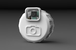
Introducing a camera I created that turns reality into pixel art! 👾📸**
This camera is designed to capture unique, low-resolution, retro-style pixel art photos. Both the 3D model and the code were fully written by me — this is the very first version (v1) of the project.
At this stage, my goal was to create the simplest and most affordable option possible, making it accessible to everyone. I plan to release updates in the future, including an internal battery, a screen, and additional functionality.
To build this current version, you only need 4 parts that you likely already have at home or can buy very cheaply:
components | Amazon | AliExpress |
|---|---|---|
esp32 cam + TTL programmer | ||
6x6mm button | ||
Type-C to 5v | ||
Wire |
🛠 Assembly Instructions (Build Guide)
Here is the step-by-step guide to assembling your own Pixel Art Camera.
Required Tools:
- Soldering Iron (Essential)
- Hot Glue Gun or Super Glue
Step 1: Uploading the Code
Before assembling the hardware, we need to get the "brain" working.
- Connect your ESP32-CAM to the computer using the USB-TTL programmer (the "bottom part" that usually comes with the board).
- Open Arduino IDE on your computer.
- Select the correct board and port, then upload the code provided in this repository.
- Once the upload is successful, disconnect the device from the computer and remove the ESP32-CAM board from the USB programmer unit. We only need the top camera board for the assembly.
Step 2: Preparing the Components
Now, let's get the wires ready.
- Type-C Port: Solder two wires to the Type-C breakout board (Female).
- One wire to the V (VCC) pin.
- One wire to the G (GND) pin.
- Button: Solder two wires to the legs of the tactile button.
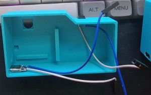
Step 3: Case Assembly
- Mounting Peripherals First:
- Glue the Type-C breakout board into the designated slot on the bottom-left.
- Glue the Button into the slot on the top-right.
- Tip: Make sure the glue is dry and the parts are secure before proceeding.
![]()
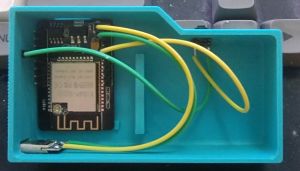
- Mounting the Main Board:
- Place the ESP32-CAM into the case.
- ⚠ CRITICAL CHECK: Before applying any glue, insert your SD card into the slot. Ensure it slides in and out freely and isn't blocked by the case walls. If you glue the board incorrectly, you might not be able to insert or remove the card later!
- Once aligned, secure it with a small amount of glue.
- ⚠ CAUTION: Apply glue only to the corners (top corners and bottom area near the antenna). Do not get glue on the electrical components in the center!
Step 4: Wiring
This is the most critical part. Follow these connections carefully:
- Power Connection (Type-C to ESP32):
- Connect the Type-C V (5V) wire to the 5V pin on the ESP32-CAM.
- Connect the Type-C G (GND) wire to the GND pin on the ESP32-CAM (usually located right next to the 5V pin).
- ⚠ WARNING: Double-check the polarity! Connecting positive to negative will damage the board.
- Button Connection:
- Connect one wire from the button to GPIO 13.
- Note: GPIO 13 is the 4th pin from the top on the side where the 5V pin is located.
- Connect the second wire from the button to any GND pin on the board.
![]()
- Connect one wire from the button to GPIO 13.
Step 5: Power Up!
Once everything is soldered and secured, close the case and put SD card on top left side. Connect the camera to a Power Bank or a USB wall charger using a Type-C cable to start using it.
📖 Quick Start Guide (User Manual)
⚙ How to Turn On & Use
- Power On: Connect the camera to a power source (Type-C cable or Power Bank).
- Activate: After plugging in, you MUST press the button once to wake up the system.
- Shoot: Press the button to take a photo. 1 Click = 1 Photo.
🚦 LED Indicators (What the lights mean)
- 📸 1 Short Blink: Photo taken (Stored in temporary memory/buffer).
- ⏳ Solid Light (Long): Writing photos to...
 Arnov Sharma
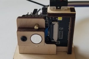
 Dave Ehnebuske
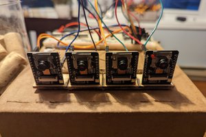
 Bryant
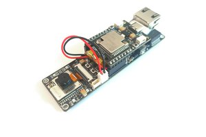
 allexoK