Close
0%
0%

TNY-360: High-Speed Closed-Loop Quadruped Platform

The best Open-Source quadruped robot for learning AI and robotics.

Similar projects worth following

Bridging the Gap Between Toy and Research Grade

I noticed the DIY robotics community is stuck between two extremes:

  • Build a cheap quadruped with "blind" PWM servos that walks like a drunken sailor;
  • Or spend thousands on high-end smart actuators (Dynamixel, BLDC).

I wanted a third option. So, I built the TNY-360: a fully open-source, 12-DOF robotic platform powered by an ESP32-S3 that brings closed-loop control, dual-core real-time kinematics, and a modular hardware ecosystem to the budget DIY space.


The Secret Sauce: The Op-Amp Servo Mod

I refused to use expensive smart servos. Instead, I decided to hack $5 digital MG996R servos to read their internal potentiometers. But anyone who has tried this knows the pain: reading the pot directly draws current, destabilizing the servo's internal PID, and the brushed motor EMI turns your wire into an antenna.
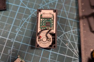


My solution

I designed a custom micro-PCB that fits inside the servo case. It uses an Operational Amplifier (Op-Amp) configured as a voltage buffer. This provides near-infinite input impedance (the servo doesn't even know I'm looking at its voltage) and a low-impedance output signal. Coupled with a software low-pass filter I wrote for the ESP32, I can now achieve clean, 200Hz polling across all 12 legs.


Zero Cable Spaghetti & 200Hz Dual-Core Architecture

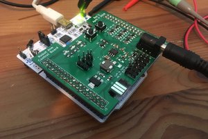
A common point of failure in DIY robots I wanted to eliminate is wiring. I designed a custom modular PCB architecture (Brain, Sensor, Motor, Power) connected via standardized JST-PH cables. I even put the physical dimensions of the robot directly on the silkscreens!


The Firmware:

  • Core 1 (Brain): Handles WebSockets, UI (OLED face animations), and the network stack.
  • Core 1 (Reflex): I dedicated this core to a strict 200Hz loop for kinematics, sensing, planning, and actuating.
  • Smart Calibration: I added physical mechanical endstops. My firmware auto-detects assembly errors and also calculates runtime compensation for backlash and actuator latency.
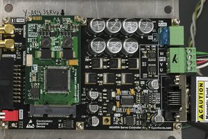

The Power:

I built a custom 3S 18650 battery pack (handling 15A continuous) with an integrated BMS, physical switch, and INA219 monitoring on the Power PCB.


Build it, Code it, Expand it

I also added a dorsal I2C/Power expansion port for custom hardware and created TNY-Coder, a block-based web app (similar to Scratch) so anyone can program the robot and their custom modules visually.

  • The "Twitchy Leg Syndrome" and the Op-Amp Solution

    Paul LOISIL9 hours ago 0 comments

    When I started designing the TNY-360, I knew I wanted closed-loop control. "Blind" PWM servos just don't cut it if you want to do real robotics (calculating inverse kinematics, detecting terrain, auto-calibration). But spending $50+ per smart servo for a 12-DOF quadruped wasn't an option.

    So, I did what every budget-conscious maker does: I bought a bunch of $5 digital MG996R servos and decided to hack them to read their internal potentiometers.

    The internet makes it sound so easy: "Just solder a 4th wire to the middle pin of the servo's potentiometer and plug it into your ESP32's ADC!"

    So I did exactly that. I wired up all 12 legs, powered up the robot, and... it was a disaster. The limbs were shaking uncontrollably, the robot looked like it was having a seizure, and the position readings were clearly unusable.

    What went wrong? Physics.

    After pulling my hair out, I realized the problem wasn't my code, it was the electrical reality of a fully assembled robot:

    • The Voltage Drop: The ESP32's ADC draws a tiny bit of current when it reads a pin. Because the servo's internal potentiometer has a high impedance, drawing that current causes a sudden voltage drop. The servo's internal PID controller panics because it thinks the motor just moved, and tries to correct it. Hence, the twitching.
    • The Antenna Effect: Inside the chassis, my 12 analog wires were routed right next to the high-current power lines and the brushed DC motors. Those wires acted as perfect antennas, picking up massive electromagnetic interference (EMI).

    I realized I couldn't just read the potentiometer directly. I needed an intermediary. Enter the Operational Amplifier (Op-Amp)!

    Instead of a simple RC filter (which wouldn't solve the current-draw issue), I designed a tiny custom PCB that fits completely inside the MG996R's casing. On this board, I put an Op-Amp configured as a voltage follower (buffer).

    The Result

    Combined with a software low-pass filter on my ESP32's "Reflex Core", I can now poll the exact position of all 12 motors at a blistering 200Hz, with zero twitching and buttery smooth movements.

    We turned a $5 dumb servo into a high-speed, closed-loop actuator!

    If you want to see the exact schematic of this micro-PCB, or if you want to mod your own servos for your projects, I’ve documented the entire step-by-step process on the project's website:
    See the servo mod

View project log

Enjoy this project?

Share

Discussions

Similar Projects

Does this project spark your interest?

Become a member to follow this project and never miss any updates