See a series of logs with overview of the project:
0%
0%
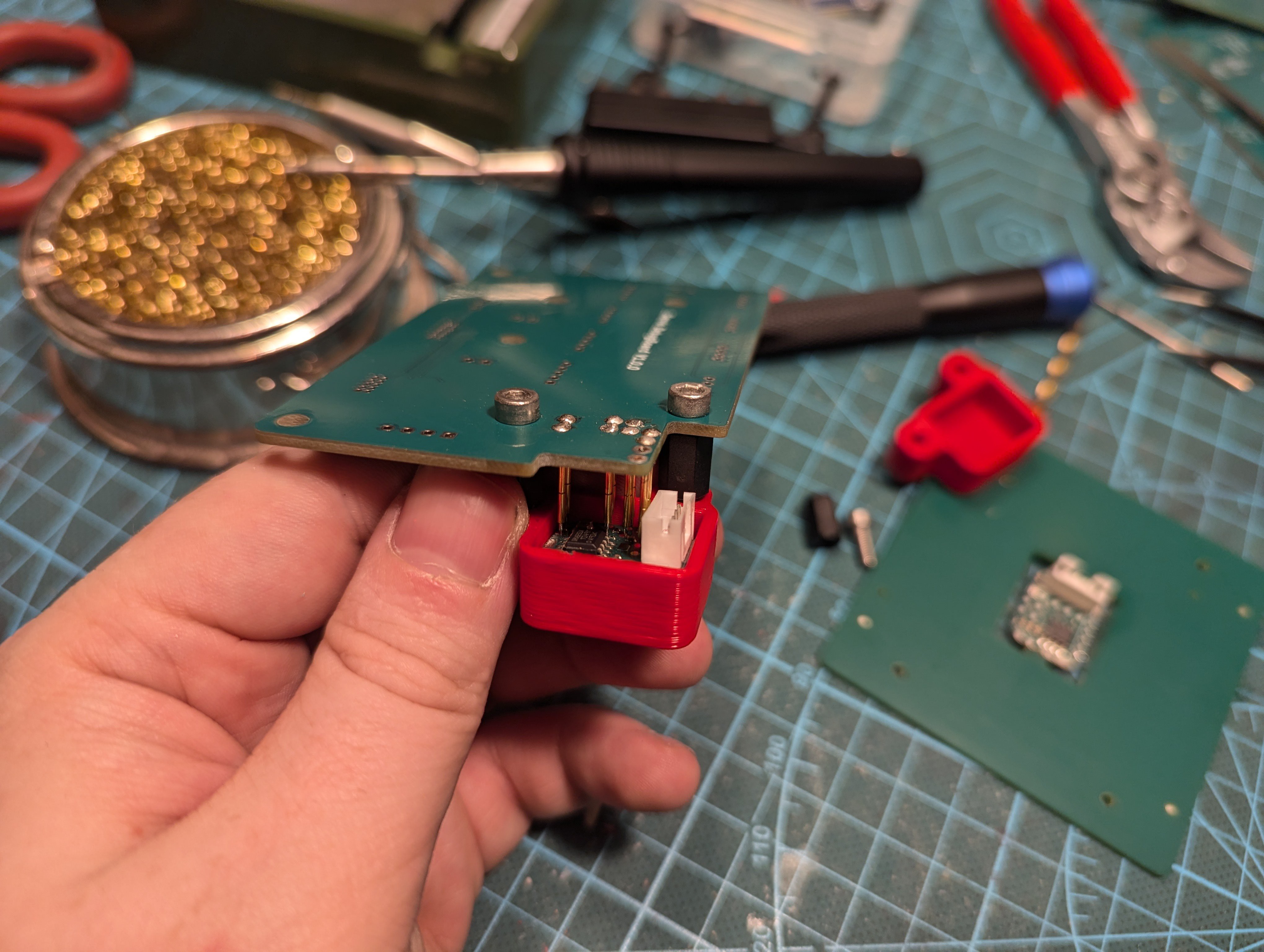
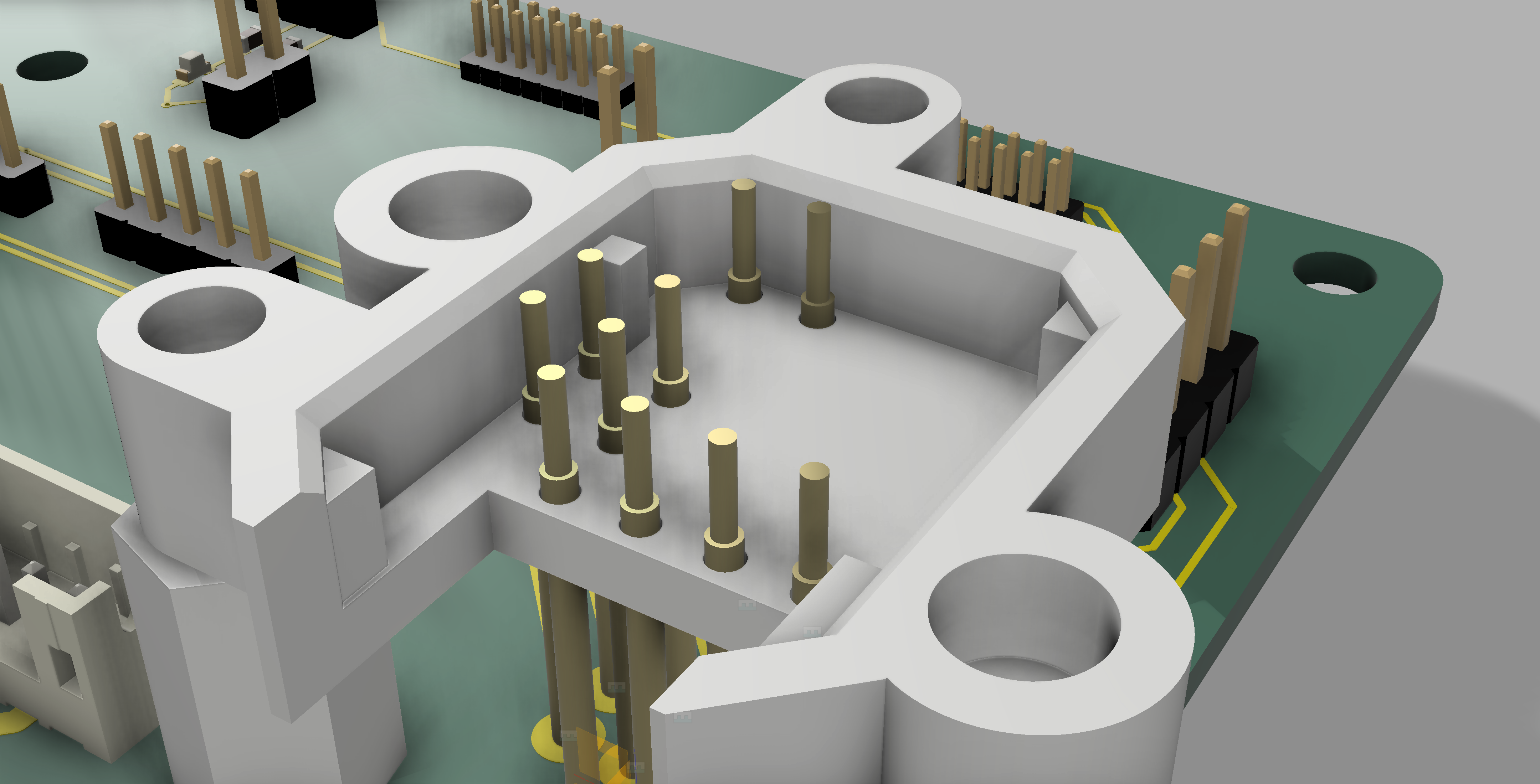
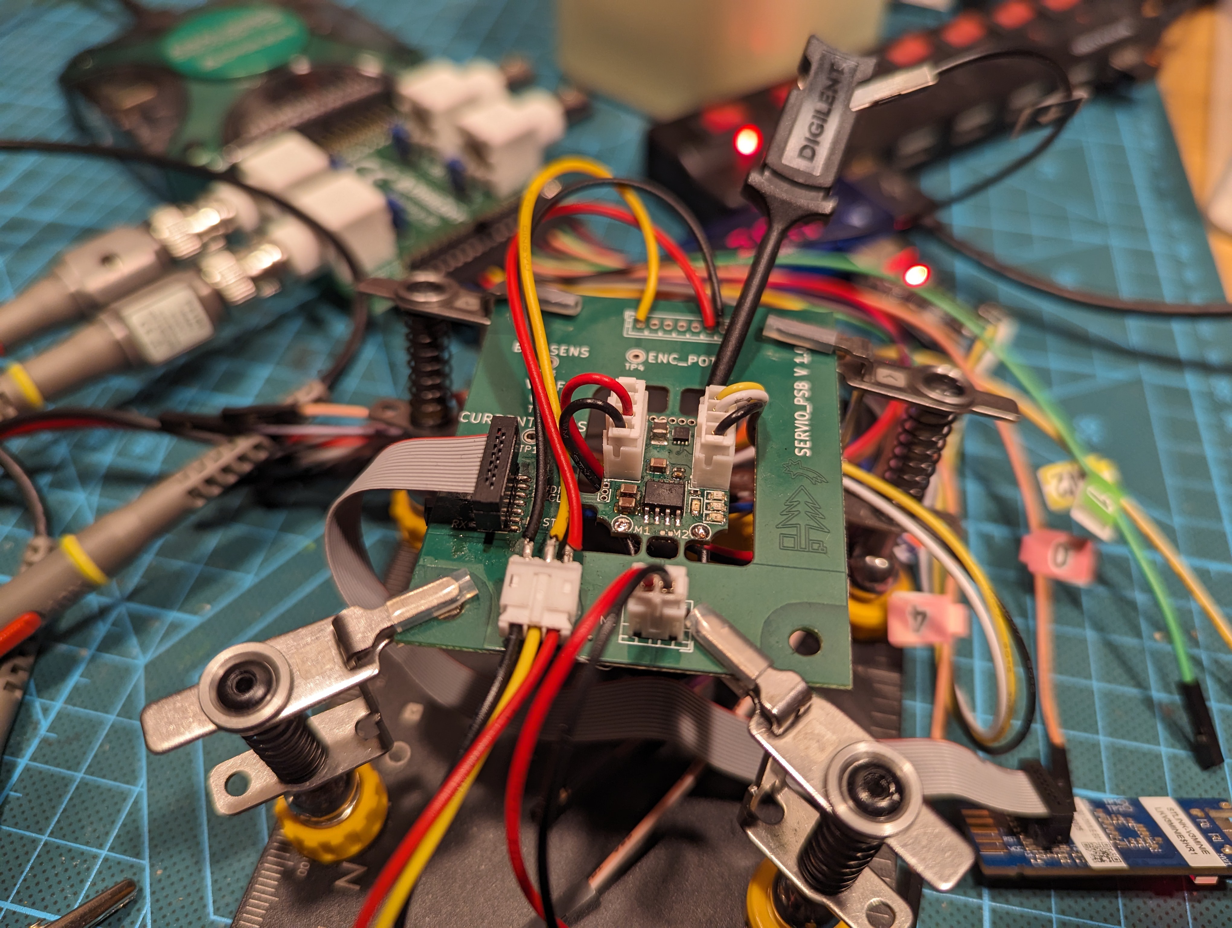
Servio
Open-source DC servomotor with extensive testing infrastructure.
Become a Hackaday.io member
Already have an account? Log in.
Just one more thing
To make the experience fit your profile, pick a username and tell us what interests you.
Pick an awesome username
hackaday.io/
Your profile's URL: hackaday.io/username. Max 25 alphanumeric characters.
Pick a few interests
Projects that share your interests
People that share your interests


 Jarrod
 pat92fr
 Anthrobotics
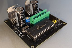
 JP Gleyzes
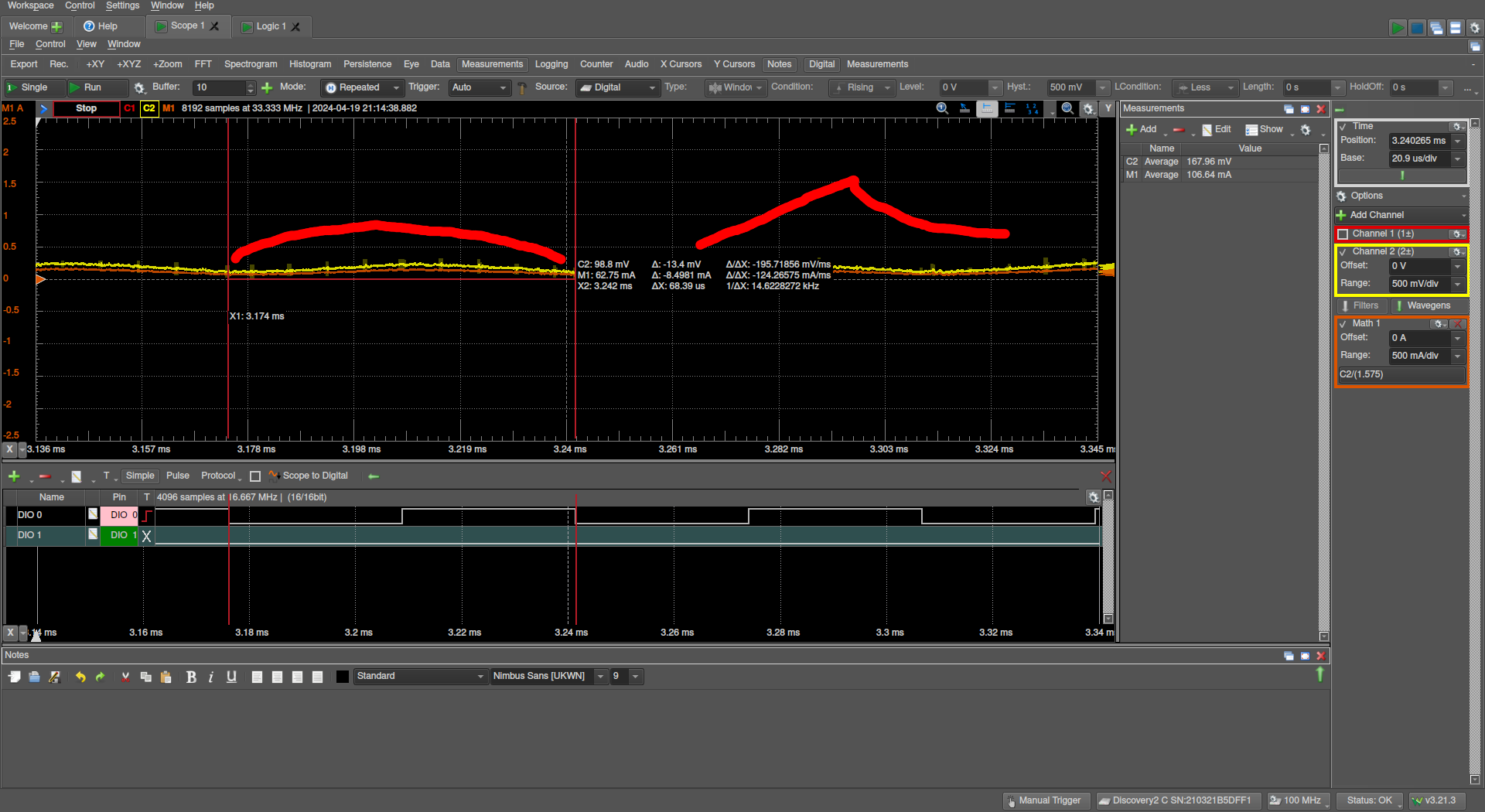
Your measured current might be proportional to the PWM value if you replace the motor in your test setup with a low inductance resistor. Pick a convenient value to convert the resistor voltage to current like 1 Ohm. This would allow you to test the current sense system in a linear environment.
The current drawn by a motor is related to the PWM value and the motor speed. Turning a DC motor with some external force (or just inertia) generates a DC voltage. That DC voltage is also generated when you are driving the motor in a normal motor configuration. That voltage is called Back EMF. It is proportional to the speed of the motor. It is also opposite polarity of the voltage that is driving the motor. As a result motor current is related to motor speed for a given voltage.
Imotor = (Vdrive - VbackEMF)/Rmotor
If you think about the case where the motor is stopped, VbackEMF will be 0 and your motor current will be Vdrive/Rmotor.
In a frictionless configuration, Vdrive will equal VbackEMF and the motor current would be 0.