veverak
-
Batch of 25
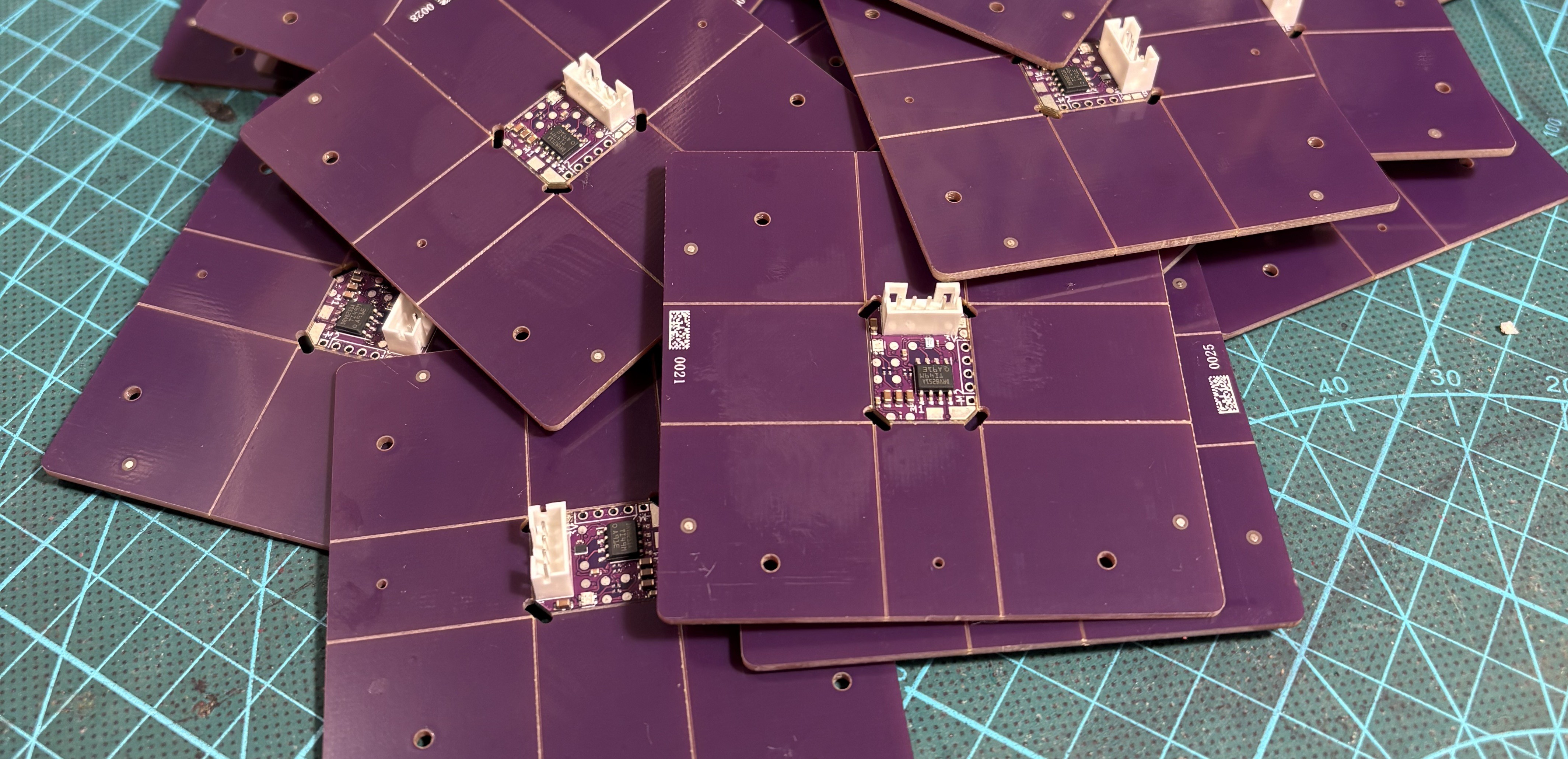
11/03/2025 at 18:31 • 0 commentsThis project indeed got sideload a bit by me changing work and having more demanding work, but have I forgotten? NO! have I delayed this a bit? yes, did I finally get a batch of 25 pieces that can be heavily used for testing? or prototypes? Y E S
![]()
-
Beta goes to friend
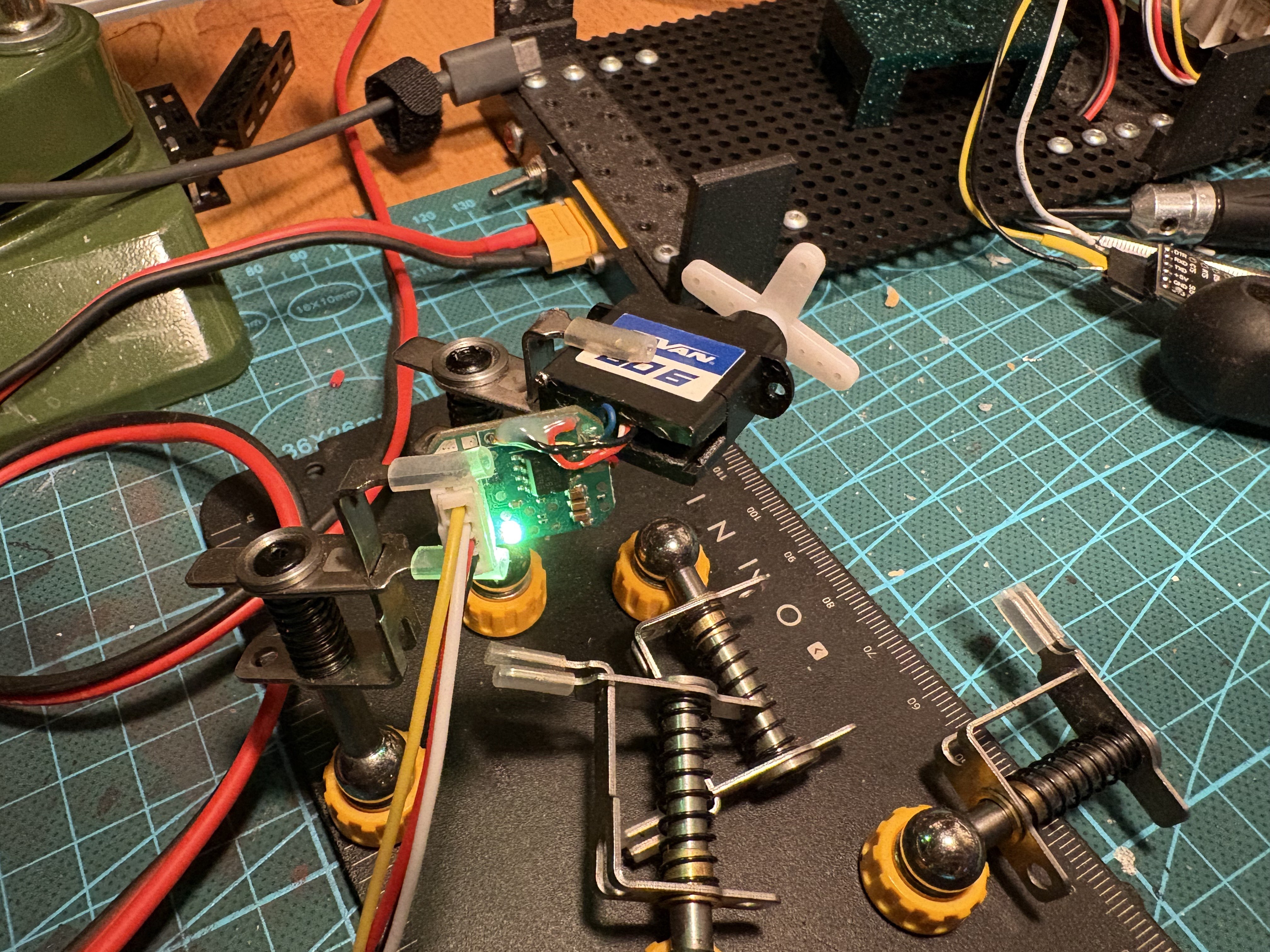
07/24/2025 at 16:14 • 0 commentsThese logs kinda slowed down, but finally an important milestone was hit. One set of servio with servomotor was delivered to a friend of mine for beta-testing. I hope it goes well :)
![]()
-
Beta version
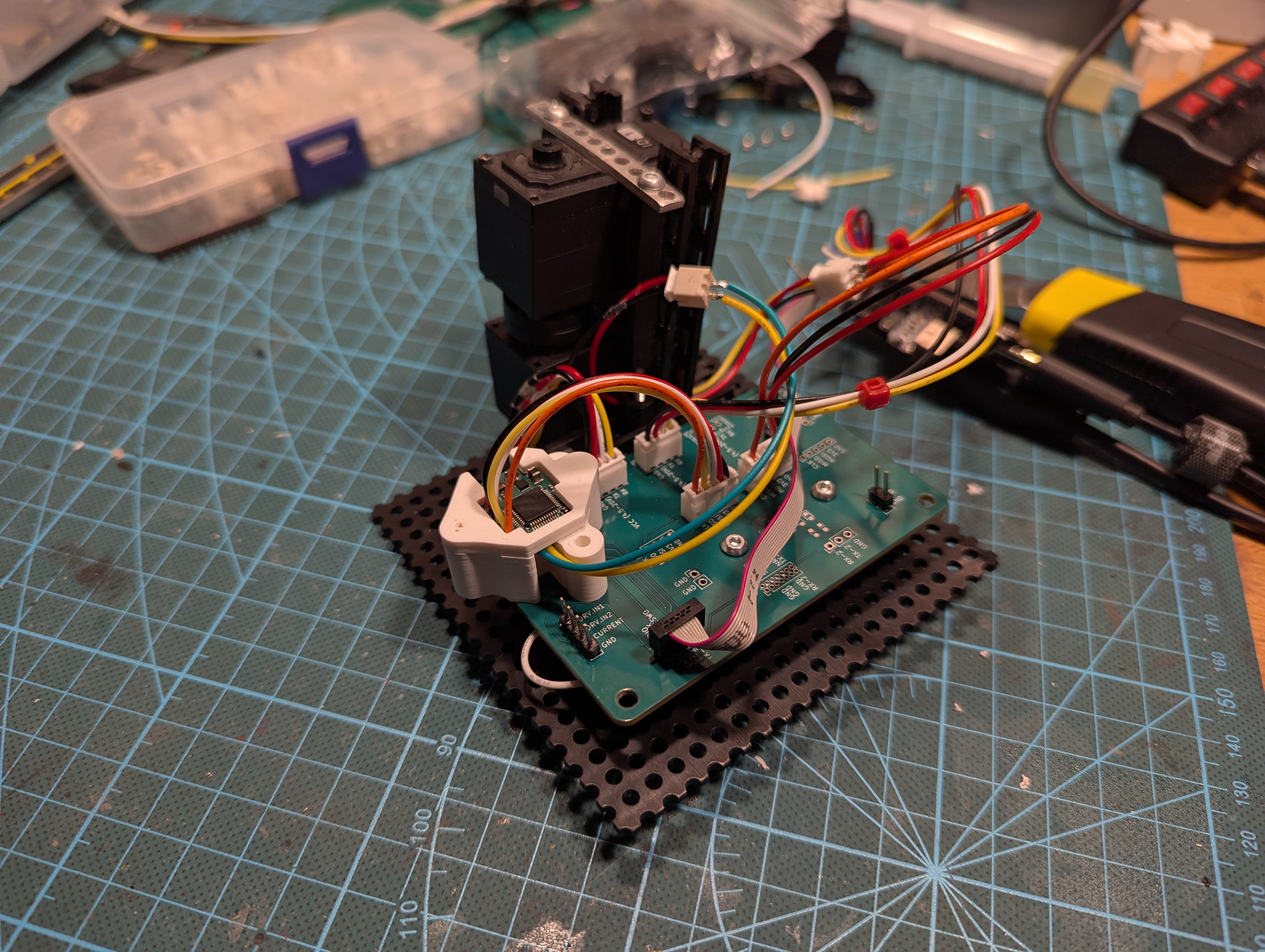
04/25/2025 at 21:49 • 0 commentsWe got a new iteration of the board! (This one will be the final one, right? right?)
We required mostly standard iterative updates to the design. The interesting change for future users is flashing of the firmware over UART - we are now able to flash firmware over the same UART that is used for communication with the servo.
![]()
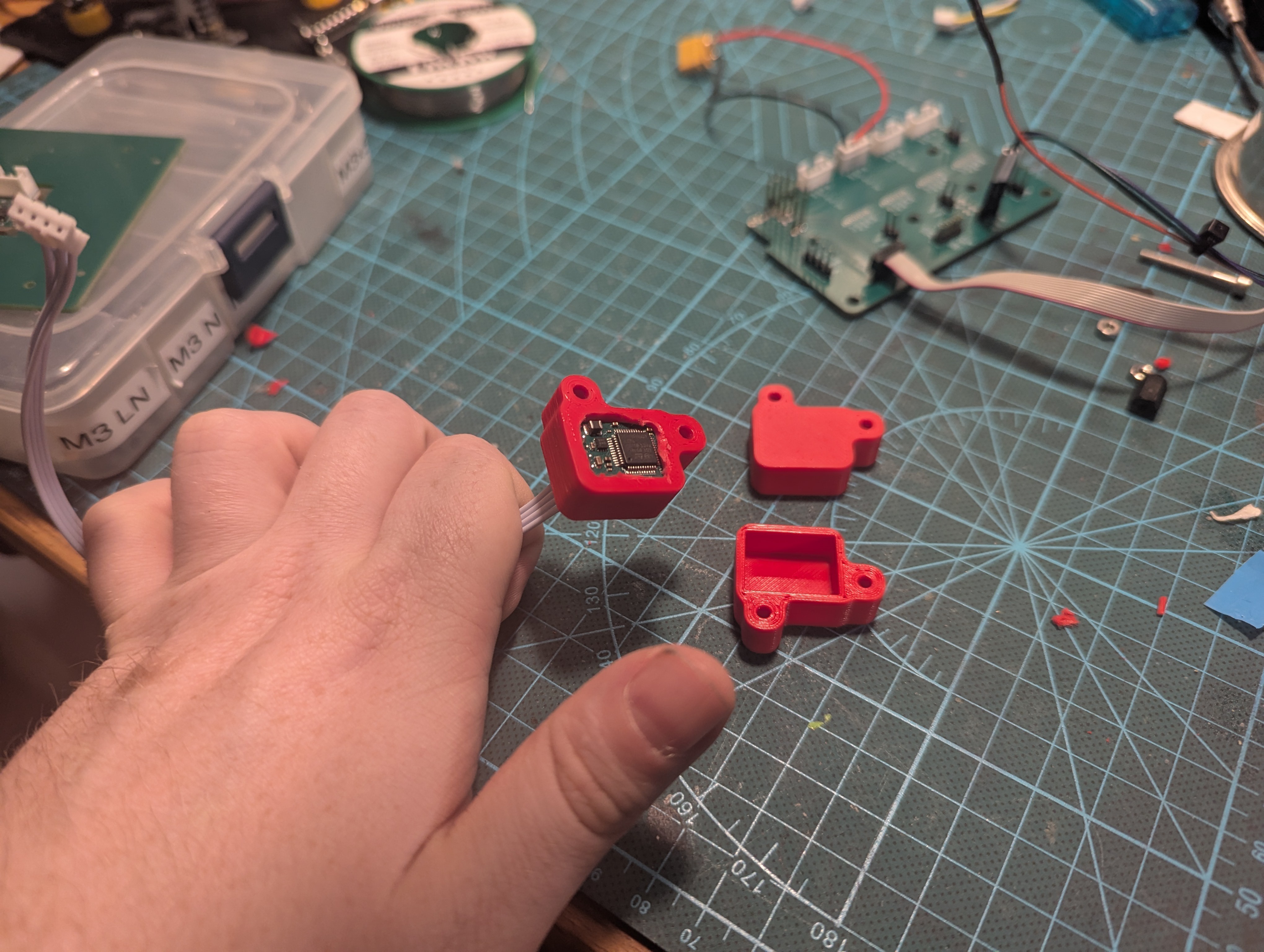
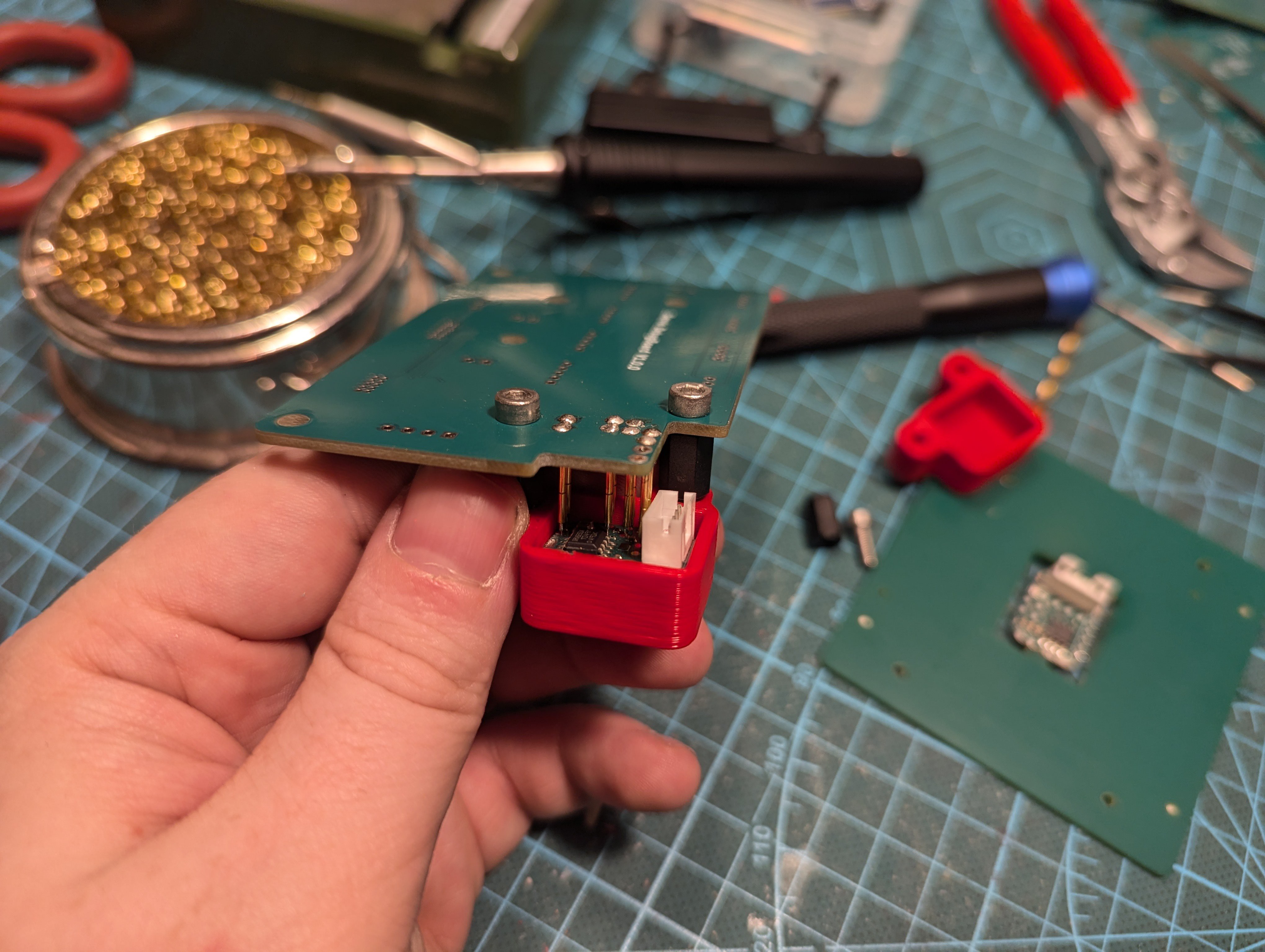
Note that this required a new plastic holder for the testjig and pogopins. I believe I am getting better and better at iterating these.
LX15D
Thanks to historical projects, we got plenty of Hiwonder LX15D servomotors lying around. These are used heavily for the project. Let's integrate servio into that.
![]()
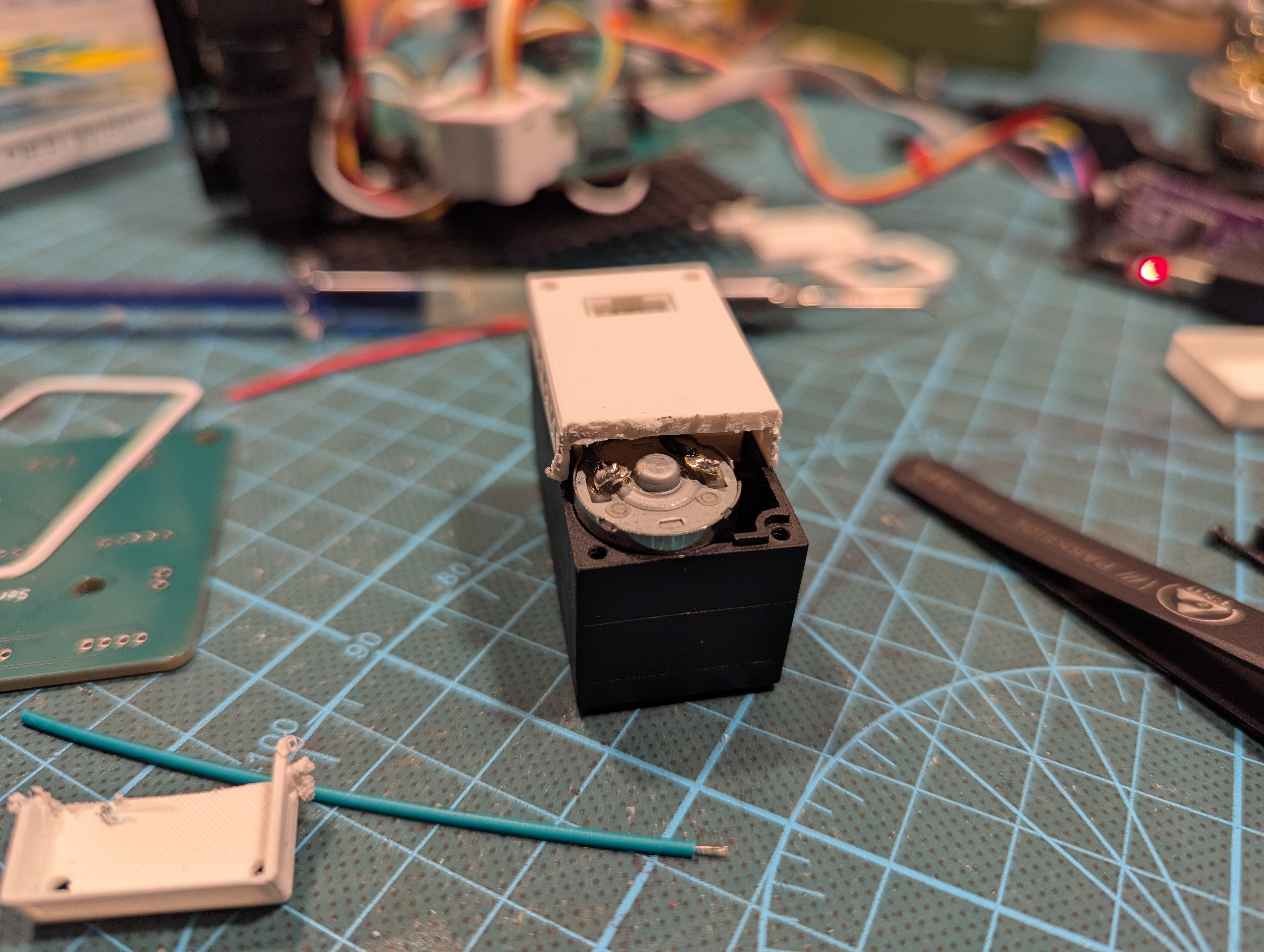
I've got a good feeling about this. The servio fits quite well into the basic plastic insert, and I even managed to create the part self-tensioning. See the bottom wall of the insert - it bends around the motor to create pressure so it sticks in place.
![]()
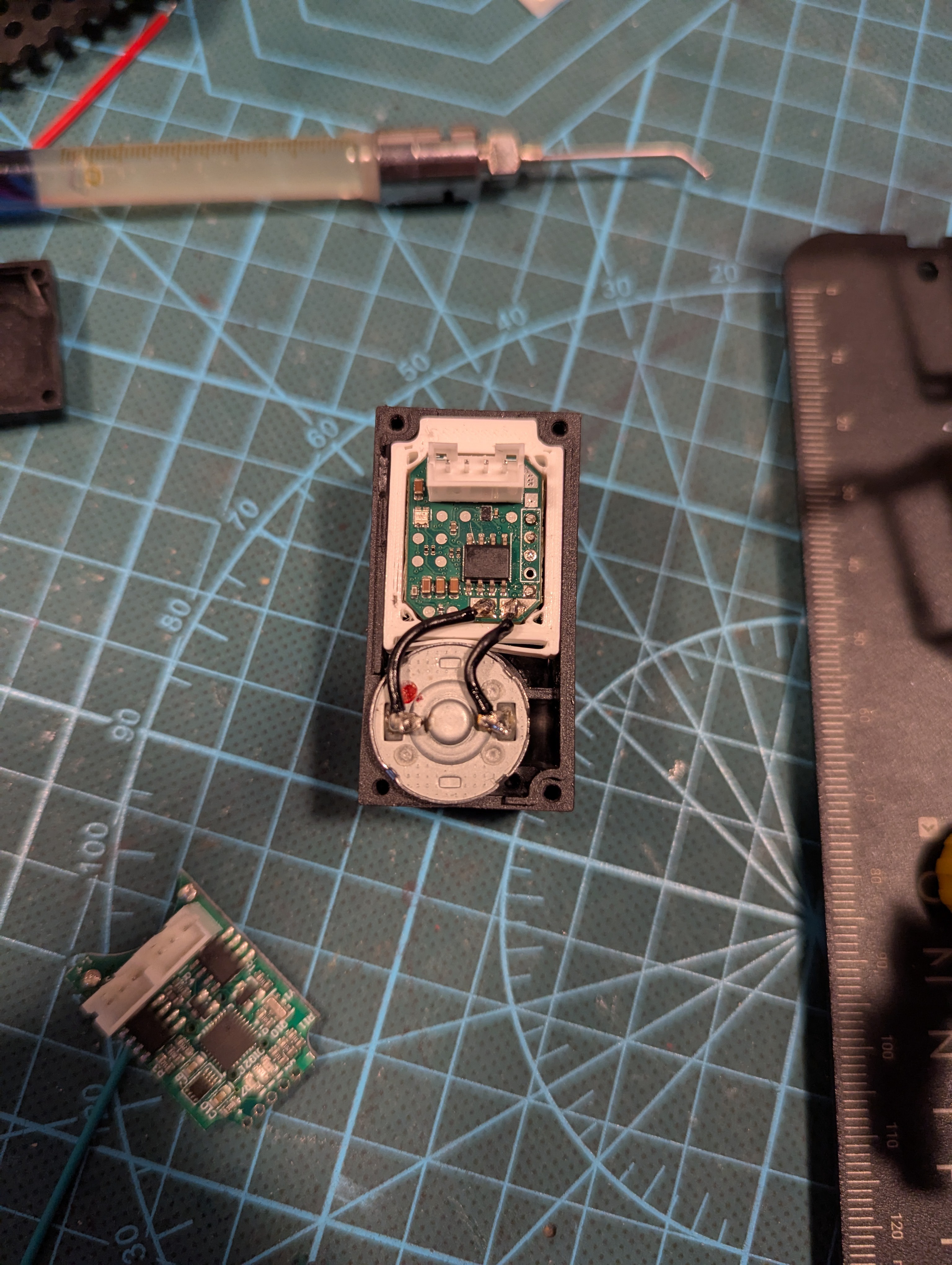
After printing the first iteration of the back-seal for the servo itself, I split open the casing to see how much space is left - enough! So let's make it smaller.
![]()
As the saying goes, it blinks, it ships!
-
From protobuf to text protocol
01/13/2025 at 20:37 • 0 commentsOne of the earlier decisions that had to be made was: what communication protocol should we use for servio?
The two options I've thought about were:
- Protobuf
- Text based
I opted for protobuf as I had previous experience with it and seemed as simple solution. I liked the idea of having instant-support from multiple languages, as I do not want to write libraries for interfacing with the servomotor. The main downside of protobufs was that it would not be trivial for Arduino users to interface with the servo - it seems protobuf are not yet easy to use there.
I was 60% in favor of protobuf, 40% in favor of text-based. The main bummer with text-based protocol was that I was pretty aware that parsing of text is non-trivial.
Change
That decision was changed recently and Servio is from now on text-based, why?
- I worked for more than one year as developer of compiler front-end, with hand-written lexer and parser
- I switched to Mac in my personal life and found out that projects protobuf+nanopb setup just did not worked on Mac
It happend somehow like this: After putting some hours into struggle with making everything work on mac I asked myself: is it really worth it? as much as protobuf is cool is not perfect and evidently I have to waste time trying to make it work on any platform. In the meantime I managed to write more complex data parsing at work reliably, so writing custom lexer/parser is not THAT hard...
One weekend later and Servio got it's text protocol!
Note: I do realize that this might not be the most productive decision ever, but this is still hobby project so there has to be some fun in it.
Goals for text protocol
The content of text protocol should more or less just mirror the content of protobufs. The goals are as follows:
- It should be easy for users to write commands for the servo
- It should be easy for users to parse the responses
That is, we need benevolent and friendly parser of what users send to the servo, but at the same time we have to be quite picky/careful about what we reply to the users - have robust input parsing, but very strict and easy to parse output.
Input
I've picked cmdline-like syntax for the input system, telling servo to switch to position control with goal 0 is just following null-delimited string sent over UART:
mode position 0
Asking servo for property position:
prop position
Querying value of configurable variable current_loop_i:
cfg get current_loop_iThe endgoal is for this to mirror API of most cmdline arguments in bash, as these should be trivial for users to write. This should satisfy the goal of this being simple for the user.
Output
All answers from the servo are _valid JSON_. The root item is always _array_ and first item is always _string_ of value "OK" or "NOK", in case the command should return data, they are added as more items in the array. The string is always null terminated.
Here is an example of exchanges between servo and client:
> mode position 0
< ["OK"]
> cfg get current_loop_i
< ["OK", 42.0]
> prop mode
< ["OK","position"]
I assume that on any platform it should be easy to get somehow decent JSON library, and frankly, for most scenarios hand-parsing this limited subset of json is also feasible.
The important part is that we do not say that output is just JSON, we also constrict its structure.
Testing
Given that this was pretty dramatic change, how was this ... verified?
Parsers/Lexers had the strong benefit that they are extremely easy to unit test - you just prepare bunch of strings as input and verify whenever the text was parsed correctly.
What is worse is to make reliable component test. Internally Servio uses concept of "dispatcher" - component which:
- Takes input from the user
- Applies it to the system
- Provides response
I figured that there are no host-executable tests for this, as dispatcher interacts heavily with HW, and decided to rectify that... and frankly, it turned out to be easier than expected.
Servio already tried to abstract implementations from hardware specific drivers by using plain old interfaces, the task was just to implement mock-versions of various hardware connected to the servo:
        drv::mock::pwm_mot mot;
        drv::mock::pos     gp;
        drv::mock::curr    gc;
        drv::mock::vcc     gv;
        drv::mock::temp    tm;
        drv::mock::stor    sd;
Writing 6 mocks was not really hard, and all that was necessary after that is to setup the core facility of servio (already abstracted into "core") and unit-test usage of dispatcher against it.
The test cases following that looked something like this:
        test( "mode power 0.2", R"(["OK"])"_json );
        EXPECT_EQ( cor.ctl.get_power(), 0.2_pwr );
        test( "prop mode", R"(["OK", "power"])"_json );
Each call to `test` gets an input, shows it through the dispatching system and checks that expected answer matches. Following that is some simple checking whenever the message had expected effect on the system.
I guess the number of tests is not optimal yet, but it clearly shows that it is easy to get more :)
-
v3 board
12/23/2024 at 14:52 • 0 commentsYaaay! got a busy year (wedding and stuff) and finally got back to this project again. Thanks to T.V. we got another iteration of the board.
![]()
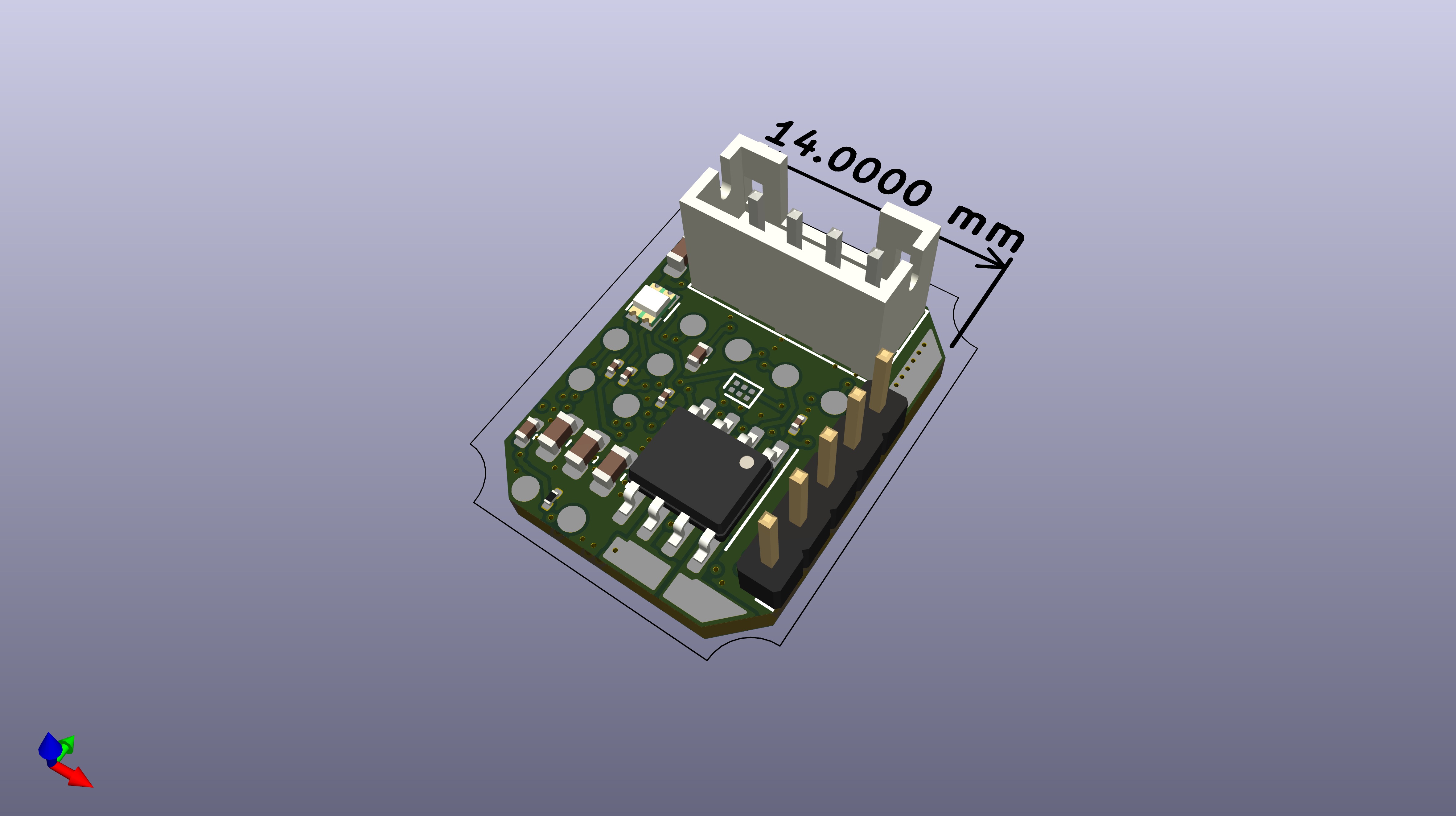
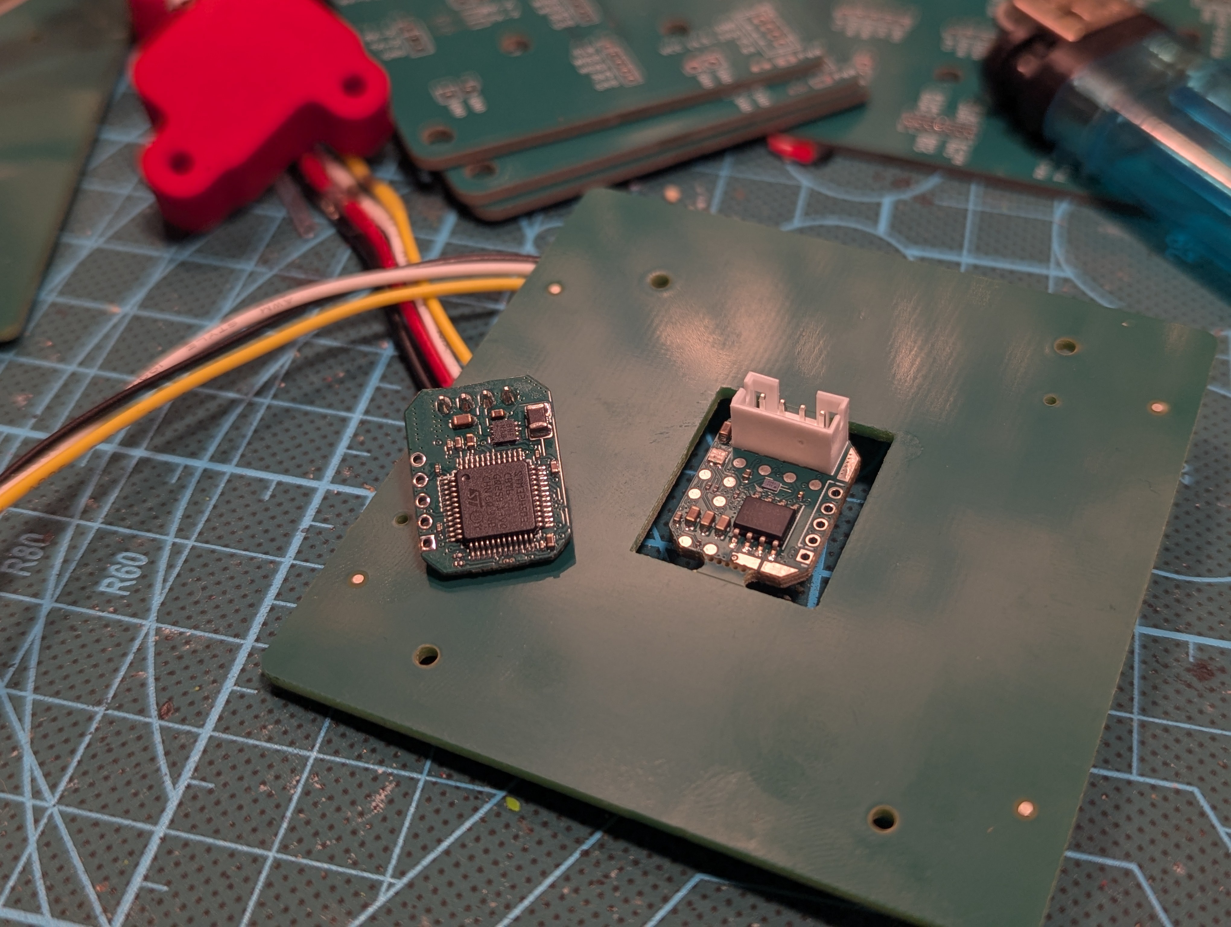
The new design is tad bit smaller and with some iterative changes. The main goal was to get rid of directly connected debug board and move to pogo pins, ideally this should've been the final version. (Obviously it is not) Out of the new features: we got i2c memory chip! no need to play with internal flash anymore.
![]()
Testjig
First version of testjig proved to be impractical, the idea was to create a "cap" that encapsulates the board, this did not work great:
- The board was not accessible for attaching debug probes/stuff
- The alignment of pins was not perfect
- The board tilted a bit inside under the pressure from the pins
![]()
![]()
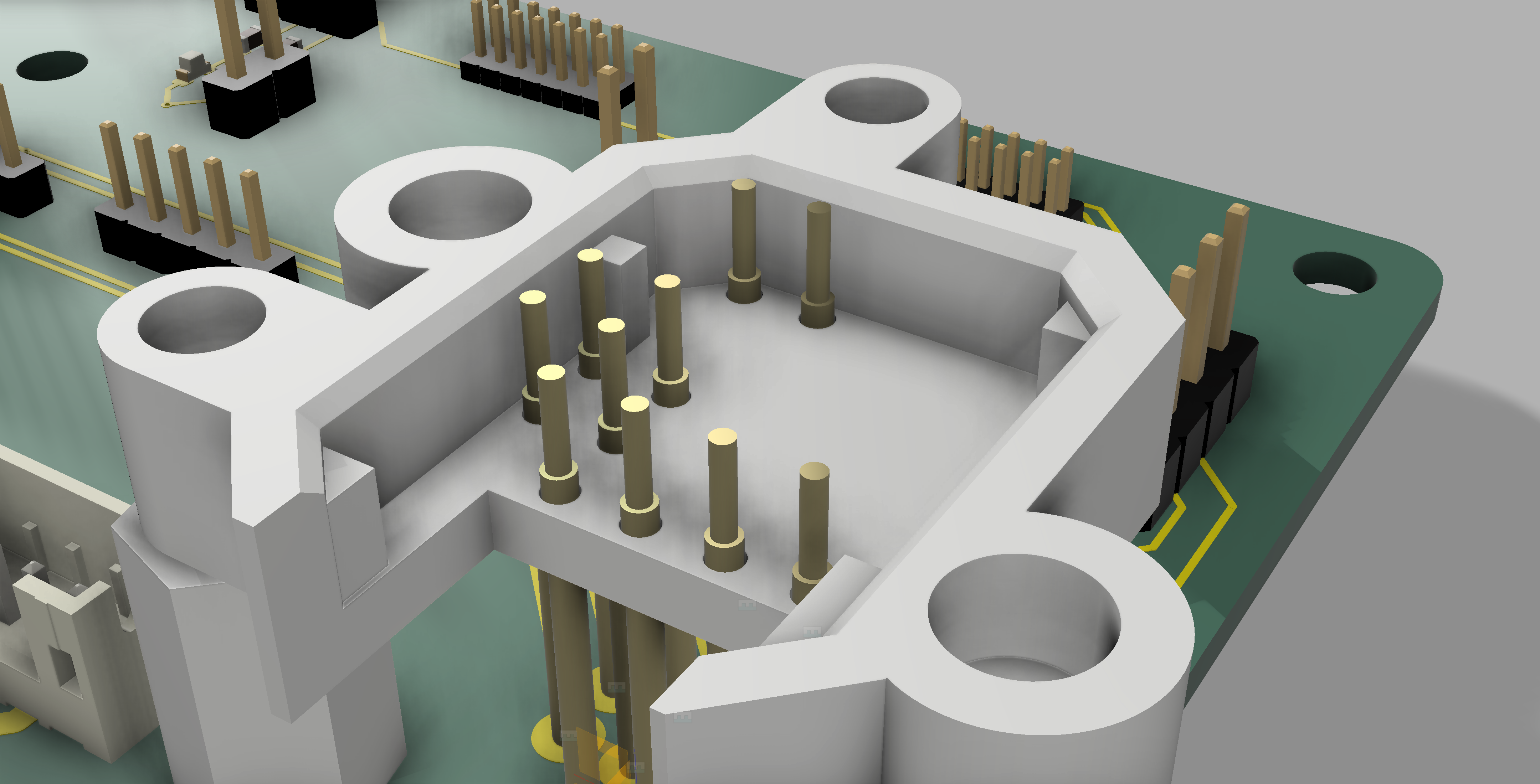
I think that the root cause is the idea of the cap. Instead I started remodelling the holder into two-part system - there will be part holding the PCB from the bottom side and part holding it from the top site. Both will be connected together to hold all in place (magnets?)
![]()
Hopefully I can get this over soon over the holidays and soon got to programming this thing! :)
-
Current sensing analysis - (Part 2/2)
04/18/2024 at 06:20 • 0 commentsFinally, I had some time (and friends) to investigate what's happening with current sensing.
In Part 1, I made four interesting observations, but only deserves a response: Yes, it's normal for the voltage on the current shunt to be non-zero. (At least, that's what I was told) This is still problematic and has to be investigate further.
This time, I've altered the way the H-bridge is controlled, conducted additional measurements, and added even more measurements on top of those.
Switching mode
Let's summarize how the H-bridge controlled the motor: it drives the motor based on two digital input pins. The specifics vary with each H-bridge; what we used was:
- 01 input drives the motor in one direction.
- 10 input drives the motor in the opposite direction.
- 00 input is used when the motor should be idle.
I realized he might be onto something, as this is exactly what the datasheet recommends. Why? In 00 mode, the motor pins are not connected to anything. In 11 mode, the motor pins are shorted together.
To achieve gradual control, we use PWM. With a 25% duty cycle, we spend 25% of the time in the 10 state and 75% of the time in the 00 state.
A friend of mine, J. Mrazek (thanks!), suggested that this was not optimal and that I should switch between the 10 and 11 states instead. That is, one more option:
4. 11 input when the motor should not be idle.
After reviewing the datasheet of the DRV8251A, I realized he might be onto something, as this is exactly what the datasheet recommends. Why? In 00 mode, the motor pins are not connected to anything. In 11 mode, the motor pins are shorted together.
I won't detail all the consequences, as I'm not certain about them, but there is one practical aspect I can work with: in 11 mode, I can measure the current flowing through the motor (thanks to the internal current sensing of the H-bridge).
The way I see it, switching between 01 and 11 modes allows the 01 mode to let the current flow into the motor, while the 11 mode shows how it circulates inside—both providing good insight into the torque applied by the motor, which is the real value I'm interested in.
Current readings with H-bridge in 01/11 mode
Let’s measure all the data again! We'll use the same table as in Part 1, so please refer there for an explanation.
power 0% 25% 50% 75% 100% power source current 14mA 45mA 83mA 130mA 170mA R7 voltage 25mV 172mV 210mV 245mV 267mV calculated motor current 15mA 109mA 131mA 156mA 169mA This time, the data table showed anomalies; the voltage on pin R7 no longer scaled linearly with the PWM duty cycle, which was baffling. This issue perplexed me for a while, and I was on the verge of discarding the H-bridge as this seemed bonkers.
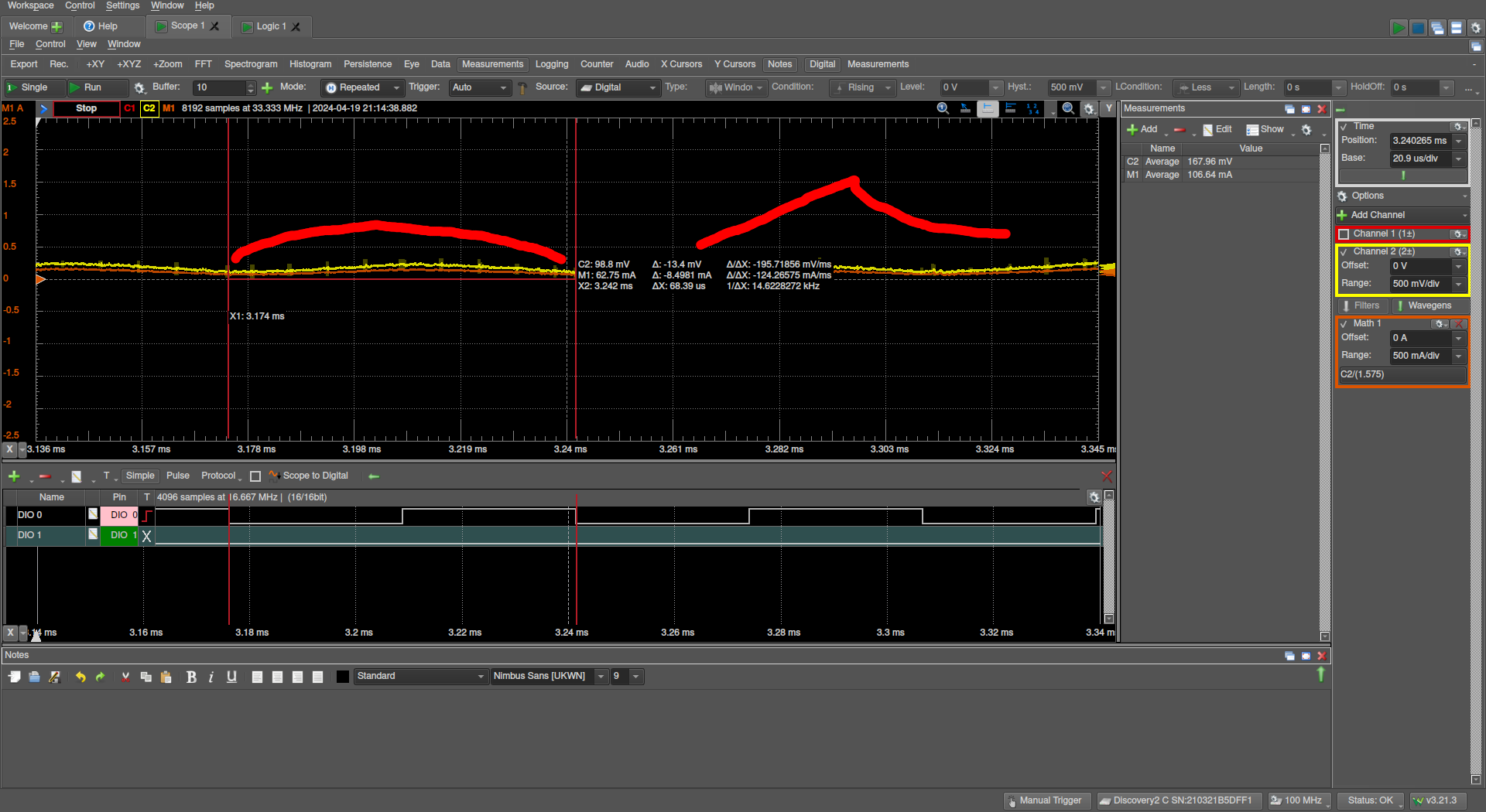
In an attempt to understand what was happening, I also captured a screenshot of the voltage profile to observe how the voltage on R7 changed during the duration of one pulse.
![]()
As my modest drawing skills illustrate, the new measurements reveal significant changes in the voltage profile. The large red shape on the left, representing the current state, shows a symmetric rise and fall in voltage. On the right side, you can see the profile from previous measurements (using 01/00 mode). The difference is striking: in 11 mode, the voltage on R7 decreases much more slowly than in 00 mode, resulting in higher measured current per period.
The central question remains: why has the current stopped behaving linearly?
I understand that the PWM duty cycle and current might not scale linearly, but the non-linearty is too big.
Current readings with H-Bridge in 01/11 mode + current probe on scope + different power source
We managed to borrow a high-quality current sensing probe from a friend—far more expensive than I'd typically invest in hobby equipment. With this, we were able to measure the current flowing through the motor. Unfortunately, I didn't take any pictures of the experiment, so there are no images to share this time.
power 0% 25% 50% 75% 100% power source current 0.01A 0.05A 0.09A 0.13A 0.18A R7 voltage 20mV 190mV 232mV 262mV 290mV current probe 0 A 80mA 100mA 108mA 115mA Note that the current probe showed 0A at 0% duty cycle simply because we calibrated it this way. Nevertheless, it's clear that what I observed on R7 isn’t as nonsensical as it initially seemed; in fact, it accurately reflects reality. The current flowing through the motor does not scale linearly with the PWM duty cycle—or does it
Thanks goes to J.M. who realized what is going on: physics
![]()
As you can see, in my setup, the motor is free-spinning—there is no load opposing the rotation. The motor has a natural limit of rotational velocity based on voltage. Typically, free-spinning motors easily reach their maximum velocity.
This is precisely what occurs in my measurements: the current flowing through the motor does not scale linearly with the duty cycle because the servo motor achieves its maximum velocity too easily, using only a small amount of current. Once it reaches this velocity, no additional current is drawn, regardless of increases in the duty cycle.
How can we be sure? Well, J.M. had a brilliant idea to test this. We took a small DC motor and fixed its shaft so it couldn’t move. Sure enough, with this setup, we observed that the current scales linearly with the duty cycle. (Of course, I didn't take screenshots of this data either).
Conclusion? Current sensing works! \o/ (kinda)
Takeaway
Although we confirmed that everything functions well, there are some crucial observations I need to consider for future work.
First and foremost—running the servo motor free-spinning is tricky. It doesn’t mean that things won’t work, but one must be aware of the consequences, especially when current sensing is involved. I believe the servo should perform well without load, but I don’t think I want to develop it in a free-spinning state. It might be easier to start with some load on the motor to ensure everything functions correctly, and then later address the free-spinning scenario as a specific case.
Secondly, during the numerous measurements we made that night, we realized one thing: the current sensing is extremely sensitive, meaning it picks up every electrical disturbance. Whether it’s because the system is inherently noisy, or because we use brushed motors where I can detect the brushes passing by on the spinning axis, none of these factors simplify the task for the PID controller.
We discussed this issue, and I plan to explore how to increase the load on the motor and possibly add a filter to the current sensing to prevent the PID controller from being overwhelmed by these disturbances.
-
Current sensing analysis - (Part 1/2)
04/14/2024 at 19:27 • 0 commentsSo, given that prototype v3 has been on my table for a while and I've managed to mostly make it work, the time has come to go through the 'current sensing analysis' ritual.
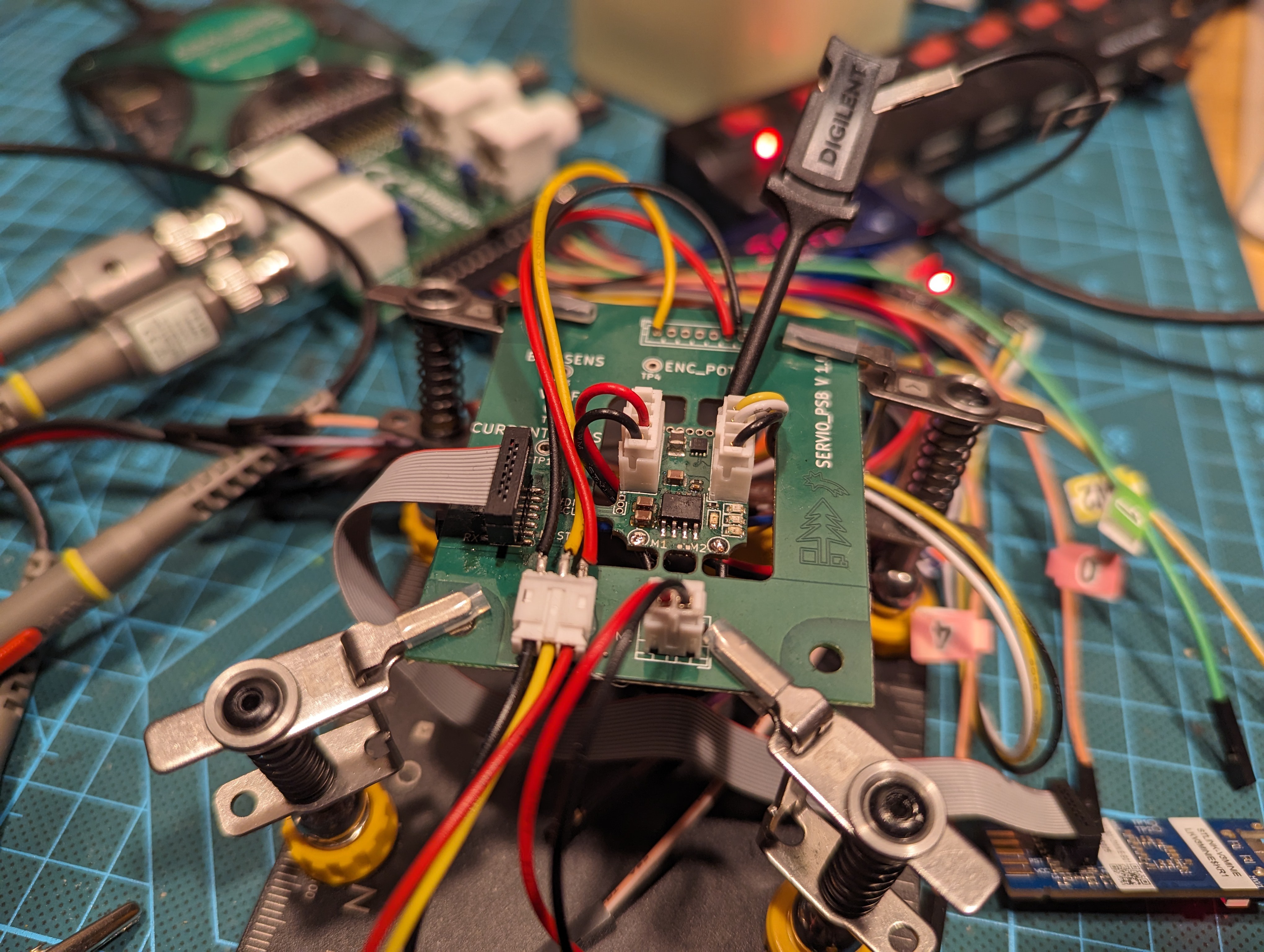
![]()
What is this all about? The crucial functionality of the servo is its ability to sense the current flowing through the motor. If this feature has bugs or doesn't work perfectly, none of the control loops will function properly either. Most importantly, it would be difficult to determine that the issue lies with the current sensing and not with something else. (Trust me, I learned this the hard way with previous prototypes.)
To visualize this:
![]()
Situation
The first step is to summarize what we are working with. Here's the simplified circuit:
![]()
Our H-bridge, DRV8251A, has current-sensing capability, as documented here. What happens is that based on the current flowing through the bridge, current flows from |PROP| to GND. This is what is measured by the MCU STM32H5 for current sensing. We use a 1k resistor R7 as a shunt resistor.
Tom V. also recommended using a 10n capacitor C15 to handle noise. Frankly, this was a bit troublesome for my CS-focused brain, which has a complete lack of EE knowledge. The question is:
Let's say you sense a current from a PWM pulse, how will the capacitor affect the values read by ADC relative to it being absent?
(Yes, this should be easy to answer for any EE graduate, but here we are.)
Math
The current from PROP is linearly scaled with a known fixed ratio: 1575 µA/A
Given that, we can formulate the basic formula:
V_R7 = I_R7 * R_R7
I_R7 = I * COEFF
What we want to know is: given some fixed voltage `V` measured on `R7`, what is the current flowing through the motor?
The answer to that is in the formula: `V_R7 = I * COEFF * R_R7`
Which, once we fill in the known information, gets simplified to: `V_R7 = I * 1.575`
Note that the resistor has quite a resistance for a shunt resistor, but given the drastic ratio between the real current and the current flowing through |PROP|, the values cancel each other out.
Baseline
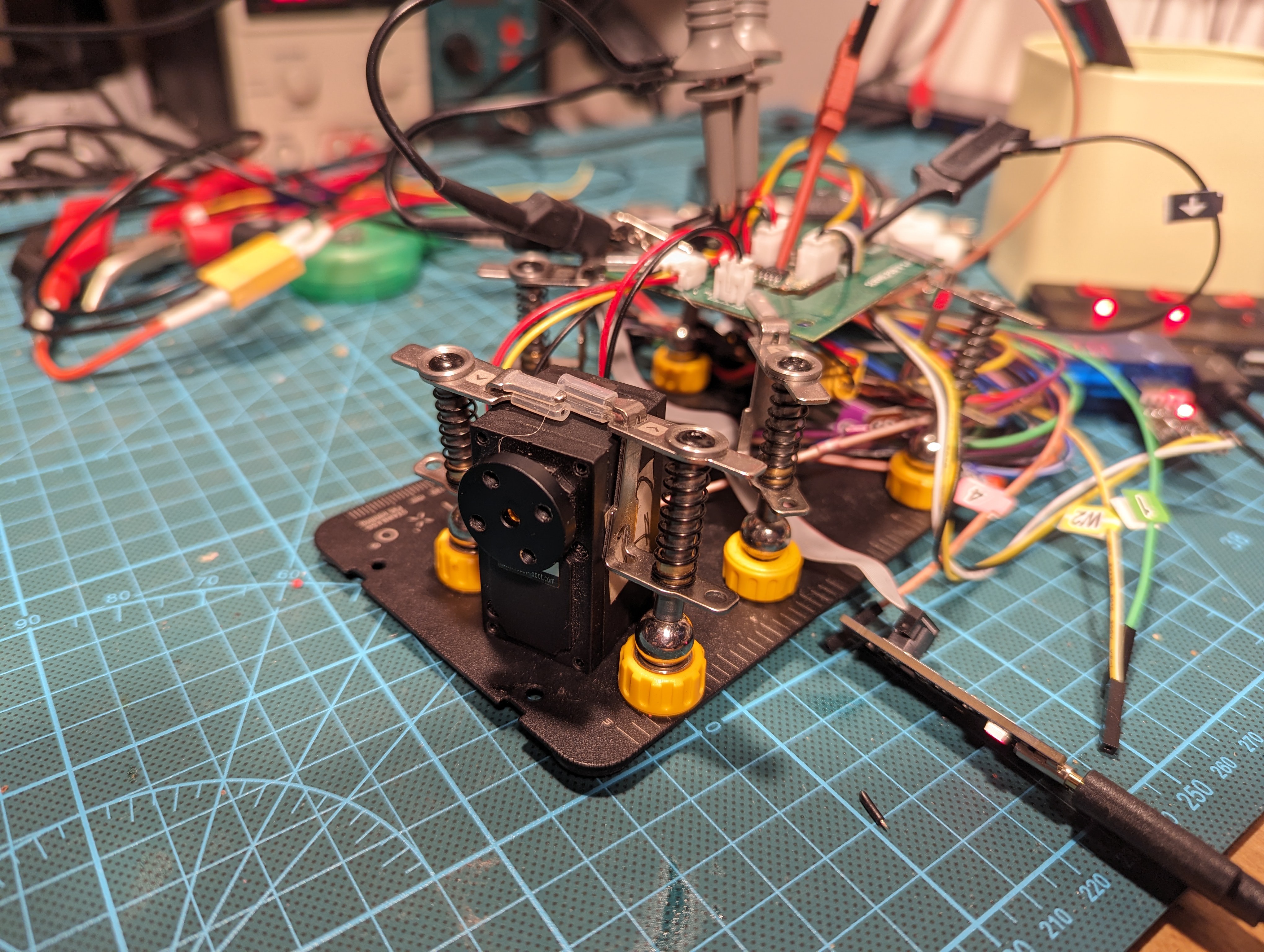
Given that we know this, let's take a scope and measure some things. What we can do is attach a motor to the servo, flash the production firmware, and use a control utility to set the servo to a fixed PWM duty cycle.
The motor is a scrapped Lewansoul LX15D. Since the motor was without any load, the expected current values should be low, as without resistance it won’t need much.
My trusted laboratory power source is powering all of this. The power source has the capability to measure current, so I relied on that for comparison values.
There are multiple scenarios during which I've taken data. In all cases, I relied on the Analog Discovery 2 for the measurements, as that device is my daily tool for such tasks. As you can see, I can even make fancy screenshots of the view from it :)
![]()
50% duty cycle on AD2 The interesting data is on Channel 2, which was attached to the current sense pin—effectively connected to the PA4 pin of the STM32H5 on the circuit above. I also made sure that I could observe the PWM duty cycle on the logic analyzer of the AD2; you can see it in the bottom row. (14kHz PWM frequency is about right)
Channel 2 gives us the voltage across the R7 resistor. I've also added a virtual channel,`Math 1`, that converts the values from Ch2 into the actual current flowing through the motor.
It should be noted that the current reported by the power source includes the power drained by the MCU and other peripherals, not just the motor, and at this point, there is no way for me to separate them. However, it should be manageable.
After all that was done and prepared, I measured relevant values for multiple scenarios. Note that I always used the `average` value for each channel:
power 0% 25% 50% 75% 100% power source current 11 mA 31 mA 57mA 81mA 106mA R7 voltage 18 mV 50 mV 155mV 177mV 224mV calculated motor current 12 mA 32 mA 98mA 112mA 142mA What do the measured values mean? I have no conclusions yet, and frankly, I would prefer to consult this with someone more skilled in EE to ensure that I'm not missing something. The interesting observations are:
- I have no clue how well my power source or the AD2 is calibrated.
- The MCU and other non-motor-related components might be consuming around 11mA, which seems reasonable.
- The voltage on R7 is increasing at a faster rate than expected—the current at 25% is identical, but at 100%, it is 106mA versus 142mA. This might suggest that the current-scaling constant for the H-bridge differs significantly, but that is not entirely unexpected. But, what if the capacitor in the circuit is causing some issues?
- For some reason, the voltage on R7 when the power is at 0 is non-zero.
Out of all of this, only point 4 is troubling me, as it might disturb the control loops more than I would want.
Time to bother my friends and ask them some questions!
More photos
![]()
Handy power source used during measurements ![]()
LX15D Installed next to current servio prototype -
Servio Overview (Part 5/5) - Control
03/16/2024 at 22:57 • 0 commentsFrom an algorithmic perspective, at its core, the main task of a servomotor is to take the desired control variable (e.g., position) and command the connected DC motor in such a way that the desired position is achieved.
For Servio, we aimed for somewhat advanced forms of motion planning and control. In the first milestone, we chose basic control loops for three variables: current, position, and velocity.
We implemented three modes for Servio, in which the firmware focuses on controlling the respective variable - current mode, position mode, and velocity mode. In each mode, multiple control loops can be active:
- Current mode - uses just the current control loop.
- Position mode - uses both the current control loop and the position control loop.
- Velocity mode - uses both the current control loop and the velocity control loop.
To make the loops work, we introduced a Kalman filter into the system to estimate the current velocity/position based on the sensor used for the axis angle. This was necessary as we needed some way to estimate the velocity accurately.
All of this is illustrated in the following diagram:
![]()
Current control loop
The main control loop, the only one in direct contact with the hardware, takes a desired current as an input and controls the power sent to the motor based on the currently sensed current.
It operates as a standard PI control loop, using current as the input values to produce the desired power for the motor. The power is represented by a value ranging from -100% to 100%. (The current loop is not aware that PWM is used.) This output is then fed into timers, which generate PWM pulses to the H-bridge used by Servio.
Based on some insights from the industry, we decided to use a PI controller at 10kHz, as we were informed that the key to making the control work correctly lies in the frequency. That is, a high-frequency PID will be more tolerant to PID coefficient tuning.
To achieve this, we generate PWM at a 20kHz frequency. Each control loop iteration spans two PWM periods:
- Odd cycle - We sample the current flowing through the H-bridge. In the diagram, the sampled values are represented by blue dots. In the real system, we can sample up to 30 values.
- Even cycle - The average of these values is calculated, and this average is given to the control loop, and a new PWM value is calculated.
![]()
Current sensing scheme Note that the exact frequencies of the control loop and the PWM are not fixed; we have just fixed the ratio between them. In the future, we want to experiment with changing the frequency, ideally to try a higher value. In the control loops schema below, you can see which parts of the system are active in control mode.
![]()
Position control loop
We sense the position from a potentiometer at a frequency higher than 1kHz, which governs the frequency of the position control loop. This loop uses a PID controller that takes the measured position and the goal position as inputs and calculates the desired current flow through the system. Thus, the position control serves as an input to our current control loop, which handles the rest.
We don't use the measured position directly; instead, we rely on a Kalman filter to perform some filtering on the measured value.
Given the high static friction in our test system, there were issues with the robustness of the loop. To address this, we decided to implement an extra bias. If the servomotor is not moving, the current output from the position control loop is multiplied by a scale value (2.0). This scale value linearly degrades once the servo starts moving and reappears linearly once the servo stops. While not a perfect solution, it has proven to be good enough as it is quite intuitive to configure. (This bias is not visible in the schema.)
In the schema below, you can see which parts of the system are active in position mode.
![]()
Velocity control loop
Velocity control operates on the same principle as position control; we use position readings to estimate velocity. We employ a PID regulator that takes the actual velocity and the desired velocity as inputs and outputs the desired current to achieve the given velocity.
The challenging part was the estimation of velocity, which is why we introduced a Kalman filter into the system for processing the position readings. We configured the filter to take position as an input and output estimates of both position and velocity. The velocity estimate from the Kalman filter is what we use for velocity control. So far, it seems to be good enough and stable, although we have not yet conducted satisfactory tests for it.
This also proved to be a challenge a bit, as it required some time to modify the filter appropriately to work with continuous values, such as the angle of rotation.
In the schema below, you can see which parts of the system are active in velocity mode.
![]()
Limits
What consistently emerged as a challenge were the limits. I had a strict requirement that the configuration options for the servo should include limits for maximum and minimum position, velocity, and current. This means that users should be able to set restrictions on all these parameters, and the servo should adhere to them under all conditions. We considered these to be soft limitations - exceeding the range is not viewed as an error, but rather something that needs to be rectified.
Ensuring adherence to current limits while in current control mode is straightforward, and the same is true for other variables within their respective control modes. It is also simple to maintain awareness of current limits during position or velocity modes, as both use the current control loop, thus honoring the current limits.
The challenging part is: How do we ensure adherence to position and velocity limits in a the current mode that only activates the current loop? How can we maintain position limits in velocity mode? And how do we maintain velocity limits in position mode?
![]()
We devised a solution that adjusts the current limits based on the current position relative to the position limits. This concept is illustrated in the figure above. The red line symbolizes the current limit for the servo; as the position (`pos`) approaches the maximum position limit (`max`), the current limit decreases. When `pos` reaches the `max` value, the maximum current limit will be `0 A`.
The implication of this approach is that the servo will not be able to generate maximum current when nearing the position limits, but this was considered an acceptable compromise.
-
Servio Overview (Part 4/5) - Continuous Integration
02/16/2024 at 21:38 • 0 commentsWe can think of Continuous Integration (CI) in two ways: as an approach to development and as infrastructure. For Servio, both aspects are relevant, as we heavily utilize CI for development.
As a development approach, the philosophy centers on continuously testing new changes to ensure they do not disrupt the system as a whole. This contrasts with making large changes and integrating them into the system sporadically to see if anything breaks. Essentially, it emphasizes incremental updates.
![]()
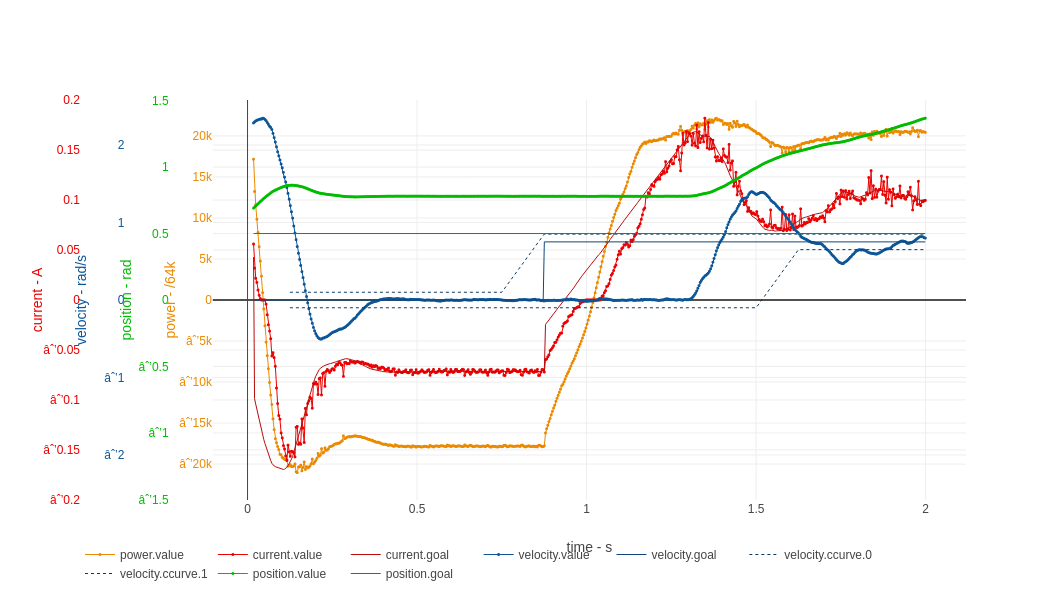
Ater we re-factored code for static-friction compensation, we run step velocity test... to find out immediatly that the refactoring has some issues. (Executed on real hardware) From a coding perspective, we often use a powered test jig on the desk and periodically run the full test suite with it. This practice helps us identify any errors or issues introduced by changes—sometimes these are bugs, and sometimes they are expected outcomes.
![]()
Technically, we hide the testjig in a shelf in some cases, so it's not on the table Another perspective involves the backend connected to the server. Once any change is committed and merged into the main git repository, the same testing process automatically occurs in the background for each commit.
![]()
Screenshot of HTML report produced by GitHub runner. emlabcpp and joque
Regarding the library subprojects, emlabcpp and joque, each has its own CI setup and pipelines.
From Servio's perspective, these libraries should be tested through their own mechanisms without any explicit testing on Servio's part.
Docker container
Regarding Docker containers, we opted for an automated build and testing environment by creating a Docker image based on the official Arch Linux distribution. We simply add our build tools and dependencies to this image and use it across all our pipelines for repositories. This image is publicly available, and we encourage its use. Dockerfile is here.
Public repo
Our public repository builds everything in CI and runs unit tests to ensure the build is independent of any specific details of the developers' environment. The unit tests check basic functionality, but due to their limited coverage, more comprehensive testing is conducted in the private repository.Private repo
For the private repository, we have a GitHub runner for pipelines, equipped with a smaller version of the test jig with a Servio PCB permanently connected. Currently, this test jig is unpowered and disconnected, as leaving a power source permanently enabled presents a risk. This setup resides in my living room, and I have yet to decide to leave any power source permanently on for an automatically starting device.
![]()
PCB For GitHub runner - Is it just a PCB laying on shelf somewhere close to USB hub? yes! For each commit in the private repository, we initiate a build of all firmware and tests on our runner and execute a full suite of tests. The test suite can be adjusted for an unpowered scenario, affecting many tests, some skip themselves, while others simply disable evaluation.
-
Servio Overview (Part 3/5) - Hardware
01/28/2024 at 21:01 • 0 commentsHardware
Relative to software, the hardware might be underdeveloped. This could be because the project is intentionally more focused on software. Importantly, from a hardware perspective, the Servio project only includes PCB designs, without any casing or mechanical designs. The general idea is that the casing, metal gears, DC motor, or potentiometer must be provided by the user. Servio essentially comprises just the PCB with its software.
For the project's development, we have so far created three iterations of the PCB and have a test jig in an unfinished state.
General PCB Requirements
Generally, the requirements for Servio PCBs are straightforward: The PCB needs a compatible MCU and an H-bridge to control the motor. It would also be practical to include connections for a rotation sensor (at a minimum, a potentiometer), a power source to regulate voltage for components, LEDs for indication, and some connectors.
We intentionally practice minimalism in this way to ensure that designing a new PCB is as simple as possible, which allows for high flexibility in PCB design.
Prototype v1
The first iteration was designed with the following goals:
- Make it easy for debugging (hence its large size, we made it fit within 10x10cm).
- Experiment with various components (we included extra SPI encoders and used WS2812 LEDs because we initially thought they were necessary).
- Integrate the STLINK V3-mini.
- Use the STM32G431KC - 170 MHz, 128KB of FLASH, 32KB of RAM.
We began development with this board and conducted most of the development on it. The only major issue was with the H-bridge, which led yaqwsx to hand-solder an alternative H-bridge to circumvent the limitation.
There was some debate about the kind of MCU we needed; we intentionally chose a more powerful one than we thought necessary. Why? To reduce development time by minimizing the need for performance optimizations.

First version of development board Prototype v2
The second iteration was intentionally made smaller, mostly at my request, so I could more easily integrate it into actual applications. The board was designed as two connected PCBs: one being the servo itself and the other a debug board.
The goals here were to:
- Use the STM32G431KC - it works just fine and we actually use the computing power.
- Use the DRV8870DDA as the H-bridge.
- Switch from WS2812 to standard LEDs.
- Rely on the STLINK-V3 mini.
Essentially, the second iteration intentionally narrowed the scope, and made stuff smaller.
![]()
A bunch of prototype v2 boards waiting for usage, you can see the v1 below it. ![]()
v2 devel board in first iteration of testjig, we used standard 40x20x20mm servo Prototype v2 - Test Jig
With the second iteration of the development board, I put more effort into a test jig - a test harness that could be used for any development done by me or for further development automation.
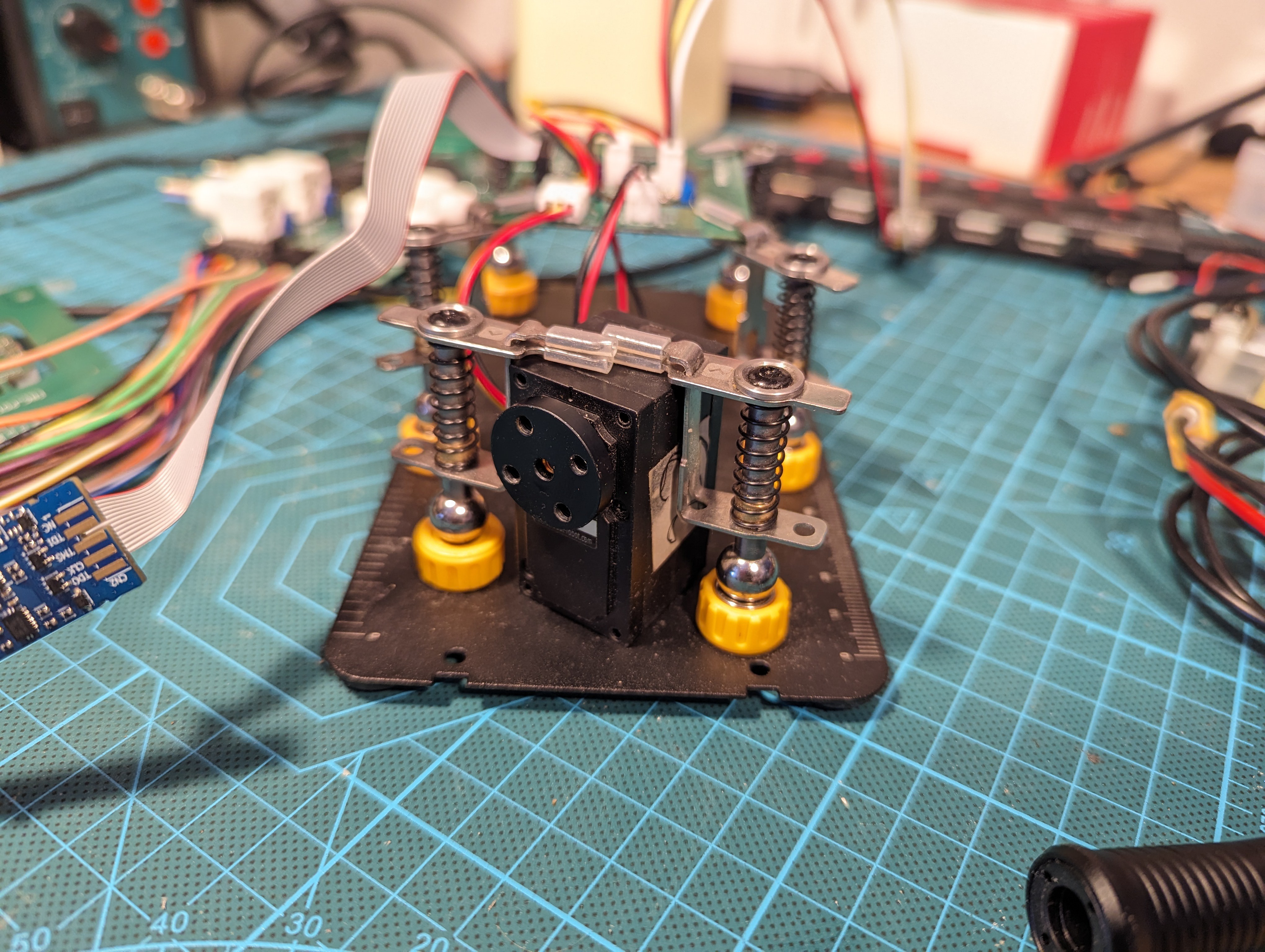
The test jig contains a DC servomotor without a connected PCB to an external Servio PCB (v2) in a DIY-made box. There are other external boards that allow the addition of more sensors around the actual servo, such as an encoder directly connected to the servo shaft. During development, the servo was powered by a standard laboratory power source.
Key takeaways from this experience:
- The test jig was quite beneficial to development.
- There may be a need for various types of test jigs.
- The extra-sensory part of the test jig was unfinished, and there was no immediate motivation to complete it.
All in all, this part of the project will definitely have its own detailed log in the future.
![]()
The base of testjig is fairly sized box made out of totemmaker ![]()
The testjig contains v2 board, servo mounted on stand with encoder, usb hub with external UART, and another STM32H7 for potential extra stuff Prototype v3
Generally, v2 was almost adequate, but we wanted to add some final touches to the board and decided to create v3, with goals to:
- Make it as small as reasonably possible - small enough for production use.
- Switch to the STM32H503 (practical reasons: a more readily available chip at a lower price, with higher computing power as a nice bonus).
- Switch to the DRV8251ADDAR as the H-bridge.
Apart from these different goals, we also changed the PCB designer; this time, the PCB was designed by Tomas Vavrinec. He kindly offered his services, as yaqwsx simply ran out of free time.
We just got the boards fresh out of factory!
![]()