 Bill Collis
DIY UPS for Home Assistant Green & Xfinity XB7 Modem
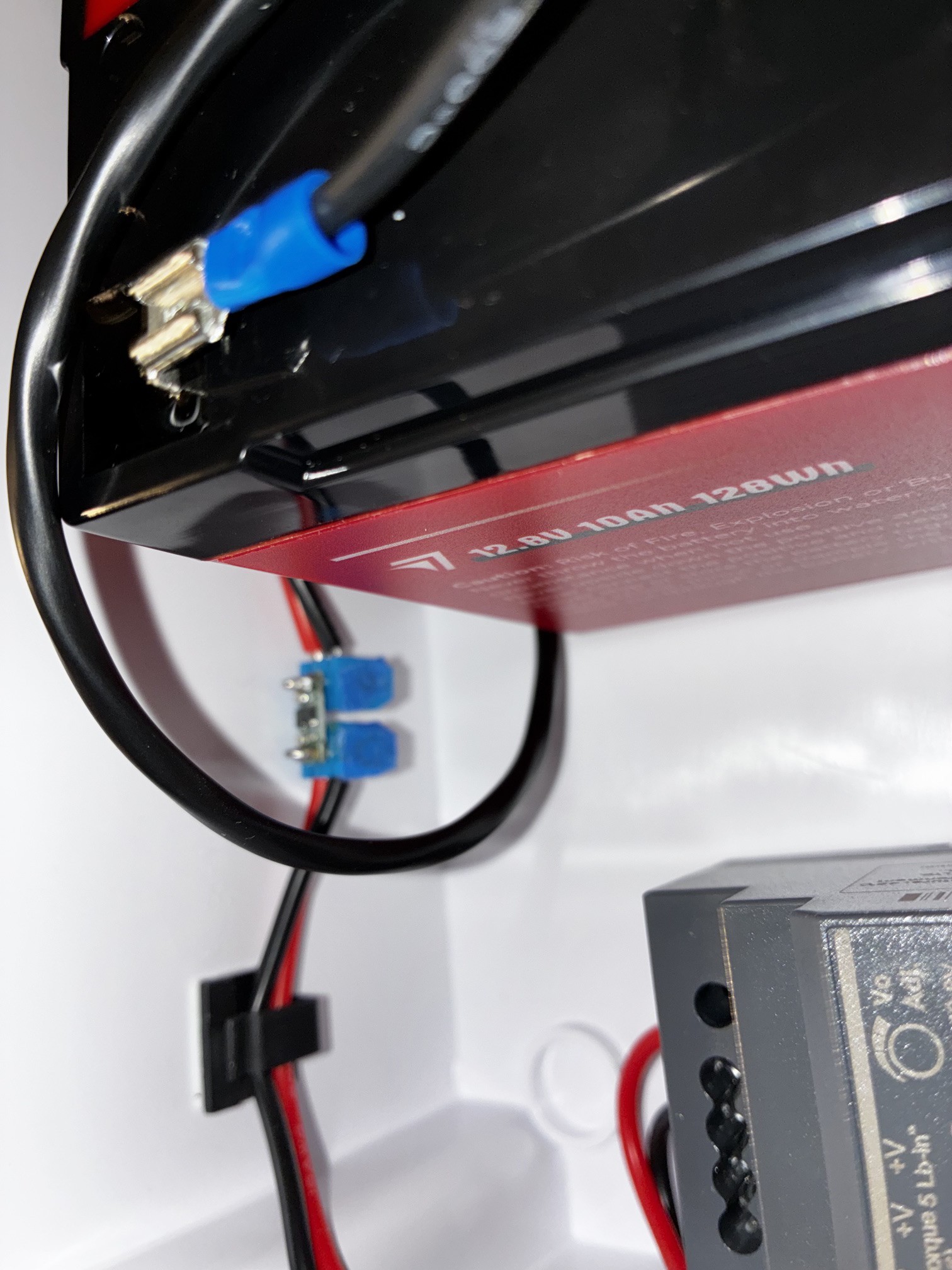
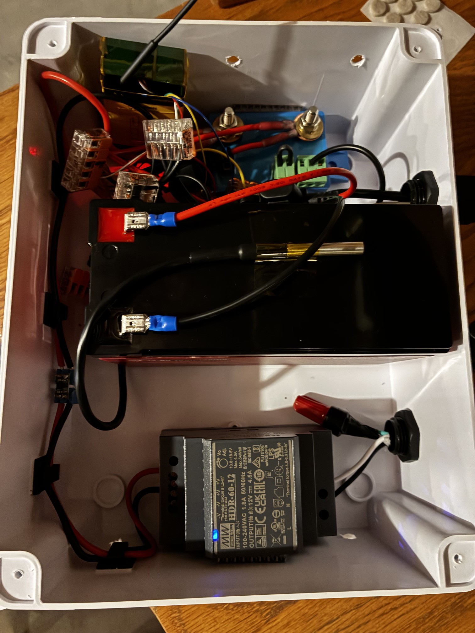
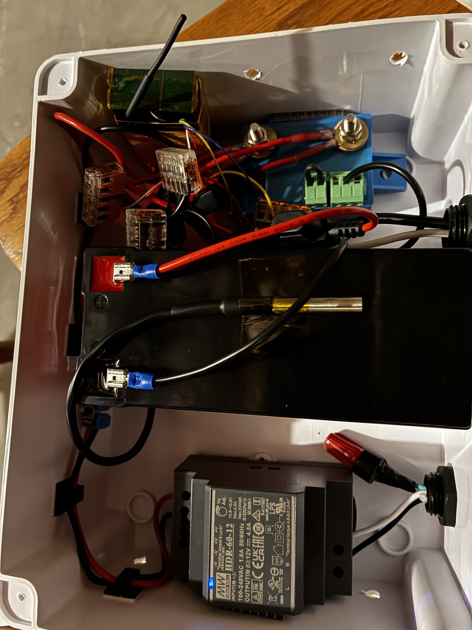
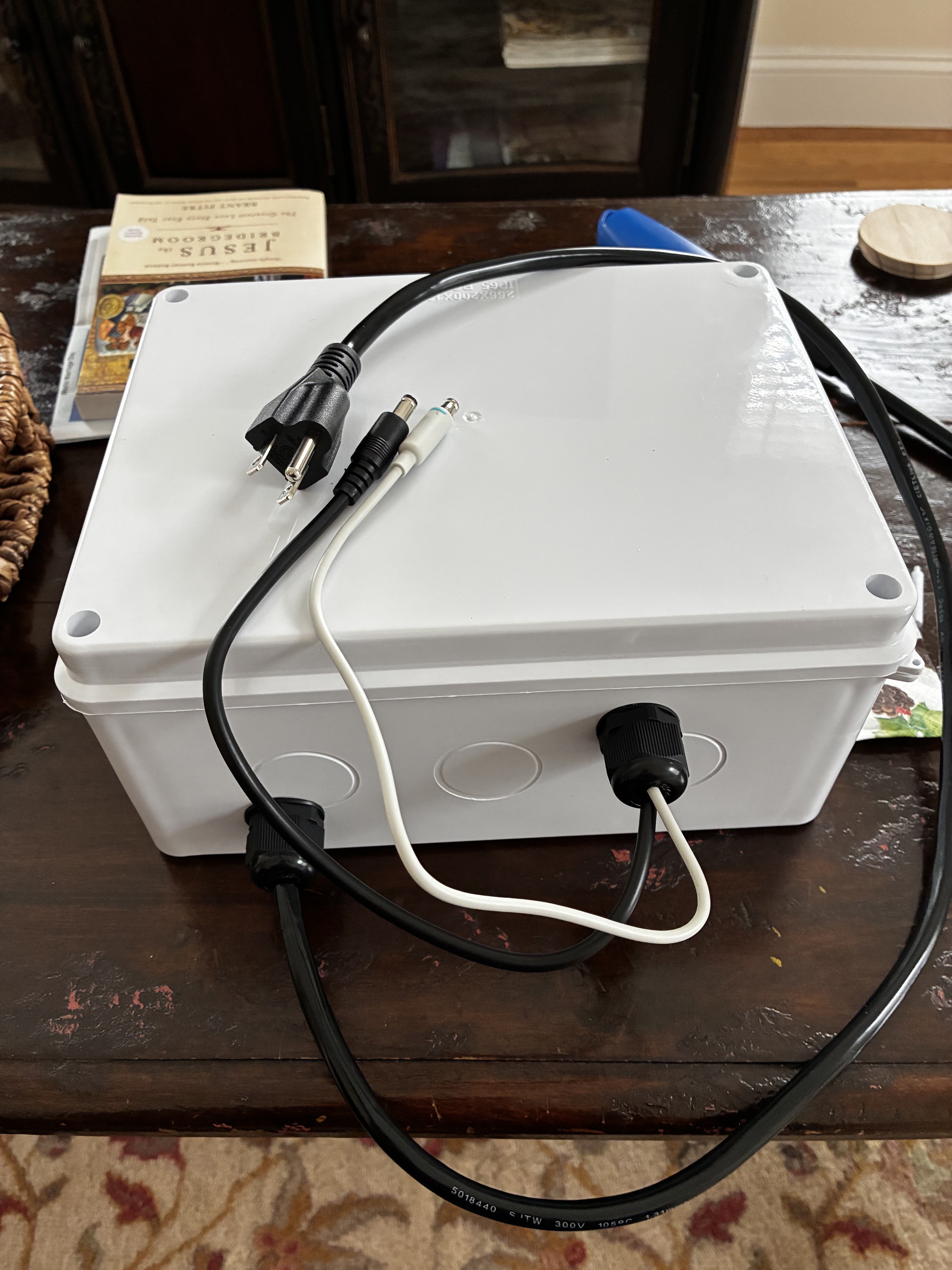
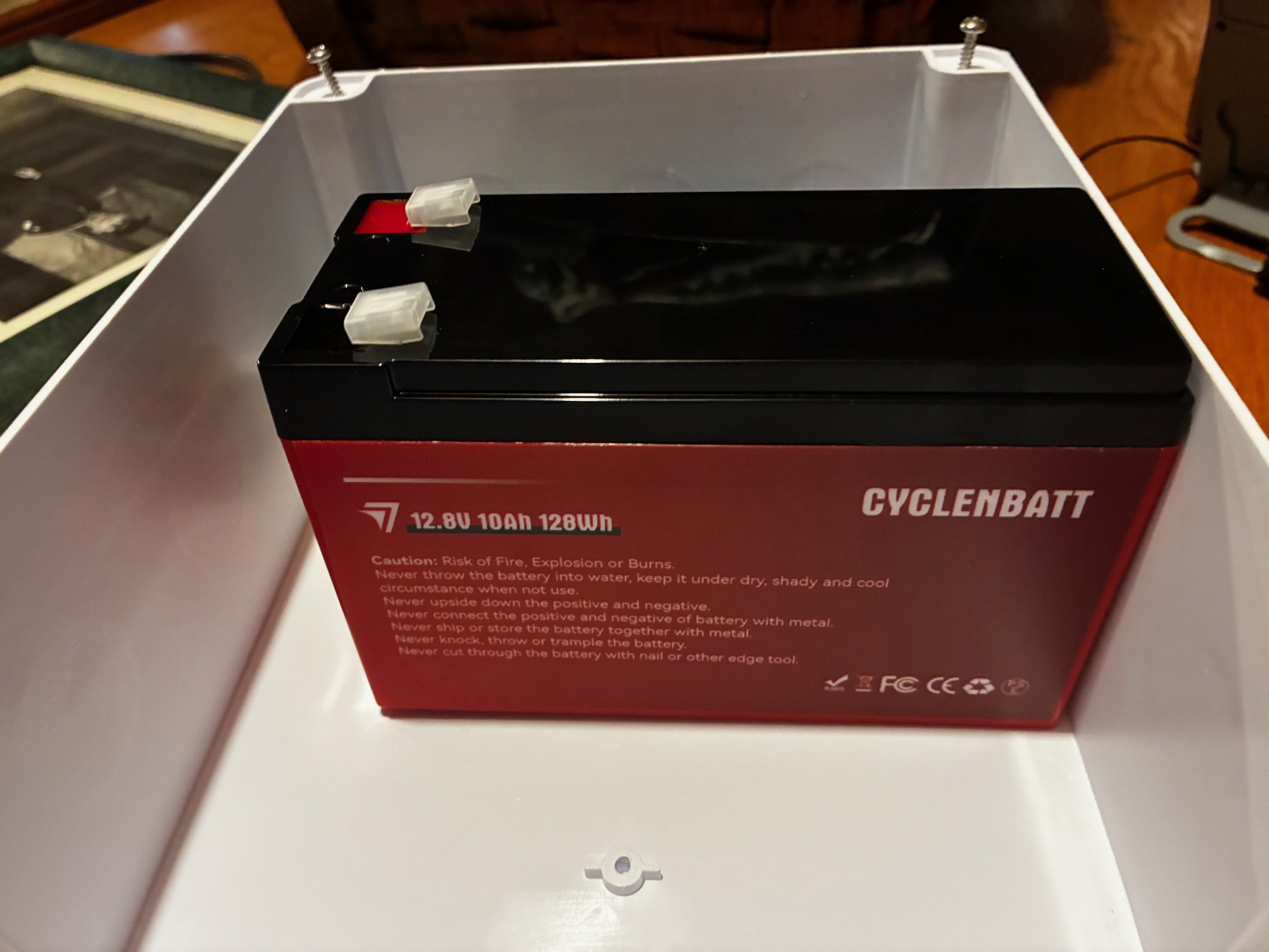
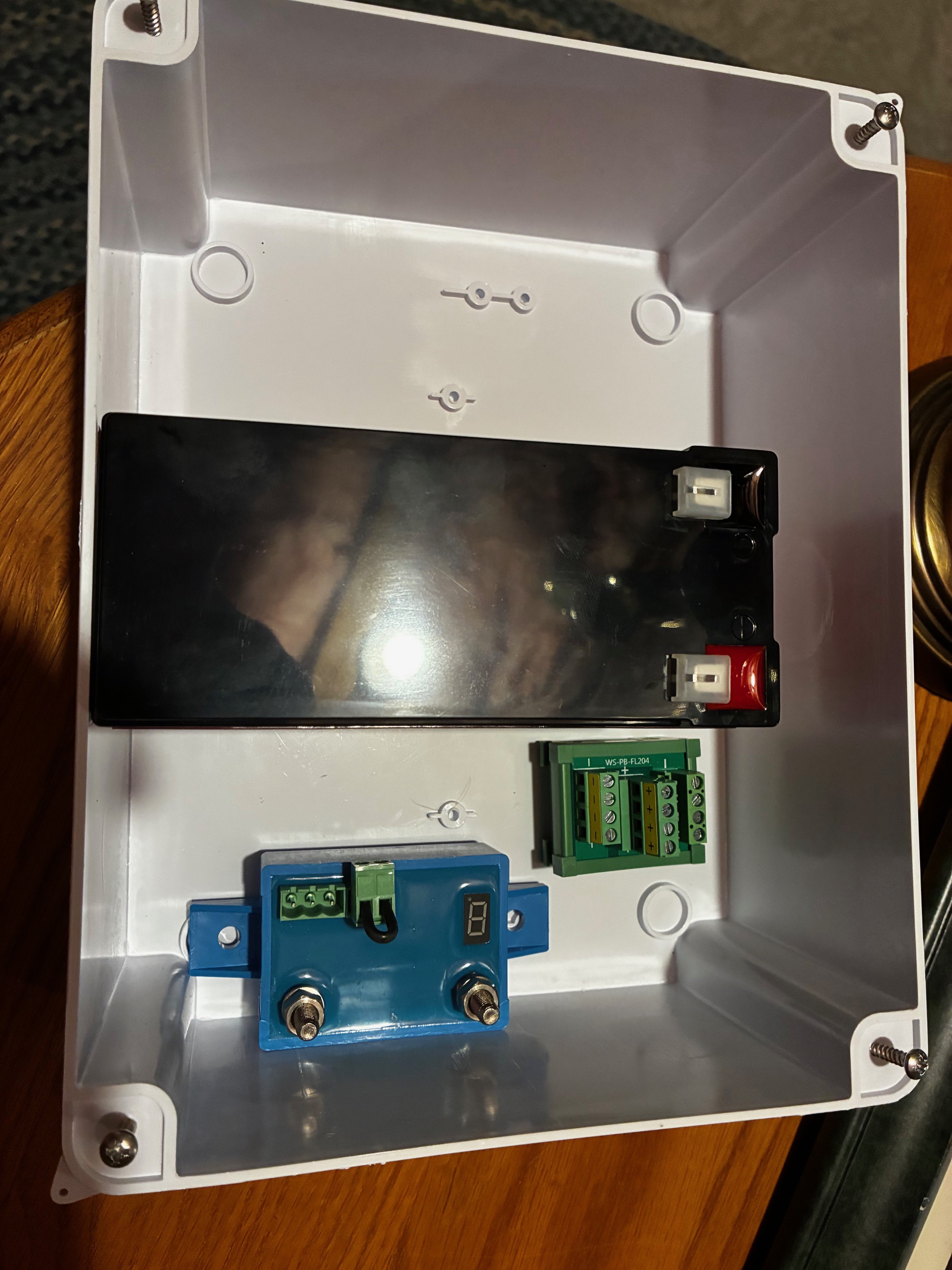
A 12V LiFePO4-based uninterruptible power supply for keeping a Home Assistant Green and Xfinity XB7 cable modem running during grid outages. Built into an IP65 enclosure with Home Assistant monitoring via Shelly Plus Uni.
Honest context: A $85 APC BE600M1 provides comparable backup capability. This build costs roughly the same over 10 years as that option (based on battery replacements and electricity usage). The engineering rationale — longer battery life, faster switchover, direct HA integration, no DC-DC converter voltage regulation — is documented in design-rationale.md. Build this if those tradeoffs matter to you.
Performance
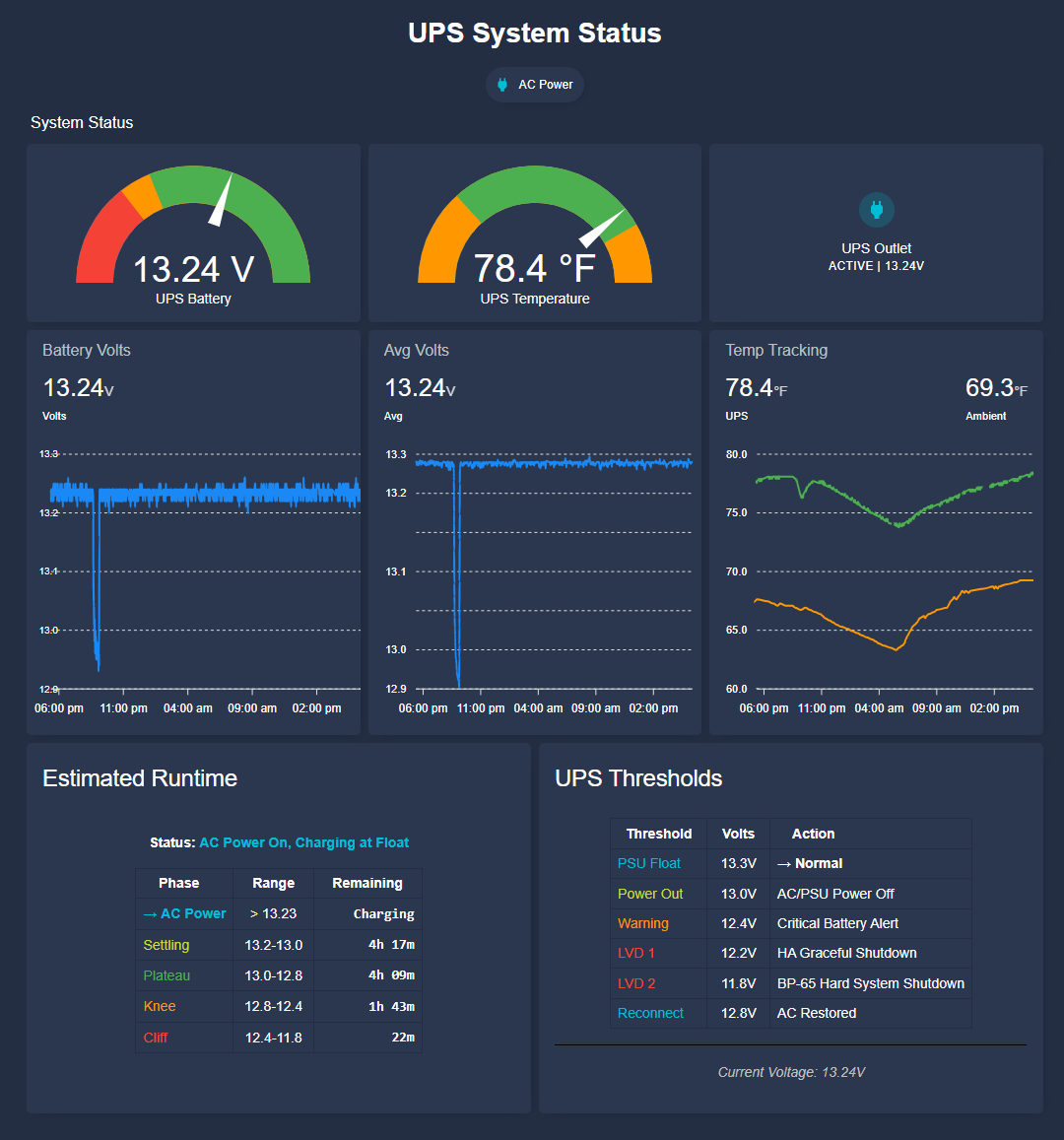
Summary Validated Runtime: 4.25 hours to software shutdown (12.2V) and ~4.3 hours to hardware LVD (11.8V) under a sustained 14.5W load.
Key Finding
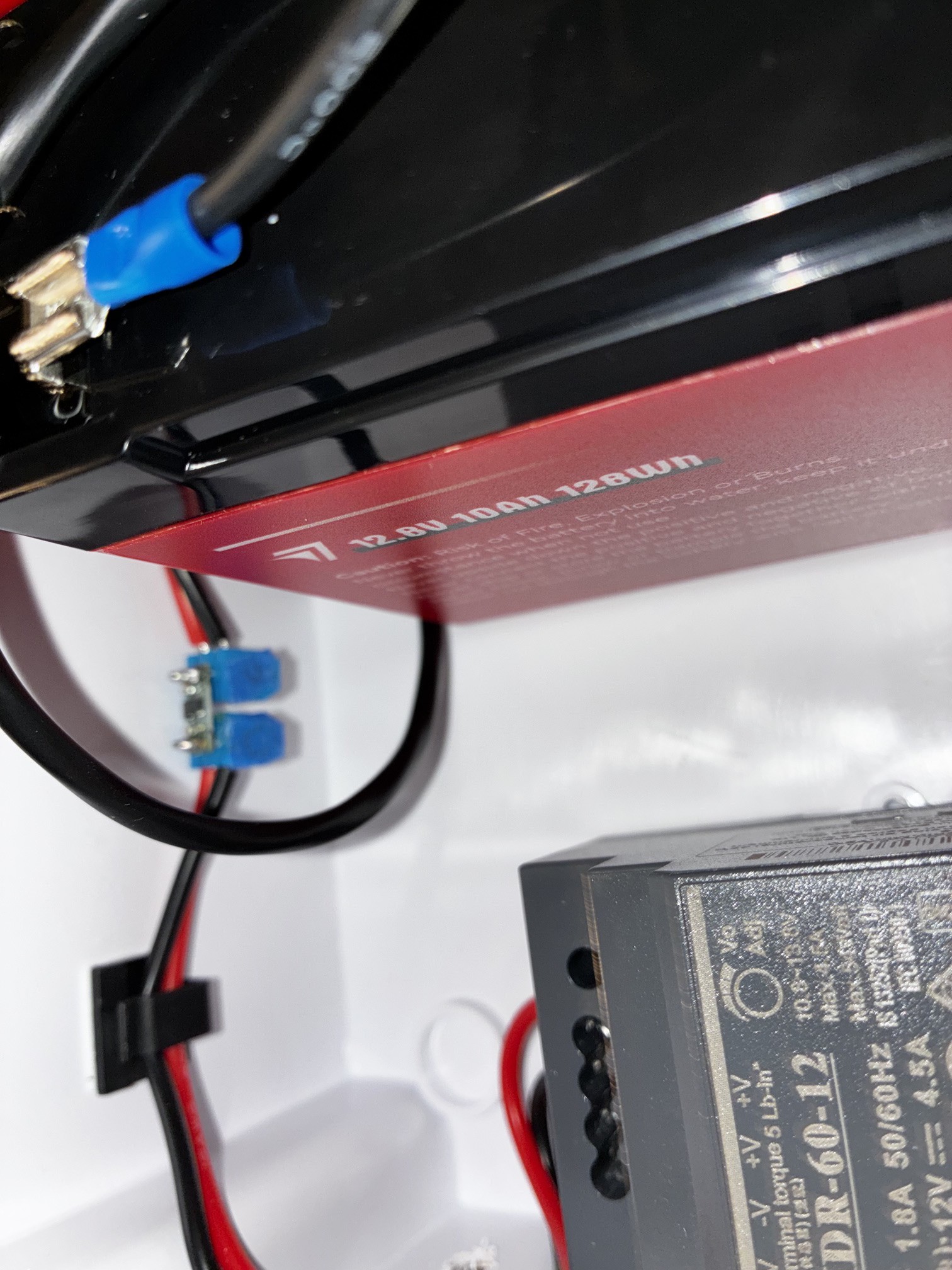
The UPS delivers a reliable ~4.3 hours of runtime at typical Xfinity XB7 Modem and HA Green loads (~15w). This is ~55% of the theoretical maximum capacity of the 10Ah LiFePO4 battery. This result is not due to battery degradation, measurement error, or software issues. It is a direct consequence of the single-rail 13.3V CV architecture.
Why the Runtime is Limited
The system uses a single shared rail for both charging and load. To keep the voltage safe for the connected equipment, charging is capped at 13.3V. This restricts the battery to approximately 65–75% SOC and prevents proper absorption charging at 14.4V. As a result, the top ~25–35% of the battery’s rated capacity is never accessible.
Discharge Characteristics
Extremely flat voltage plateau from 13.0V down to 12.8V (delivers the majority of usable energy)
Sharp “cliff” begins at ~12.45V, after which voltage drops rapidly
12.4V warning provides an effective “immediate action” alert (~5–6 minutes before shutdown)
Conclusion
The system performs exactly as designed. The layered protection (voltage warnings → automated shutdown → BP-65 hardware LVD) is robust and safe.
Current validated specification: ~4.3 hours runtime at 14.5W under the existing single-rail topology.
A two-stage charging architecture (dedicated 14.4V charger + DC-DC regulator) would be required to approach the full ~7.8–8.5 hour theoretical runtime.
Complete Report and Data can be found at: https://github.com/wkcollis1-eng/DIY-LiFePO4-UPS/blob/main/docs/UPS_Validation_Report.md
Last validated: March 2026 (Test D3)
UPS Integration into Home Assistant
HA Integration details can be found at: https://github.com/wkcollis1-eng/DIY-LiFePO4-UPS/blob/main/HA%20Automation/README_HA_UPS_Integration.md
Commissioning Results
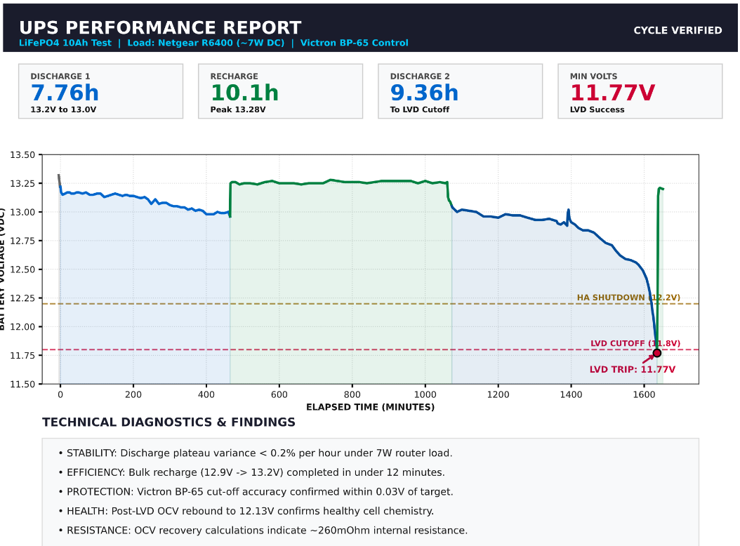
The chart records a full two-cycle discharge test performed March 25–26, 2026 using a Netgear R6400 router (~7W DC) as a substitute load, with battery voltage logged via the Shelly Plus Uni at 5-second intervals. Discharge 1 (7.76h): Voltage held the characteristic LiFePO4 flat plateau from 13.2V to 13.0V over 7.76 hours — a drop of only 0.2V at light load, confirming textbook cell behavior. Recharge (10.1h): AC restored; PSU returned the battery to float within minutes, peaking at 13.28V and holding stable through a 10-hour recharge window. Discharge 2 (9.36h): A second full discharge ran the battery to LVD cutoff. The Victron BP-65 tripped at 11.77V — within 0.03V of the 11.8V design target — confirming protection circuit accuracy. Post-LVD OCV rebound to 12.13V confirms healthy cell chemistry with no permanent capacity loss from the deep discharge.
Key findings:
-Discharge plateau variance under 0.2%/hr
-BP-65 cutoff accuracy ±0.03V
-Internal resistance ~260mΩ at low SoC (derived from OCV recovery)
-Bulk recharge from 12.9V to...
Read more »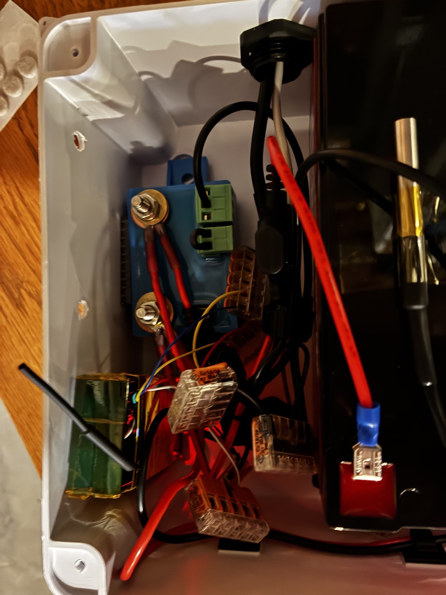


 Manuel Alfonso
 Sagar 001
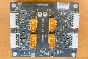
 Bud Bennett
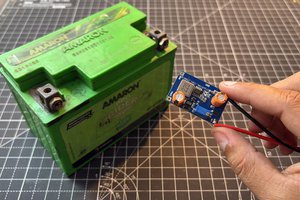
Hi Nicholas,
This is one of the nuances of the design -
Neither — this design bypasses CC-CV entirely by using passive float
charging.
How it works:
- PSU is set to 13.3V (LiFePO4 resting voltage)
- Current is naturally limited by the voltage differential between PSU and battery
- As battery charges, the differential shrinks → current tapers organically
- At equilibrium, current drops to near-zero (microamps)
The BMS role:
- The Cyclenbatt's built-in 10A BMS provides protection only (OVP, UVP, OCP, short circuit)
- It does not regulate charging current — it would only intervene if current exceeded 10A (which can't happen here since max PSU output is 8.5A, and typical charge current is <2A)
Why this works for LiFePO4:
- LiFePO4 has a flat discharge curve and tolerates indefinite float at 13.3V
- No risk of overcharge since 13.3V is below the 14.4-14.6V charge termination voltage
- Trade-off: charges to ~95% SoC rather than 100%, but extends cycle life
Hope that answers you question.
Bill