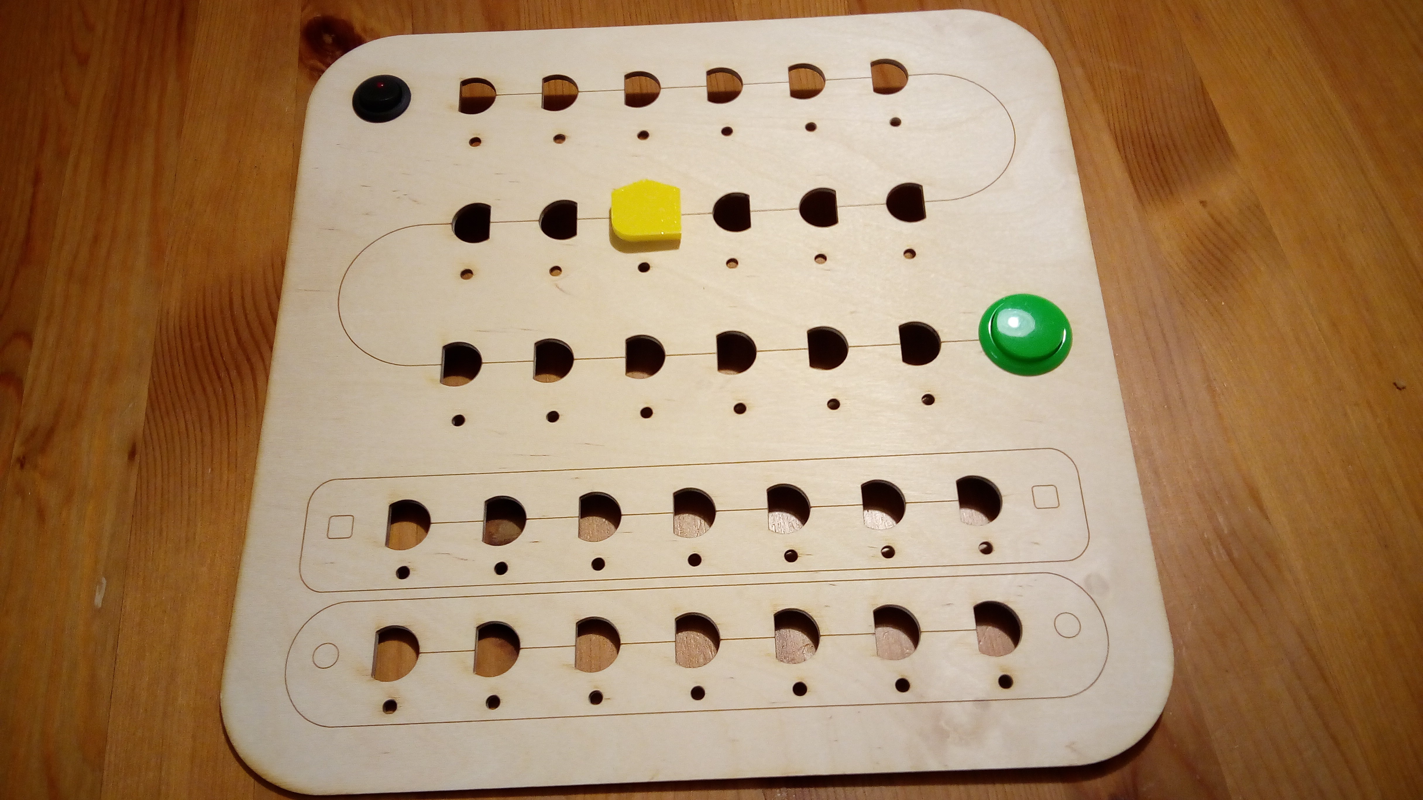
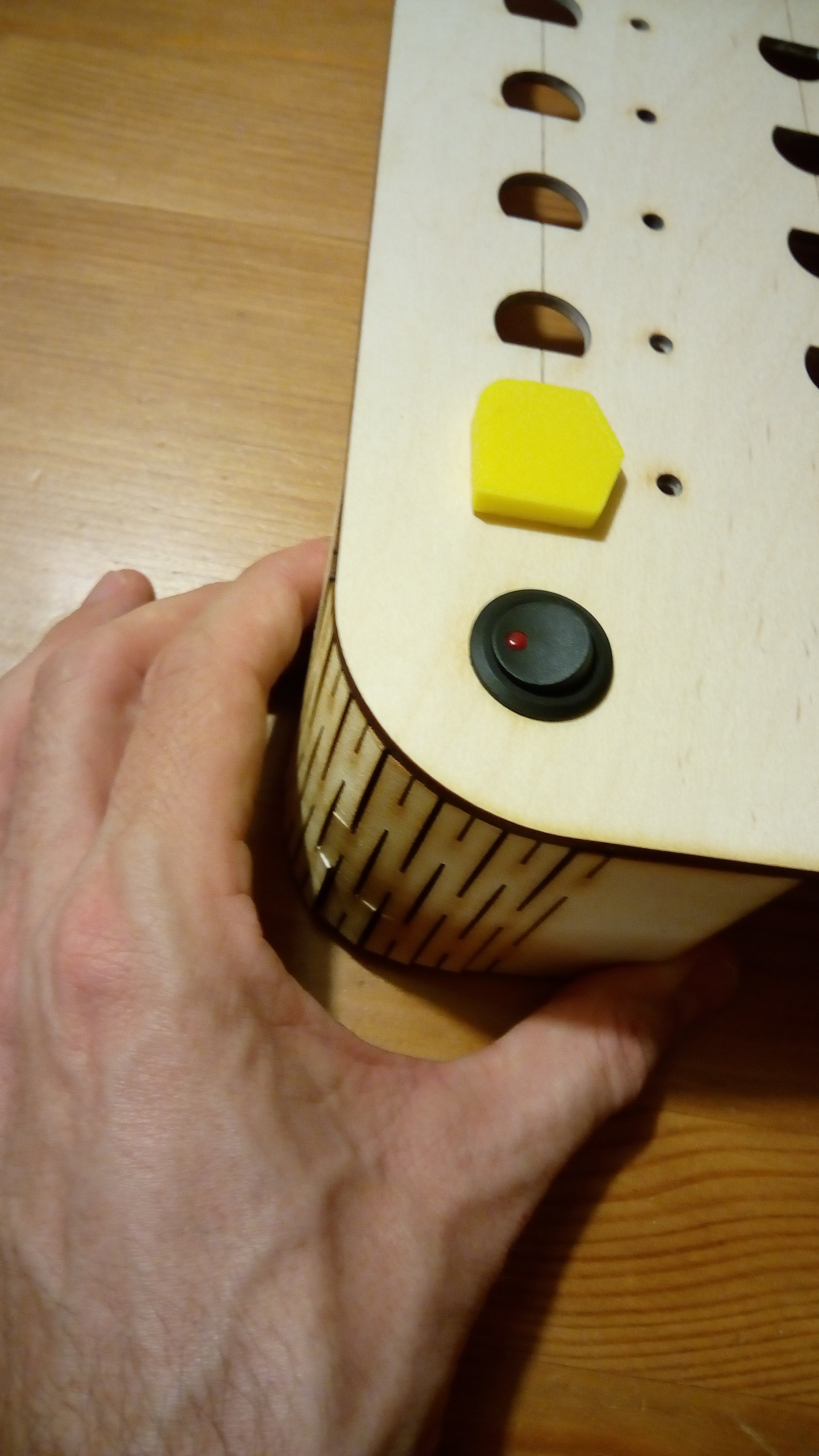
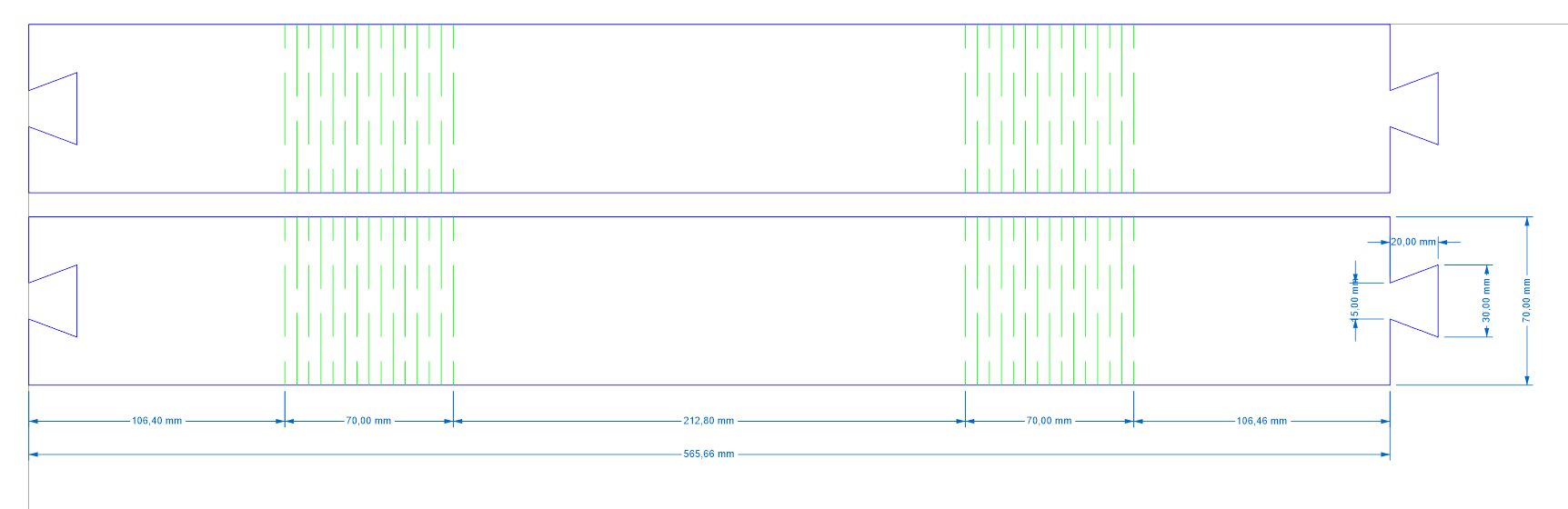
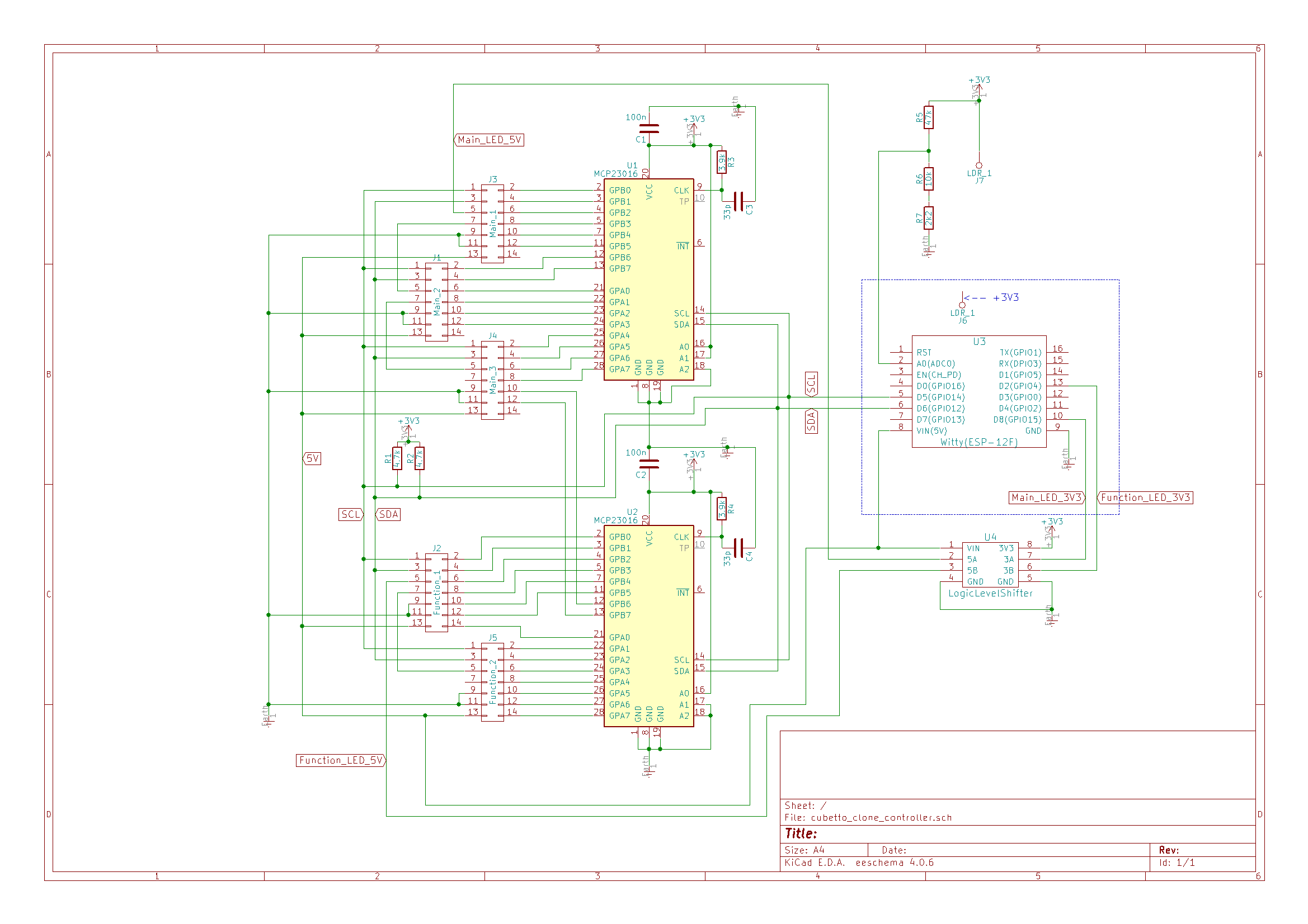
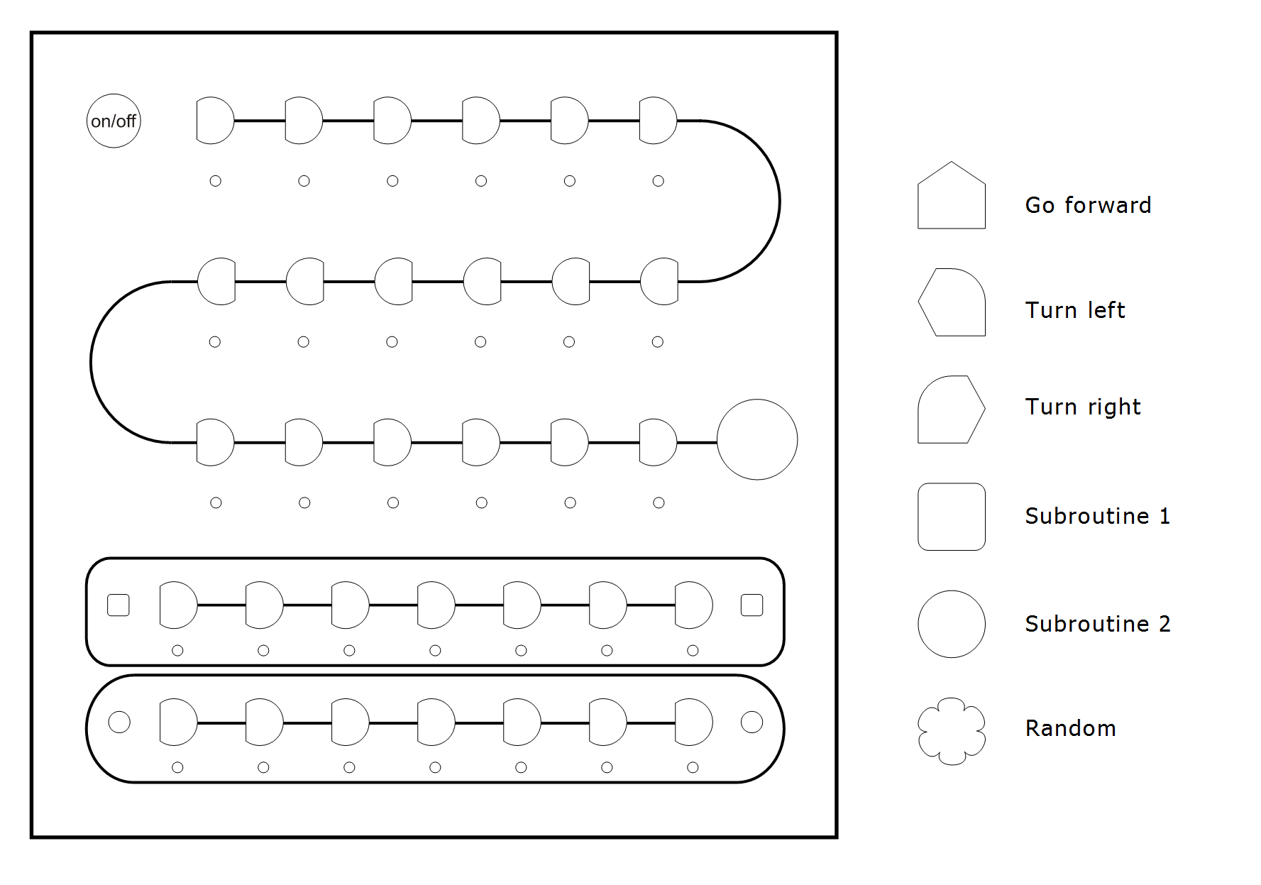
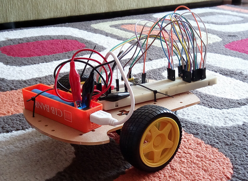
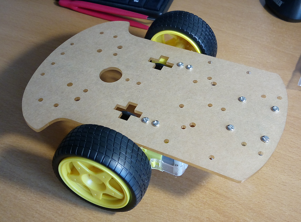
I would like to build a re-engineered Cubetto clone for my son.
To make the experience fit your profile, pick a username and tell us what interests you.
We found and based on your interests.
testdrive.avithe Q'N'D test drive of the carAudio Video Interleave (AVI) - 10.95 MB - 04/09/2017 at 09:53 |
|
|
testdrive.3gpthe Q'N'D test drive of the car3gpp - 25.54 MB - 04/08/2017 at 20:56 |
|
Few posts earlier, I wrote about the 28BYJ-48 steppers in transit from China. I got them earlier, and was testing them in the past few days. While driving one motor directly from ESP8266 pins made results in no time, for two motors it would need 8 pins. All that an ESP has. I wasn't comfortable with it, and thought about expanding the ports with MCP23017. Unfortunately all the stepper libraries works only with native pins, and that meant writing the stepping program from scratch. Fortunately it is not so complicated, so I have somewhat a working prototype.
At the moment, it looks good. But there is something weird. Having the I2C communication on 100kHz or 400kHz, does not influence the communication time. I am debuging it like this:
ptime = micros();
Wire.beginTransmission(MCP);
Wire.write(GPIOA);
Wire.write(B10101010);
Serial.println(Wire.endTransmission());
atm = micros();
Serial.println(atm - ptime);
This is giving me 350-400 microsec., no matter what I2C speed I use. I did find out how to speed it up, by raising CPU clock from 80MHz to 160MHz, but it gave me speedup of about 50us only. I find it too slow, I was hoping to have an I2C communication time in the domain of 100-150us. Searching around the 23017 datasheet, I came across the sequential and byte mode, and the address auto increment. I was trying to not close the I2C communication, but to make a restart with:
Wire.endTransmission(false)
But. If after the above, I issue a simple:
Wire.write(B10101010)
Wire.endTransmission(false)
I get no data transferred to MCP. No matter what, if there is no beginTransmission, write(address), write(data) and then endTransmission, I get no data transferred to MCP, and if I include all this, then the restart ('endTransmission(false)') does not matter for the run time.
Really it doesn't matter too much, this stepper is not too fast, there is enough time, but I am curious, so I want to find out. But at the moment, it is working nicely, the motors are spinning, and I am trying to make a chassis for them, to test their usability for driving the robot.
I count it success. The CNC cut plywood, sanded with 320 grit sandpaper (to remove traces of burning):
It looks nice. The living hinges are half success. Basically OK, but not enough lines. I have put them on 5mm from each other, and it looks like too much. I will try out the 3mm.
There are cracks, and I hope that with more lines it will bend fine. We'll see soon.
I had to add the corel draw to my list of new thing that I am learning for this project :) The FabLab's laser CNC are controlled from it, so that's decided. Here is a blueprint for the controller. Top:
Side:
I will try the flex (of living) hinges.
At the moment, the codes for the two ESP's are in an advanced condition. Thinking about communication between them, I came to the idea, to create a new protocol. Not a completely new thing, it still communicates over TCP/IP, but something to add to the bare byte transfer. Some fallback mechanisms, if one or the other uC restarts, or just lost connection. Well, how hard it can be, at the end, it is a fairly simple function. Here is some description to it. I am using a 10 byte packet. It has a 4 bytes unique ID of the ESP's, a direction, counter, command, data, and a terminator. It have no checksum at the moment, but I left one byte unused, to implement is later. The controller is in STA mode. When the robot starts, it looks to connect to the controller, with the saved credentials. If it connects successfully, starts the sync process. Both sides are having semaphores for the communication state. There is a menu on the serial port, just on the controller at the moment, where one can set up different things, program the programming Bits, or manually drive the robot. Later the robot will get the menu system also. On both side there is an emulated EEPROM for saving the configs.
Now, I am awaiting for the new motors, and using the time to fiddle with the plywood. Not having specialized tools, like laser cuter or CNC makes it a little difficult, and I was just tried one of my idea, but it was complete failure. If the other idea turns out to be also bad, I will have no other choice, but to find a laser cuter somewhere :)
There was a chassis with motors, and I thought they will be just fine. It looked good on preliminary tests, when they where controlled in a "classic" way, like an RC car. But that speed was too fast. Driving motors with ~30% PWM gave an acceptable speed, but poor power. It sometimes struggled on a carpet going straight ahead. Having 40% PWM made it reliable, but too fast. So I searched around, and found a popular, highly geared stepper motor: 28BYJ-48. It's unipolar, and comes with the ULN2003 driver. Uses 4 pins per motor, and that means too much pins for ESP8266 :) I have an idea of using an MCP23017 to expand the ESP with 16 additional pins. I bought a two 18650 cell power bank also, and I hope, its electronics could supply enough current to power both motors and the ESP. I am expecting it to arrive soon.
I know, my last update was a long, long time ago, in a .... well, yes. But I was occasionally working on this, and was making a few tools too. Made an etching machine, made an order on my HDD, a small cloud with an orange pi. Yeah, I was busy with the project.
At the end, I uploaded the neatly packet stuff to the git (GitLab). The Arduino sources can be found here:
Cubetto Clone Arduino source files
The KiCAD files are here:
And here are the files for the 3D printed parts:
Well, I had some free time, so I made the schematics for the controller:
Slowly I am getting used to the KiCad. Made few components library, made a break-out board for the MCP23016, to test my idea of "selecting" the EEPROMs. I thought, I will simple connect all block-holders to the I2C bus directly, and with the port expanders, I will selectively power them. I hope, that the un-powered EEPROMs will not mess in the communication.
The 23016 is capable of powering the EEPROMs, it has a 25mA power capability per pin. Seems enough :) Next thing will be a breakout board for the EEPROM, at least two of them, to test it before I make the PCB. There is a voltage divider connected to the ADC of the ESP, for measuring the Li-Ion cell's voltage.
There is a level shifter from 3.3V to 5V, because I have read, that with 3.3V, the WS2812B is unstable.
I had a ESP8266 module called Witty Cloud , and it has no 3.3V output. I was hesitant to connect the TB6612FNG motor driver to 5V, and have the ESP run on it's 3.3V, although there is no signals going "back" to the ESP. But it could fail to sense the ESP 3.3V high output as high in a 5V system, so I thought, I will just power the driver with a GPIO pin, and this way the driver will be 3.3V also. I wanted the minimal connections, I was just curious about the single Li-Ion cell powering the motors.
Looking at the drivers pinouts, it needs 7 data inputs, two of them PWM, and two power inputs. Well, the Witty has a lot of things connected at it's GPIOs: RGB led, LDR, buttons. But there were 3 GPIOs unconnected to other things. OK, one will provide power, and it will be, at the same time, the "kill-switch". Two will be the PWM signal for the motors, an the direction pins will be "hard-coded" :) as the stand-by pin.
I had a spare power bank, and wanted to use it as a power supply. Opened it, and snapped crocodile clips to the power connectors for the battery. Connected the 5V out to ESP micro USB. The electronics is finished.
Now this is the ultimate Quick'N'Dirty method. Don't try this at home :)
Installed the Blynk Server Edition (really just started a .jar file), installed Blynk app on phone, programmed a basic Blynk sketch (it just starts the Blynk on the ESP). In the app, I made a button and two sliders, the on/off switch and the motors RPM controller. It looks like this:
Turned on, and it worked on the first try. Et Voilá:
https://cdn.hackaday.io/files/20514877670976/testdrive.avi
https://cdn.hackaday.io/files/20514877670976/testdrive.3gp
(how to embed the video? it seams I can't figure it out. help appreciated)
Since the test, the NodeMCU has arrived. It has a 3.3V out, so it will go in the robot. The Witty will go in the controller.
Recently the chassis for the little robot arrived. We put it together, with my son (he screwed all the nuts by himself, after I showed him, how to do it). It looks like this:
Because I want a perfect cube for the robot, I will have to "trim" the acrylic chassis. Now, it's length is some 20cm, and width, at the wheels, 17cm. It means that I will cut some 3cm off of the chassis. It is much bigger, than I expected, so probably it won't run nicely with a one 18650 battery. But, this will be the job for the testing. I will probably wire up an ESP8266 with the motor driver, install Blynk on it, to test it, and to have my son playing with it, until I need it for the assembly.
Yesterday we fiddled with the controllers layout. I liked more, when we brought up two block places from functions to main program, so it will stay like that. The main program will have 18 block places, and the subroutines 7-7. Here is a picture of the layout:
The first circle is a place for the on/off flip switch (with a LED in it). Then goes, in 3 rows the main program, and the last circle is the "run the program" push-button. Under there is the two function block.
In the right side of the picture, there are the finalized looks of the programming blocks, with the explanations.
Create an account to leave a comment. Already have an account? Log In.
Never mind, after looking in the robot Arduino sketch i figured it out. It seems you used TN6612FNG or similar. My plan is to modify a bit the sketch and use L298N.
Cheers!
Check out the cubetto prototype github. they used resistors for the code blocks. https://emersonmello.github.io/prototype-documentation/
hall effect sensor is best option than rfid.
It's more cheap and small.
i think rfid module / tag will be a good idea (and price)
what do you mean? for the programming blocks? then I would need 32 rfid reader, no? I have no idea how else I could find out the positions.
Become a member to follow this project and never miss any updates
Hi,
Congratulations for the project!
I'm currently trying to replicate it for my daughter but i can't find details for the robot itself. Could you please share some info about the motors drivers you are using and the wiring?
Thanks!