-
Expanding the controller
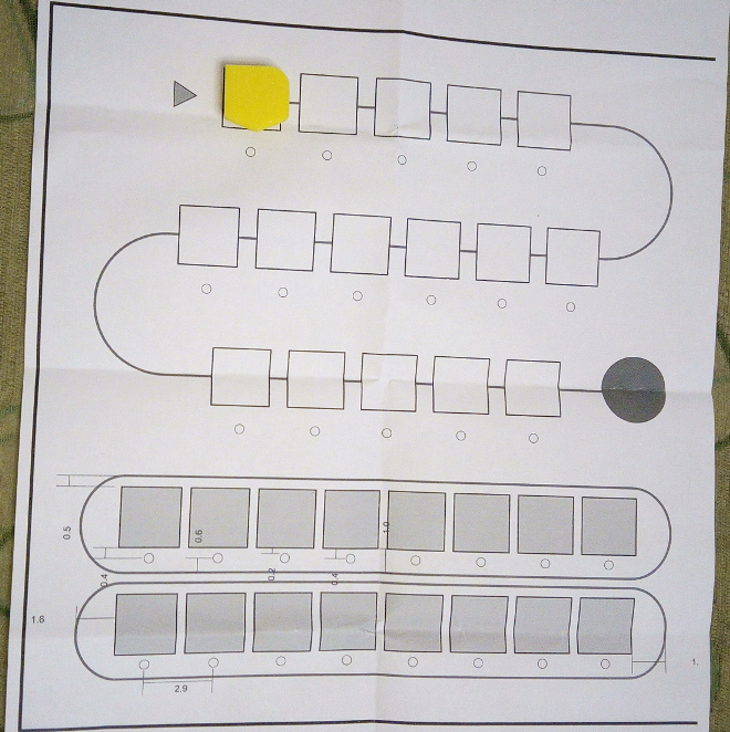
03/28/2017 at 12:39 • 0 commentsIn the original device, the controller had place for 16 blocks. It was divided into the main program with 12 blocks, and in the subroutine (function) with 4. I thought that this was too few. I wanted more, more in main program, in function, and wanted two independent subroutine. So I teamed up with a friend, who is a designer, and he designed the controller for me. It is not yet finished, there is a question or two, but it is in nicely advanced stage. I printed it out on a A3 paper. The dimensions are 30x30cm. Here is a picture of it printed out, with a programming block casually put on it:
![]()
The squares are 2.5x2.5cm, they are placeholders. The maximum size of the blocks will be this size. I am thinking of moving 1-1 block place from functions to the main program, but we will see how that version will look. So it will have 16 block for main program, and 2x8 for function, or 18 for main, and 2x7 for function.
The subroutine will have two pictograms, depicting the shape of the subroutine block's shape. But first I need to finalize the shapes :) The small circles are holes for the LED. It will give feedback, whether the block is inserted in his place and recognized, the execution of the programming block, and other, if I can think of something.
-
Programming blocks
03/28/2017 at 11:16 • 0 commentsThe next step were the programming blocks. The V1 had four: left turn, right turn, go forward, jump into the subroutine (function). The V2 got some new blocks added, the "negate" block, the backward block, and the random block. The first I didn't like, I am hesitant about the second, but the random block is interesting. For the first run, I will have the left, right, forward, random blocks, and two different subroutine blocks. I like the idea of two function.
Ok, the blocks are decided, but how will I produce it? In the V1, it was cut out from plywood, and glued together. In V2 it was injection molded. I did not want to make it from plywood, it would be too much laser cutting, and I did not have a laser-cutter. It means I would have to design it, go out somewhere to cut it out, then glue it together, and if I wanted to change something, then GOTO 10. And at the end, when I finally made the blocks right, I would need to paint them, because I like them colorful, but I don't like painting. Luckily it happened, that I have built a RepScrap Junkminator 2000 few months ago, and got some experience with it. So I started to design it. I am using a software called SolverSpace. I tried out a few, but find this program to be just logical, simple, understandable for me.
I have made the right turn, printed it out in one piece. I made a place at the bottom of the block, where to put the 1x1cm PCB. It looks like this:
![]()
-
Ideas about the Clone - part 2
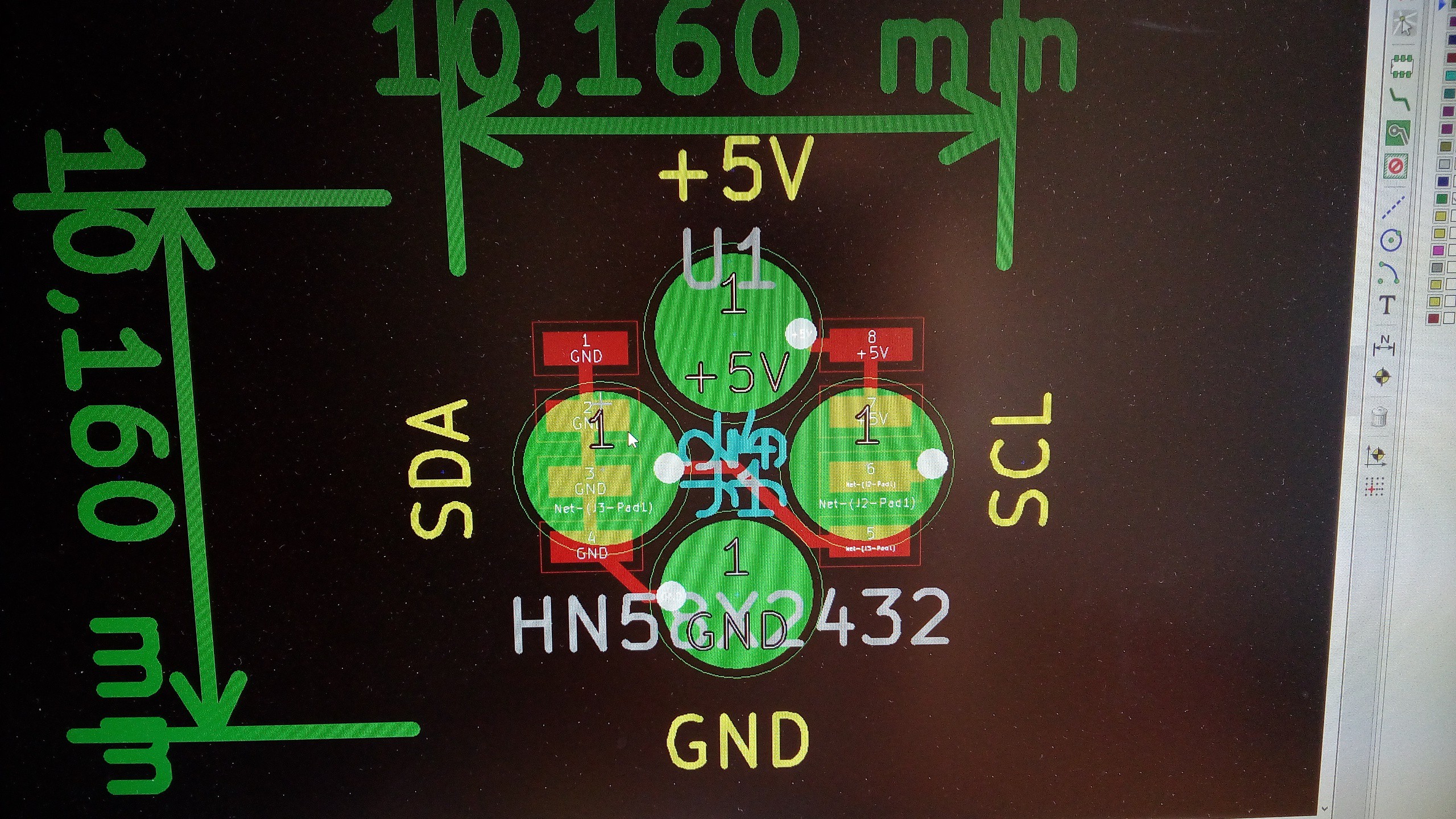
03/28/2017 at 09:37 • 0 commentsWell now, we have an ebay-ish pogo pins, but need the "other side" of the electrical contact. I was thinking, I will make a simple, two sided PCB. On the "upper" side, there would be the EEPROM, and on the lower side, I will put huge pads for the contacts. I looked around, and found out, that the OSHPark is making PCB-s with ENIG. I hope it will be sufficiently resistant.
Until this project, I was working in Eagle. But for a while, I was thinking of learning KiCAD. Well, there won't be better time for it, to start learning. So, I am trying to make the PCB in KiCAD.
I just sourced some Hitachi HN58X2432FP EEPROMs for 0.1$ per piece (4k x 8 bit), in 8 pin SOP package. I think its capacity is fairly enough :) This component isn't in the KiCAD's library, so I started with making it. Took some other SOP-8 package EEPROM, changed the relevant informations, rearranged a little the schematics pinout, to have my schematics look better. Made the board. I was calculating, that I need to have it somewhere in the 1x1cm size (in imperial it is PI/8 inch :) Ok, so I will panelize it, and cut it to the size. How will I cut it out to this size? Well, just like how I will panelize it in KiCAD: at the moment, I haven't the slightest clue. But I do have a picture of the board:
![]()
-
Ideas about the Clone - part 1
03/22/2017 at 14:23 • 0 commentsSometime in 2014 I read about this toy first. I didn't like the resistor solution. So, I was thinking, how to replace it with something new. And I was thinking, that the 12+4 places are a little few for my taste. I thought, I would add more places for the blocks. I felt the 4pc subroutine was too small, and just one subroutine was too little also.
The magnets came to an idea, but then I calculated, how many of them I will need, multiplied it with the cheapest source of HAL sensors, and I knew, they are out of my budget. Back to the drawing board. I couldn't find any solution, what did not required an electrical connection, and the same time it's costs wouldn't be prohibitory. OK, then it's going to have connections, but as little, as it is possible.
I came to idea of using 1-wire EEPROMs. Using it with only two wires (data+gnd) looked good. The V1 resistor solution had also two contacts, so it looked feasible. Search for the 1-wire EEPROMs gave price in the same range as HAL sensors. OK, so this is dead-end. I really don't know, why are those that expensive. For the price of 1pc of 1-wire EEPROM, I could buy a dozen of I2C EEPROMs, at least.
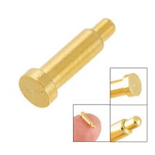
For the I2C EEPROM, there is at least 4 contacts to make. So I started to search for the solution to make those contacts fairly stable. I wanted something with a spring in it, to have a good contact. And then was an article about pogo pins, and it was like, that was the thing I was searching for. Ok, I have it, now source it somewhere. I ended up purchasing 3 packs of 50 pieces of it, off the ebay.
They looks like this:
![]()
-
What is this Cubetto
03/22/2017 at 12:00 • 0 commentsThe Cubetto first appeared on Kickstarter in 2013. The V1 was a DIY kit. The programming blocks contained a resistor. When inserted in "controller", it was a part of a voltage divider, and an ADC was measuring the voltage across it. Because there was only 4 different blocks, it was easy to differentiate between those different voltages. There was an Arduino Mega inside the "controller", with 16 analog inputs, so the "controller" had 16 places for programing. It was divided into 12 places for main program, and 4 places for subroutine. The 4 different blocks where: left turn, right turn, forward, jump to the subroutine. Later, the files for this version were uploaded to Github, you can find it here. In there, it is called "primo prototype". You can find all the information for rebuild, source codes, drawings for lasercuting, etc.
Last year the Cubetto appeared on the Kickstarter once more. But this time, it was a polished product. It looked much, much better. So it scored a whooping 1.6 million $ in funds. In this V2, the programming block had no more electrical connection to the "controller". There were 3 places for the magnets, and in the "controller" there is a PCB, size of the "controller", with HAL sensors, under the programming places. Different blocks had magnet(s) in different places, so by reading out the 3 HAL sensor, you could find out, are there some blocks, and what type are.
Cubetto Clone
I would like to build a re-engineered Cubetto clone for my son.