 Arnov Sharma
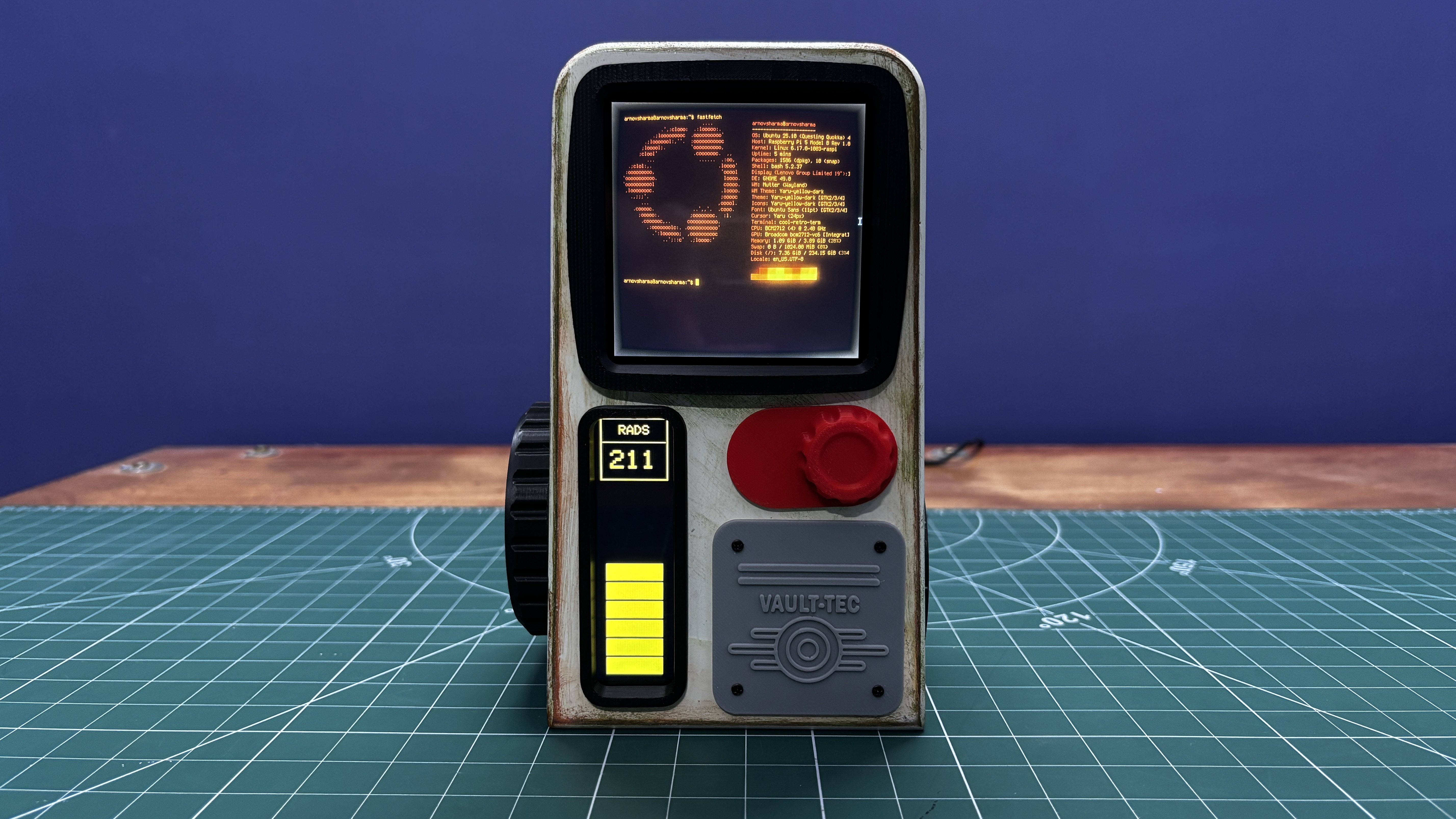
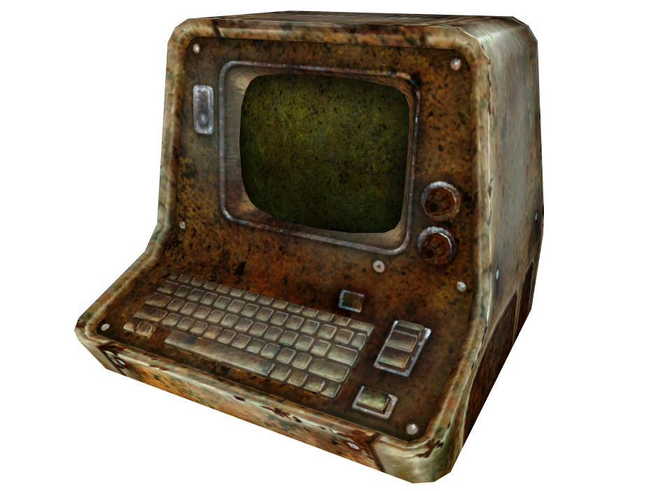
To make the build feel different and unique, I used a Square 4-inch waveshare HDMI display as the main screen, running a retro-styled terminal interface that closely resembles an actual Fallout terminal. This interface is an Ubuntu application called Cool-Retro-Term.
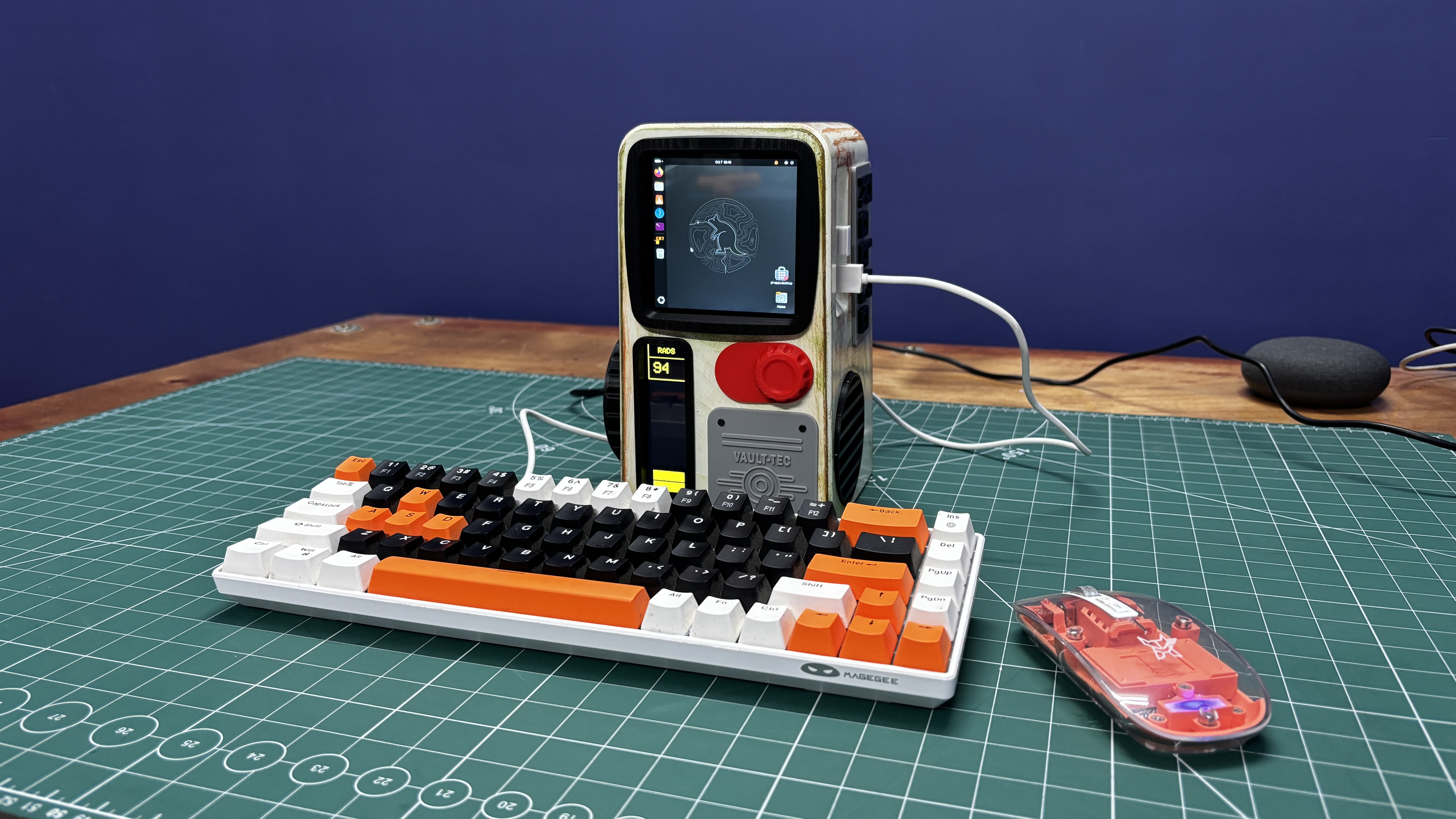
For the enclosure, I designed and 3D-printed the body, then painted and weathered it with artificial rust and mold patina. Small details such as knobs, logos, and surface greebles were added to make the terminal feel authentic, like a real piece of hardware from the Fallout world.
This article covers the complete build process of the Vault-Tec Air Terminal, from hardware and electronics to finishing and detailing.
So, let’s get started with the build.
MATERIALS REQUIRED
Following were the materials used in this project:
- Raspberry Pi 5
- M.2 PCIE Hat
- M.2 NVME SSD
- Waveshare 4-Inch HDMI Square Display
- TTGO T Display S3 Long
- 3D Printed parts
- DC STEP DOWN MODULE 5V 8A
- SGP40 Probe
- DC Barrel Jack
- Automotive Filler
- Red Oxide primer
- Sanding Equipment
- Beige Spray Paint
- Acrylic paint Brown and Green for Patina
- Acrylic Clear Coat Spray
INDOOR AIR QUALITY METER
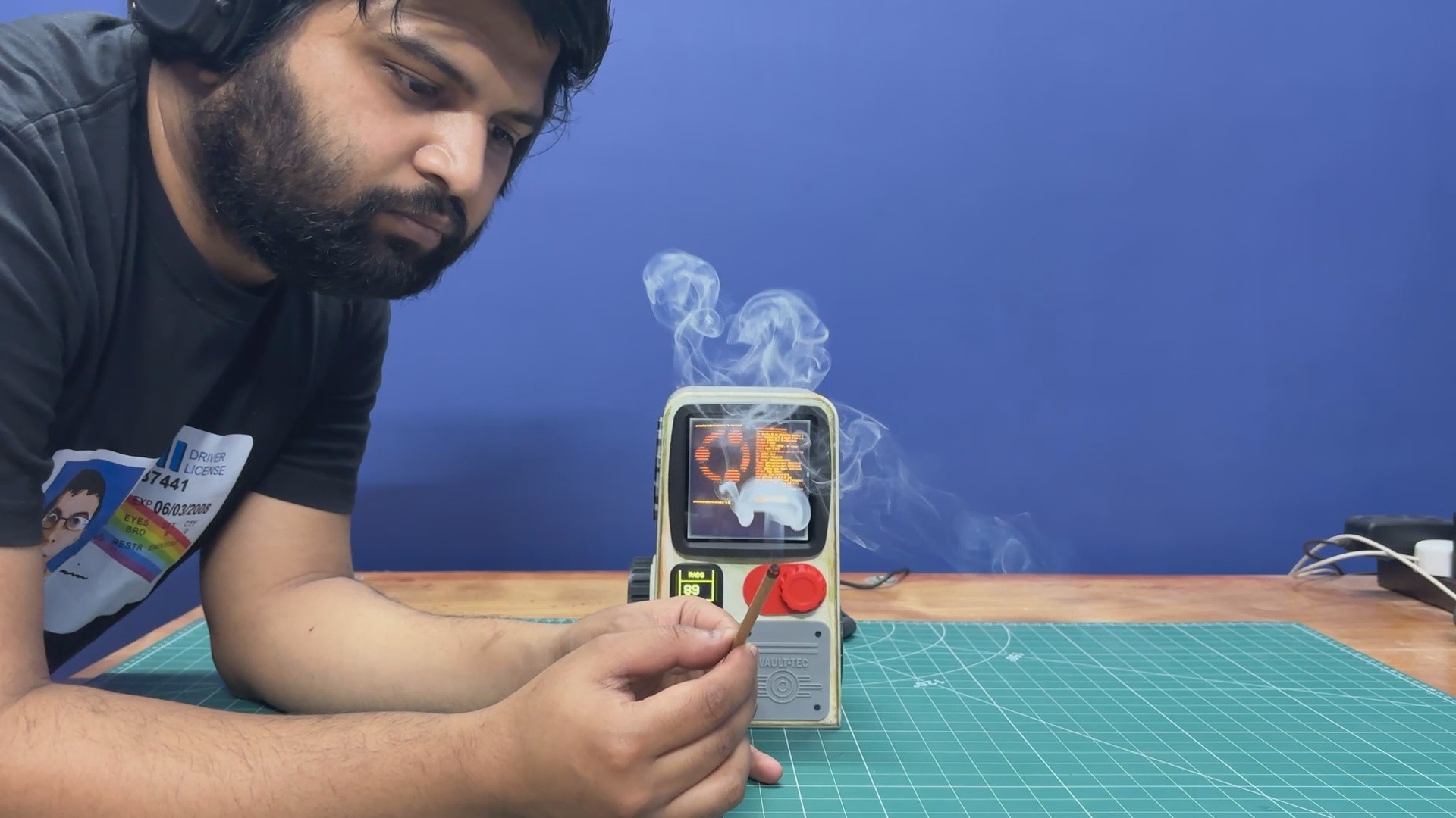
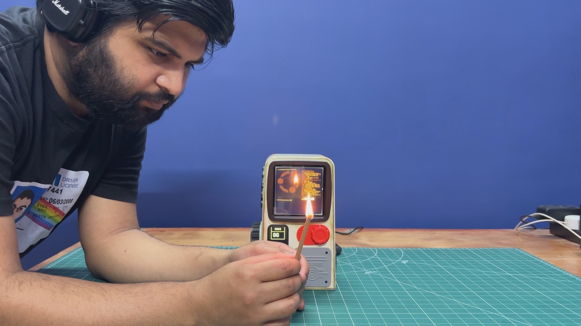
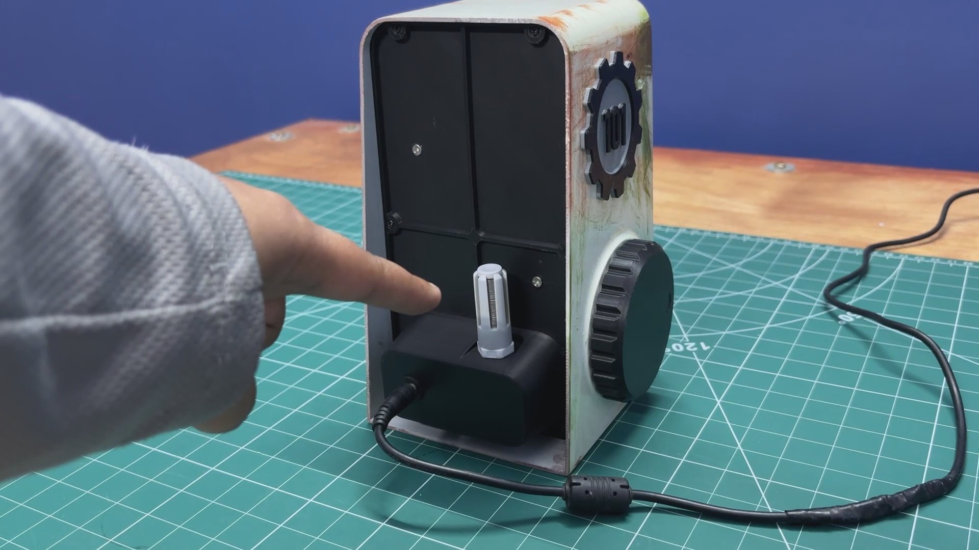
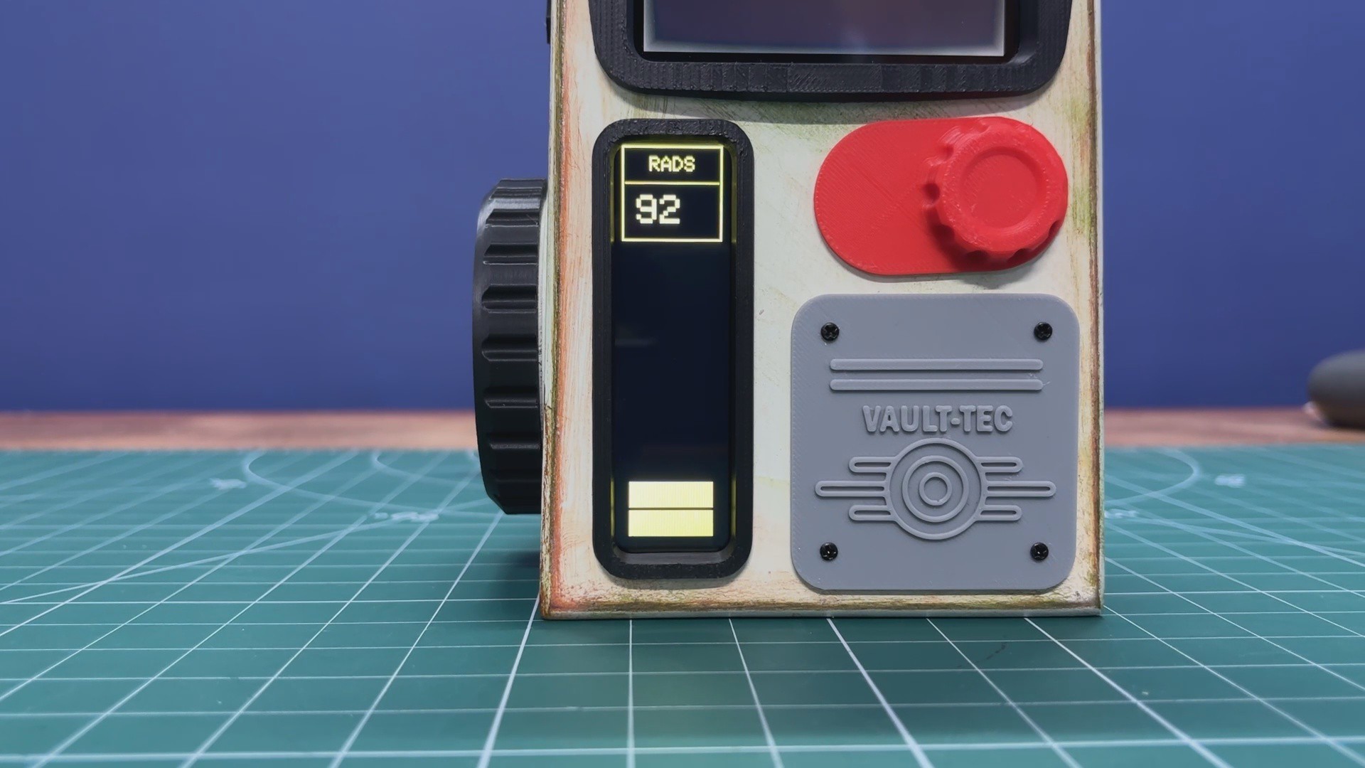
Here’s how the Vault-Tec Air Terminal’s air quality meter works. On the backside of the terminal, we added an SGP40 sensor housed inside a PG7 connector–based probe. The sensor continuously monitors the room’s air quality. Under normal conditions, my room’s air quality typically ranges between 50 and 100, which is displayed on the secondary screen.
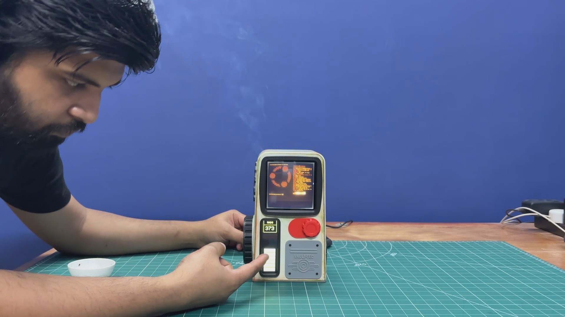
The UI is designed to replicate a Fallout-style aesthetic, using bar indicators and text labeled RADS as an homage to the Fallout universe. To demonstrate changes in TVOC levels, I lit an incense stick and placed it near the sensor. This significantly increased the TVOC concentration, which could be seen immediately as higher numerical readings and corresponding increases in the on-screen bars.
FALLOUT TERMINAL


The Fallout franchise is a retro-futuristic, post-apocalyptic RPG universe that mixes 1950s sci-fi optimism with the harsh reality of nuclear fallout. My entry point into the series was Fallout: New Vegas, and it immediately set the standard for me with its writing, atmosphere, and freedom of choice.
One of the things that fascinated me most about Fallout is how differently technology evolved compared to our real world. In this universe, transistors were never widely adopted. Instead, technological progress continued to revolve around 1950s-era vacuum tube technology, even as society believed it had reached an advanced future. This single divergence shaped nearly every aspect of the Fallout world.
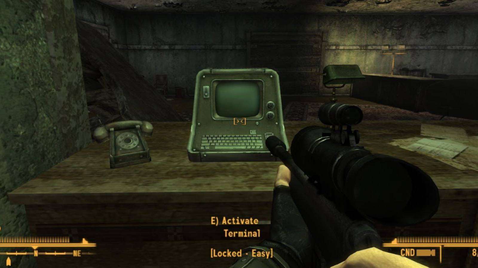
This is especially visible in Fallout’s computer terminals. They were never designed to be comfortable or visually appealing. Instead, they are purely functional machines, built for control, logging, and authorization. Interacting with them feels deliberate, using a physical keyboard to unlock doors, control turrets, access security systems, or read archived corporate and government communications.
Most of these terminals were developed by RobCo Industries, founded by Robert House, who also plays a major antagonistic role in New Vegas.
Physically, Fallout terminals feel imposing. Thick metal casings, exposed vents, mechanical switches and knobs, and the constant glow and flicker of CRT screens emphasize their electro-mechanical nature. They feel more like industrial control panels than consumer electronics. Even centuries after the nuclear war, many of these terminals still function, which suggests that while vacuum tube technology is inefficient and power-hungry, it is also incredibly resilient.
For me, these terminals are more than just gameplay mechanics. They act as storytelling devices, preserving fragments of the pre-war world. Reading emails, error logs, and security notices reveals corporate greed, government paranoia, and small, human moments frozen in time, often making the terminals feel like quiet witnesses to a world that no longer exists.
HARDWARE- DISPLAY
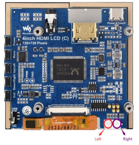
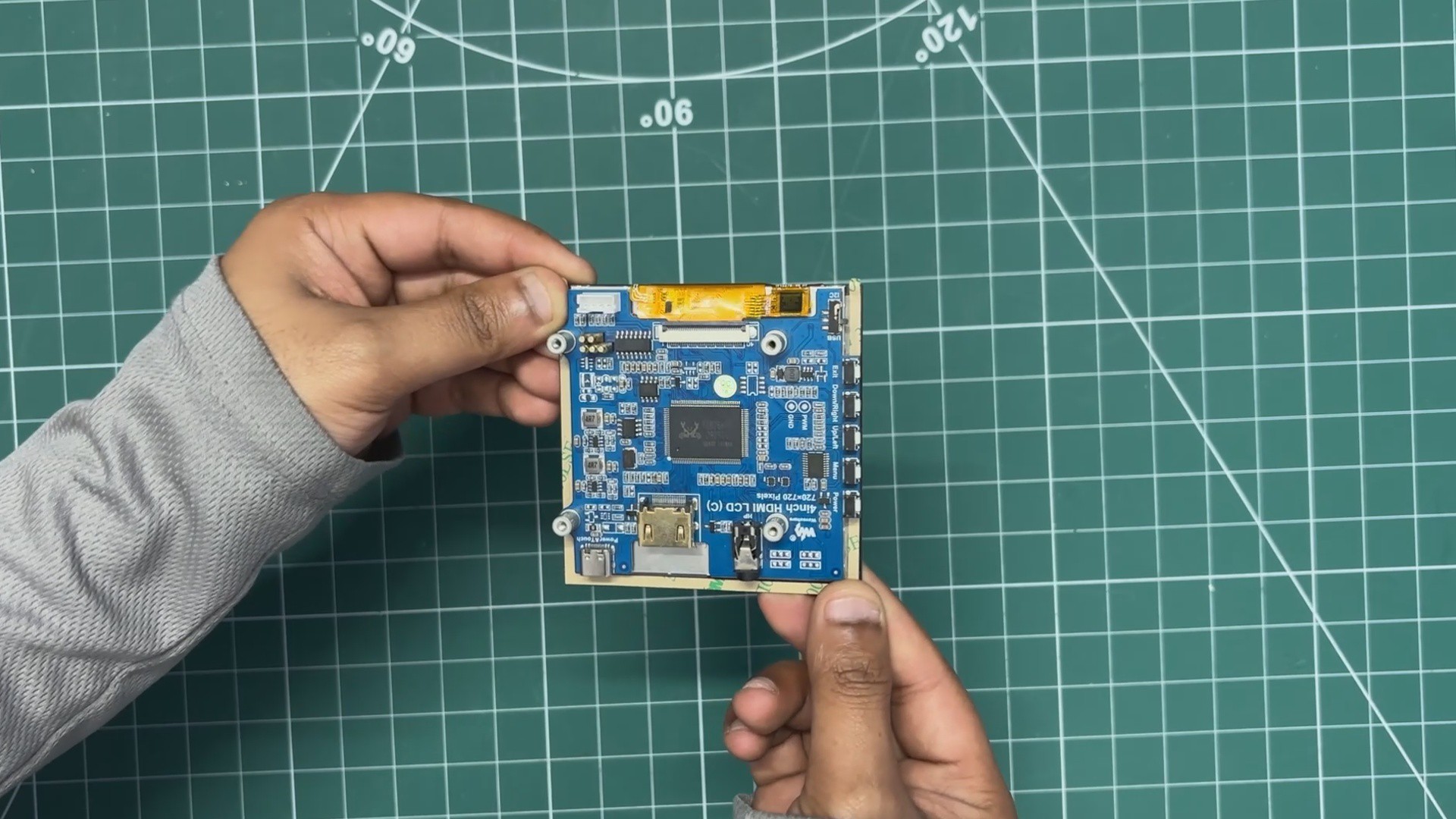
For this project, I wanted to break away from the usual rectangular screens, so I went with a unique 4-inch square HDMI display from Waveshare.
It features a 4-inch IPS panel with a hardware resolution of 720x720, paired with 5-point capacitive touch and a toughened glass panel rated up to 6H hardness. When used with a Raspberry Pi, the display supports Raspberry Pi OS and Ubuntu and works out of the box with no configuration or driver editing required.
The display can also function as a standard computer monitor, supporting Windows over HDMI.
It includes an onboard dual touch circuit with optional USB Type-C or I²C touch interfaces, allowing it to be used across a wide range of application scenarios.
In addition, the display provides a 3.5 mm audio jack and speaker interface, as it supports HDMI audio output, making it suitable for compact all-in-one builds without the need for external audio hardware.
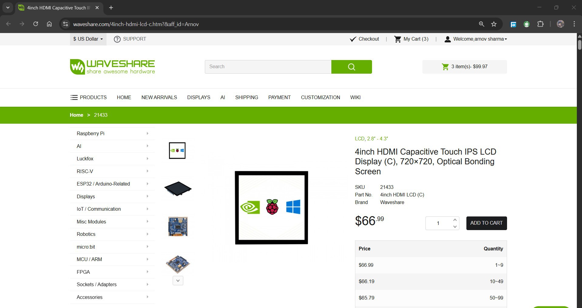
https://www.waveshare.com/4inch-hdmi-lcd-c.htm?&aff_id=Arnov
You can check out more about this display from its wiki page.
https://www.waveshare.com/wiki/4inch_HDMI_LCD_(C)
WAVESHARE SERVICE
Special thanks to Waveshare for providing the hardware used in this project. The 4-Inch HDMI Square Display and supporting accessories were supplied as review units for testing and evaluation.
Waveshare is a leading global provider of electronic components, modules, and development tools used across robotics, IoT, automation, education, and many other fields. With a strong focus on quality, reliability, and continuous innovation, Waveshare has earned the trust of engineers, designers, hobbyists, and makers worldwide.
Their extensive product lineup, from displays and HATs to expansion boards and embedded modules, makes them a go-to choice for both professional builds and DIY projects.
HARDWARE- RASPBERRY PI 5
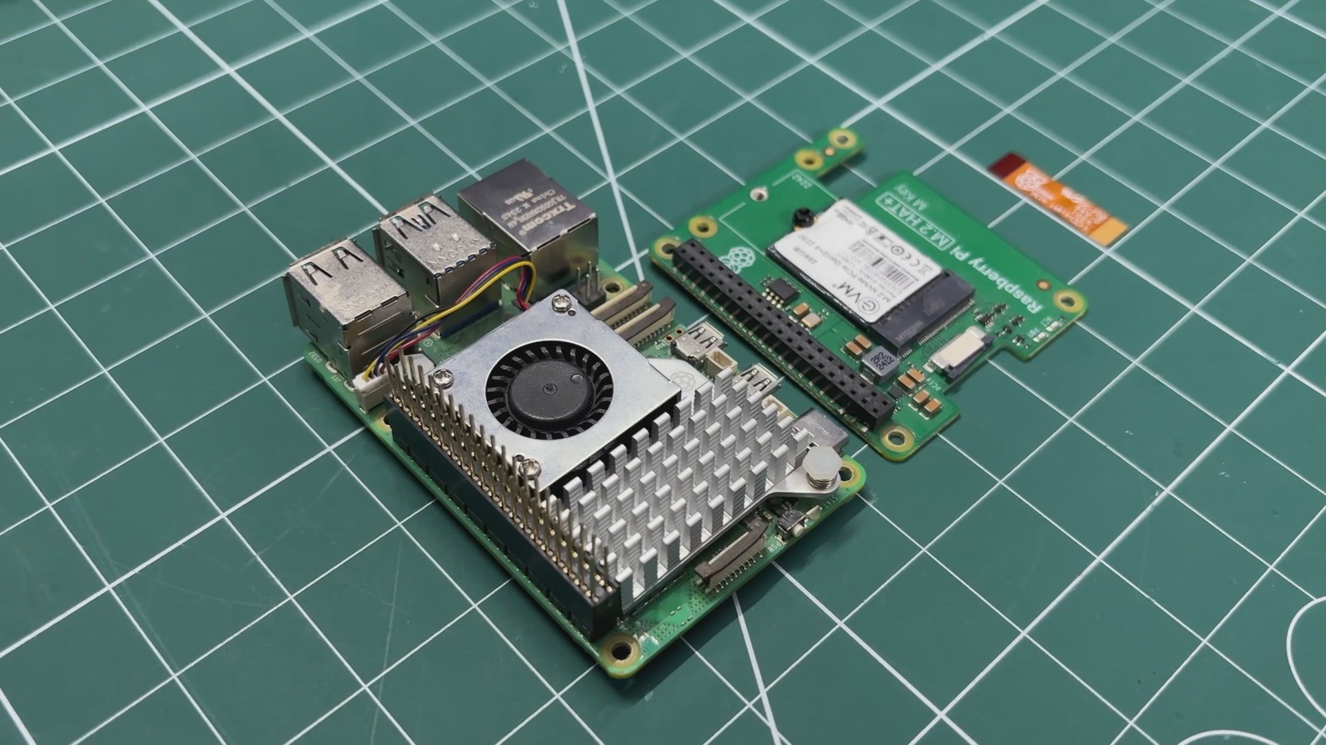
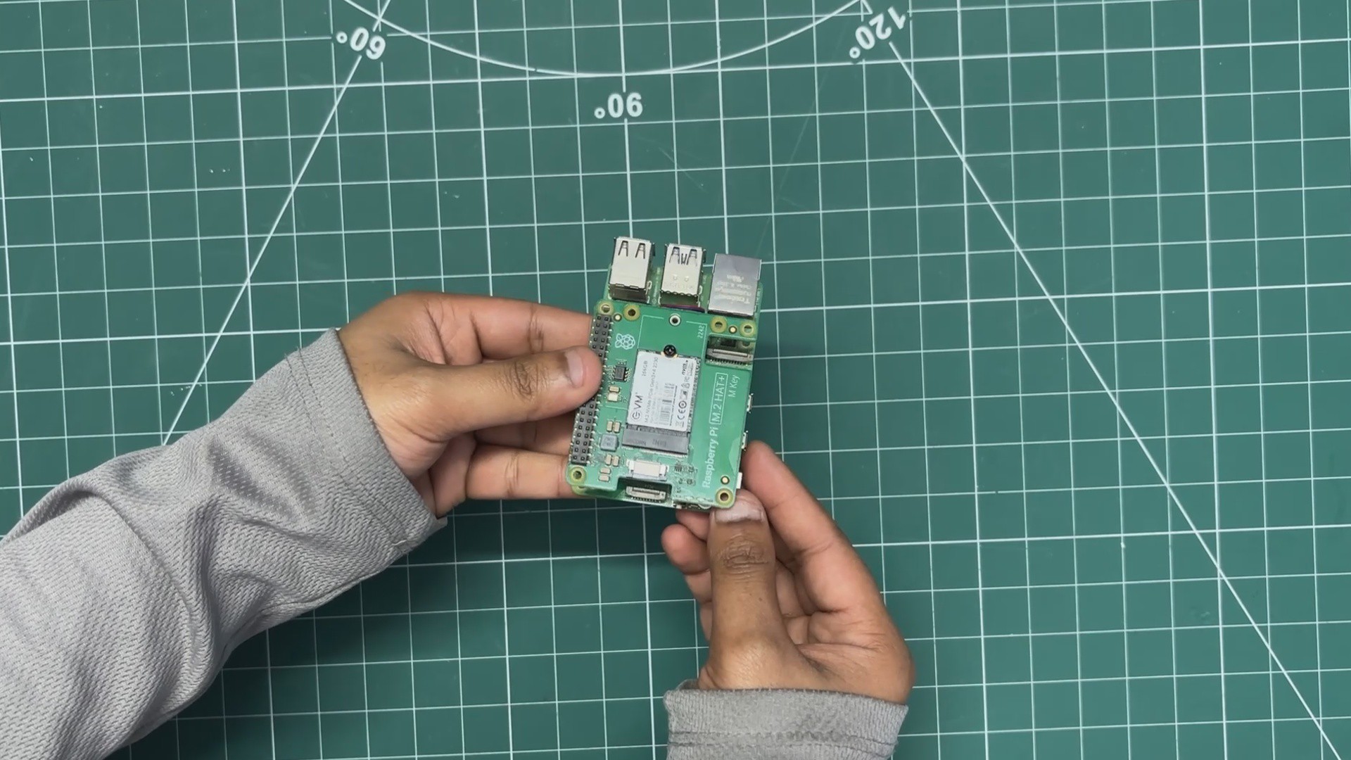
The brain of our terminal is a Raspberry Pi 5 (4 GB RAM variant). I selected the Pi 5 because of its compact form factor and improved performance. It is powered by the Broadcom BCM2712 quad-core Arm Cortex-A76 processor, which makes it a highly usable single-board computer.
To make the system even faster and more practical, I paired the Raspberry Pi 5 with the official Raspberry Pi M.2 HAT, fitted with a 256 GB M.2 Gen 3 NVMe SSD. Ubuntu is flashed directly onto the NVMe drive, and since the operating system runs from the M.2 storage instead of a microSD card, the overall setup feels significantly faster and more responsive.
HARDWARE - SECONDARY DISPLAY
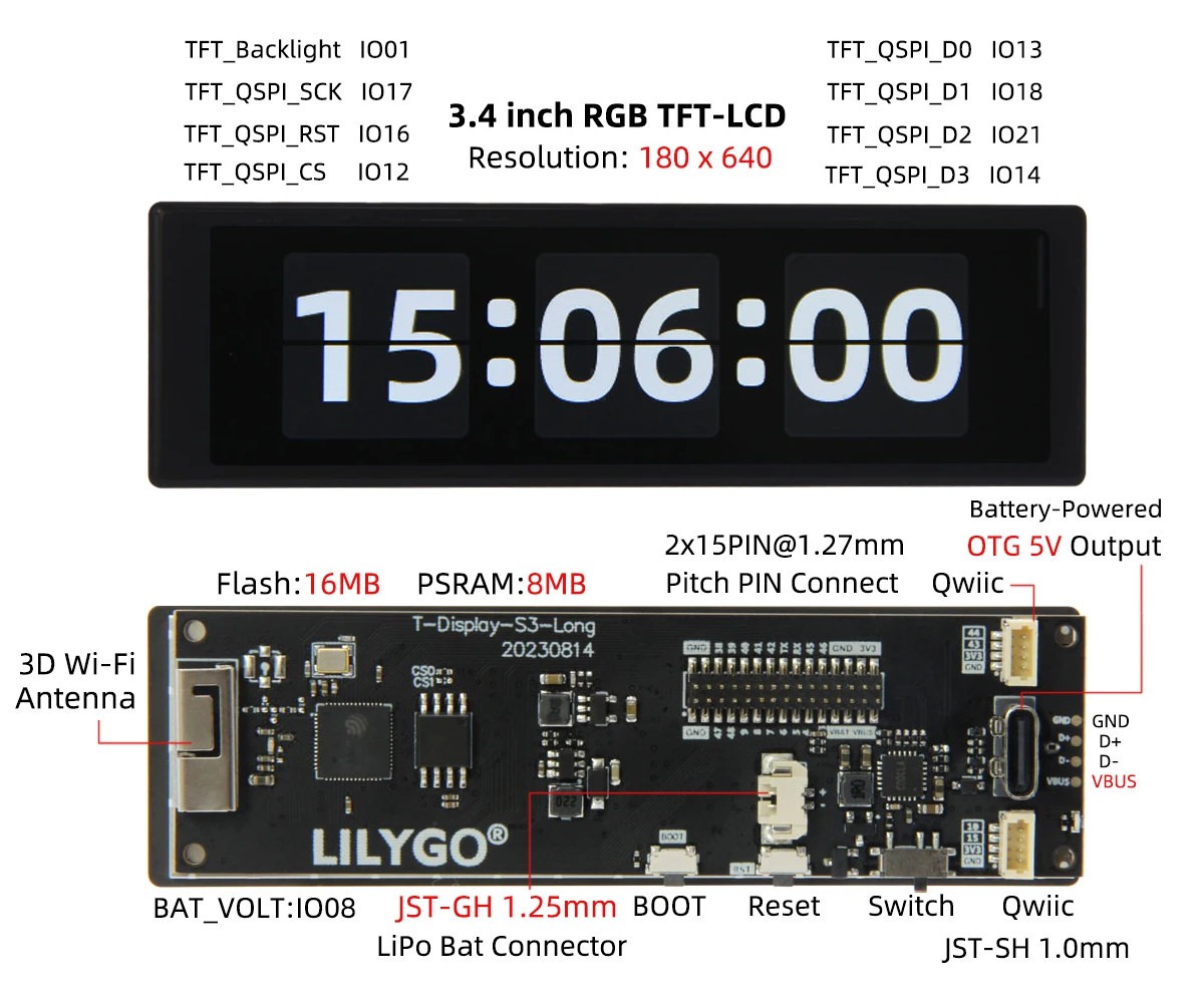
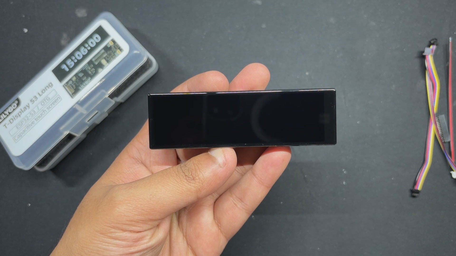
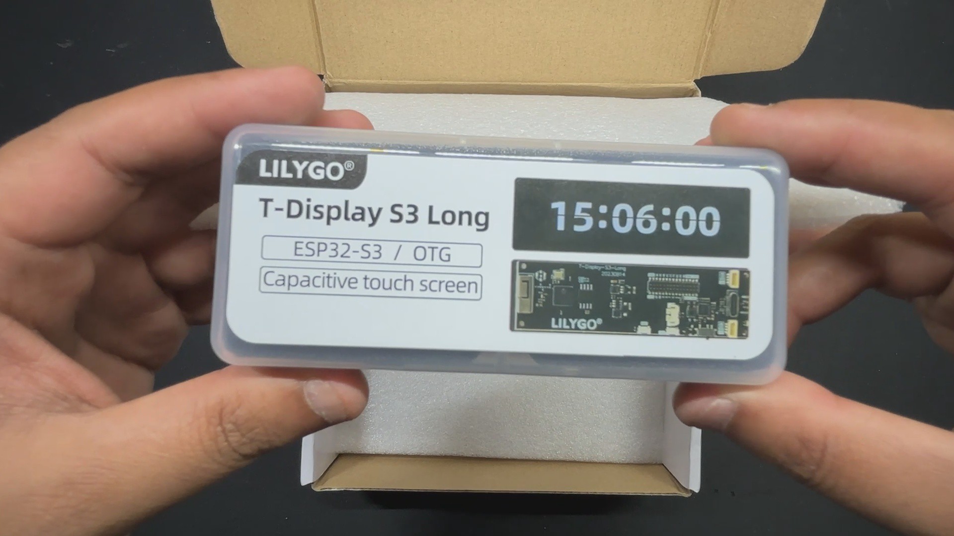
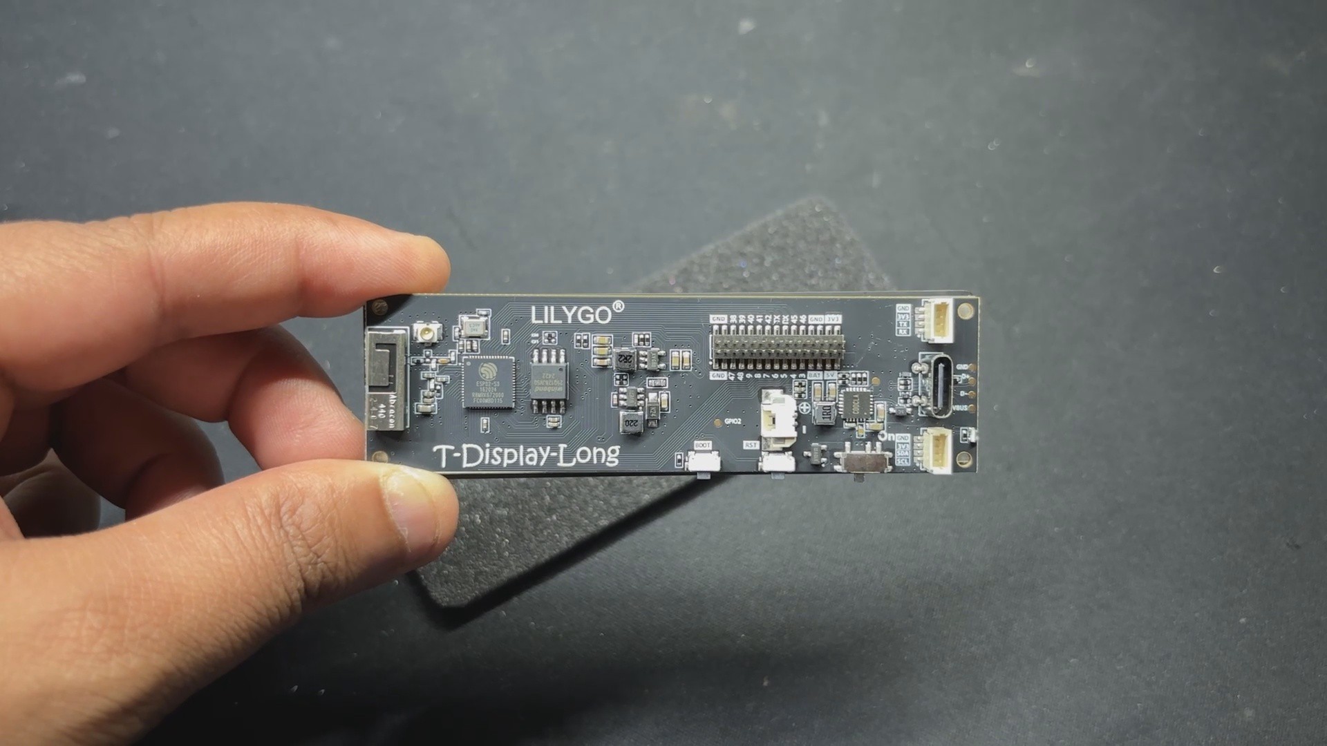
For the secondary display, we are using not a proper display but the TTGO T-Display S3 Long board, an ESP32-based development board that has a unique display. It is powered by an ESP32-S3R8 dual-core LX7 microprocessor and provides strong performance for demanding applications.
It has Bluetooth Mesh, BLE 5, and Wi-Fi 802.11. It can easily handle complex graphics and multitasking thanks to its 16 MB of flash and 8 MB of PSRAM.
Its most notable feature is the 3.4-inch capacitive touch TFT LCD, which uses a QSPI interface and has a 180 × 640 RGB pixel resolution, making it ideal for touch-enabled, long displays.
I use this board to pair the SGP40 sensor via the TTGO board’s I2C pins, connecting to the SGP40 I2C through a CON4 connector present on the back side of the board. The readings are then displayed on the 180 × 640 screen.
DESIGN INSPIRATION
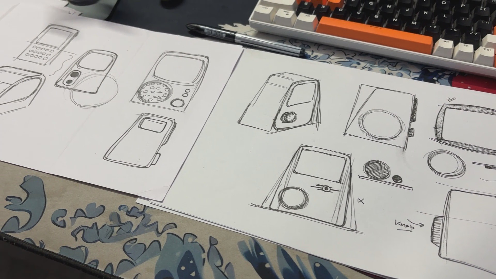
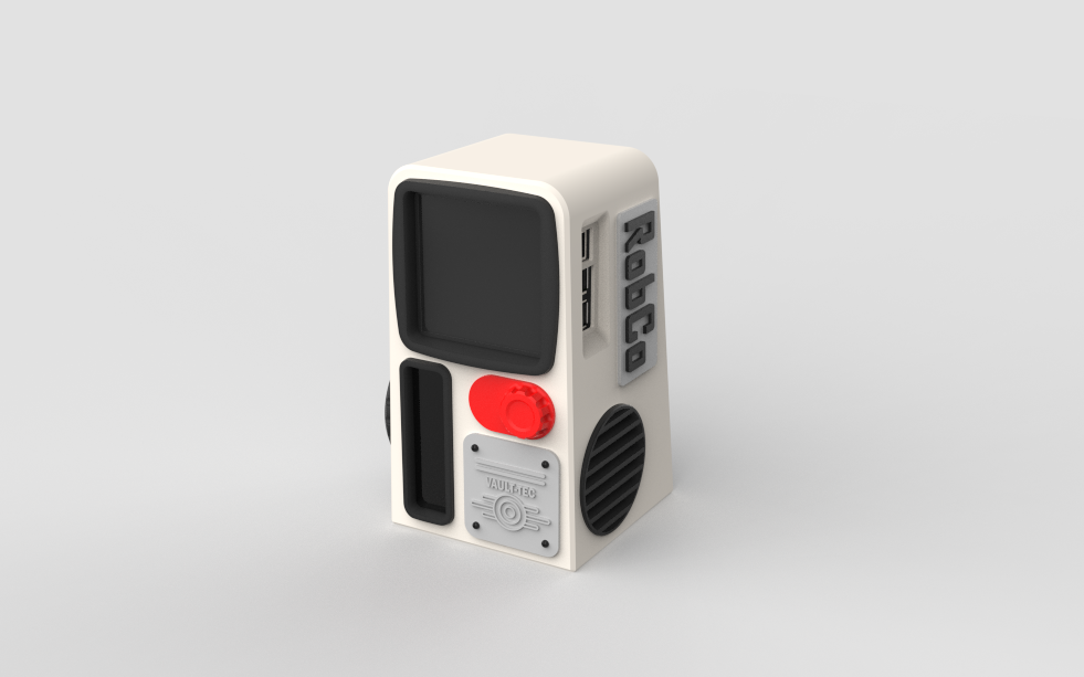
After doing thorough research on the design of several terminals from the Fallout universe, I studied the design language and the key elements that make a terminal stand out, one of the most noticeable being the screen borders that resemble old CRT monitor bezels.
I then created my own version, starting with several rough sketches. This entire ideation process was crucial for me, as I wasn’t copy-pasting an existing terminal model but designing my own version tailored specifically to the hardware I’m using.
My design uses a square display as the main screen, along with a second display to show air-quality readings. After experimenting with multiple design directions, I finally settled on the one I liked the most.
3D MODEL
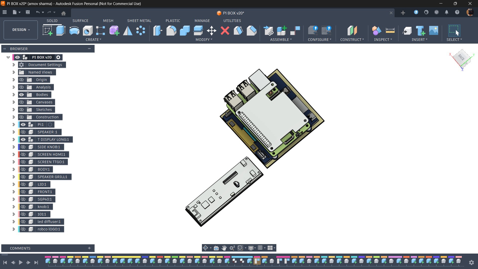
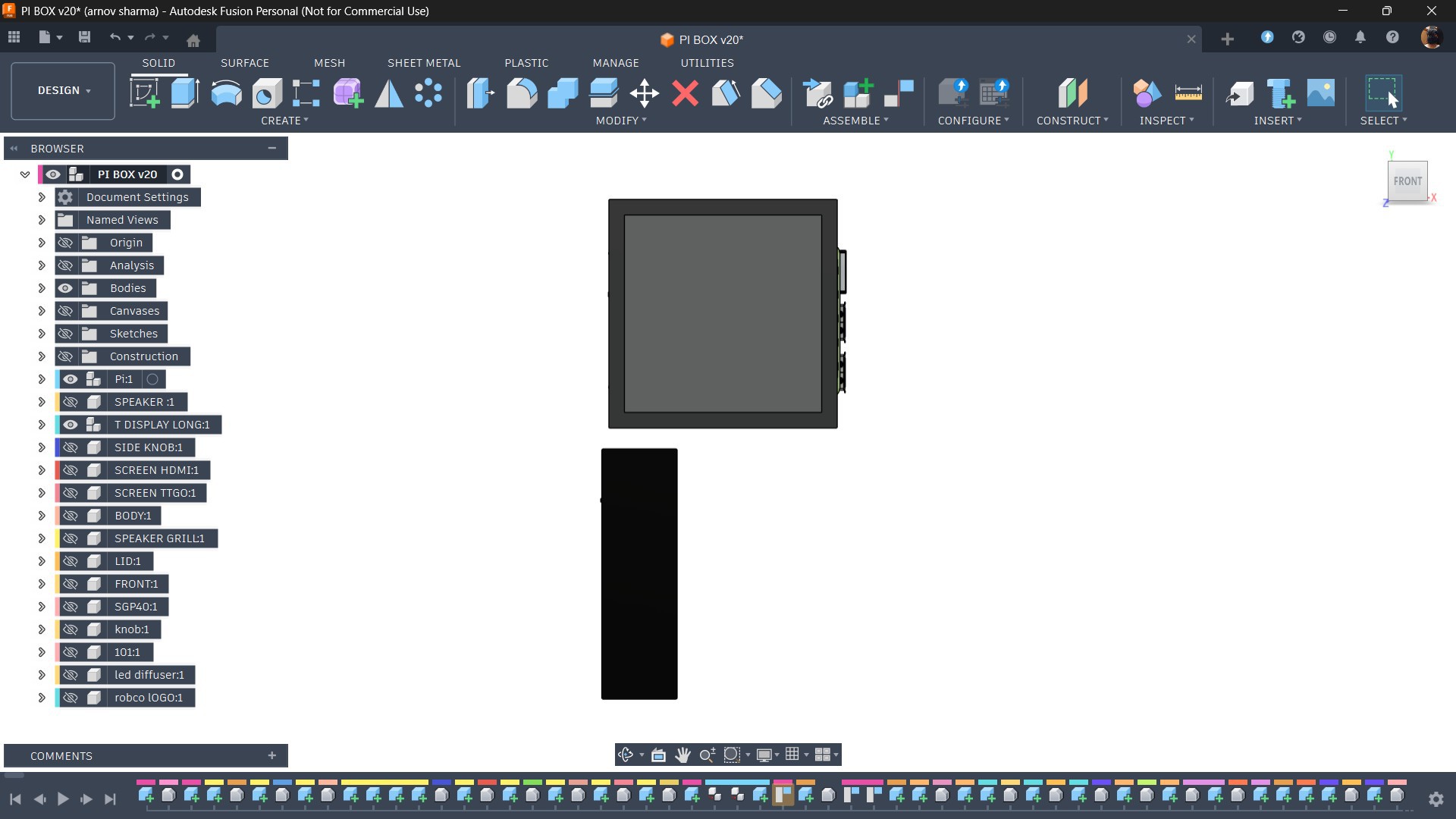
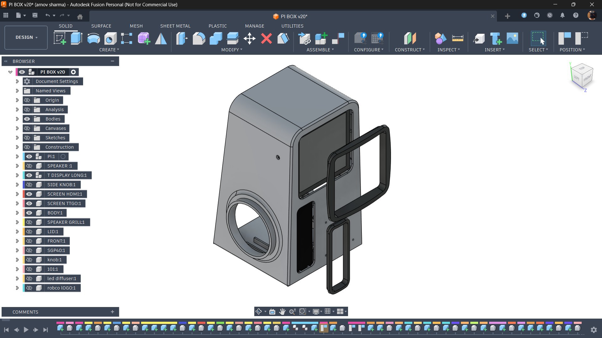
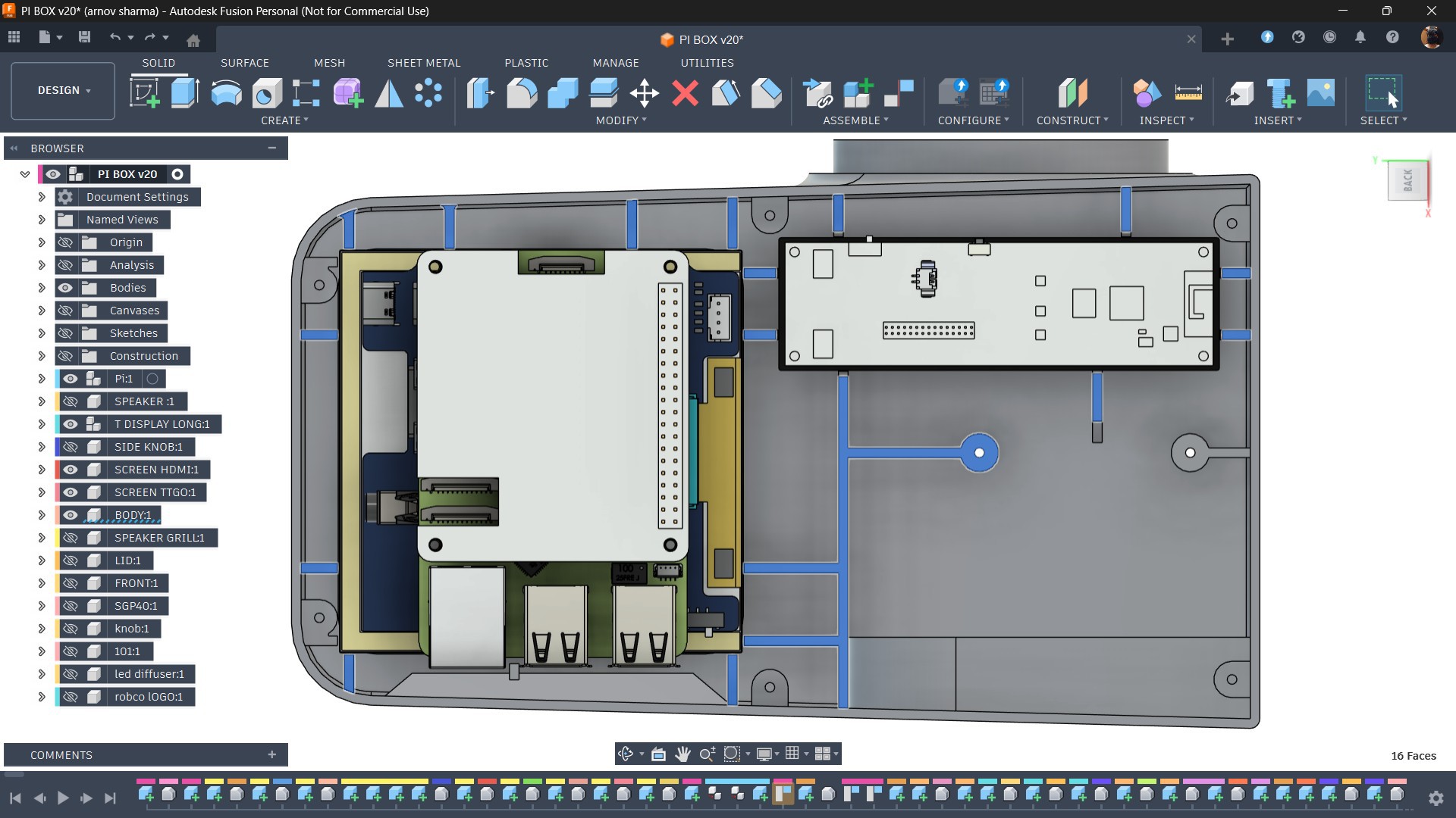
I started the 3D modeling process in Fusion 360 by importing the Raspberry Pi display setup along with the TTGO T-Display 3D model into my design.
From there, I followed my design idea and began sketching out the enclosure.
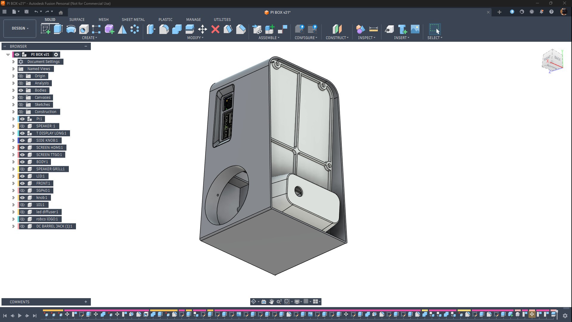
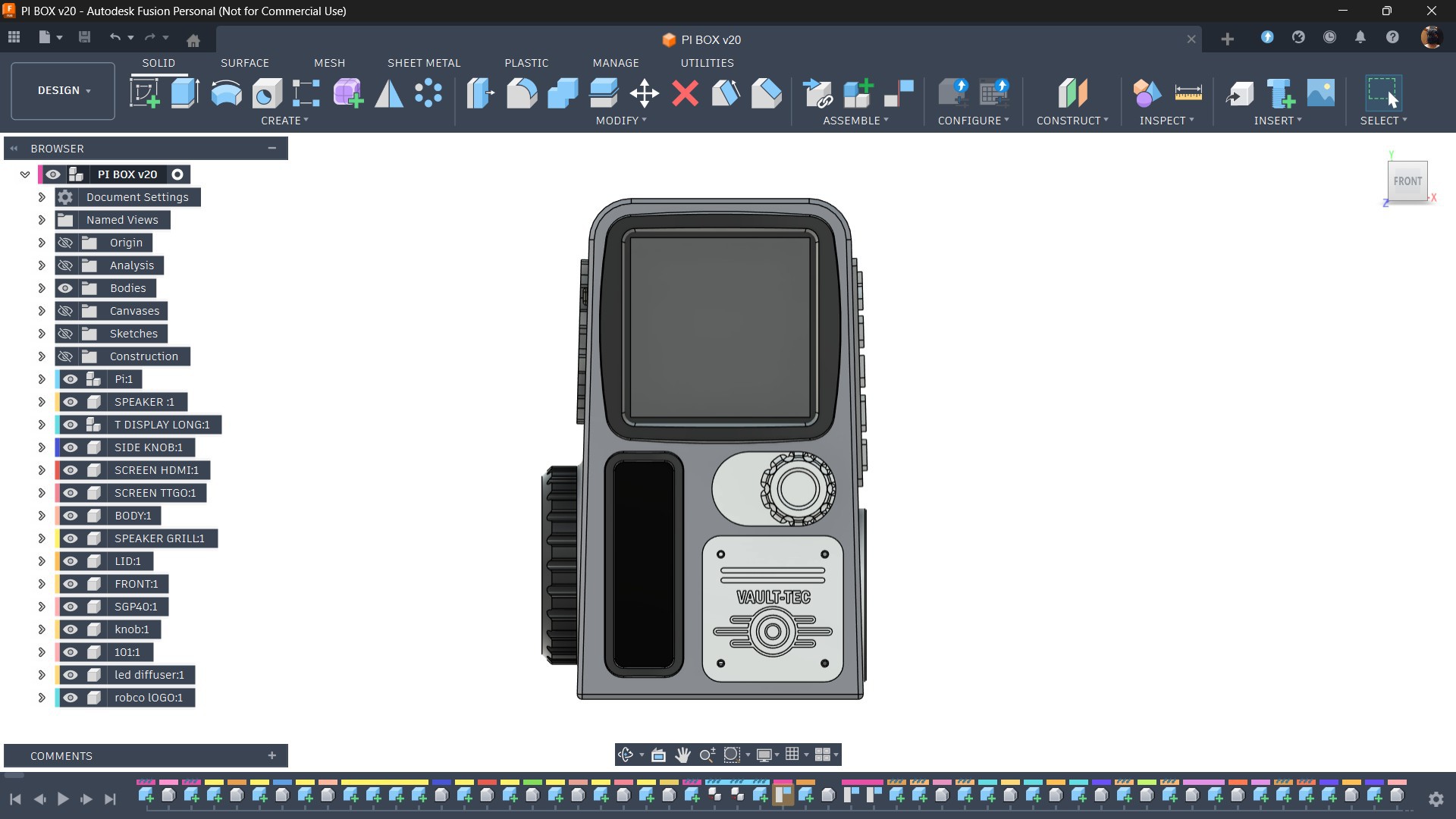
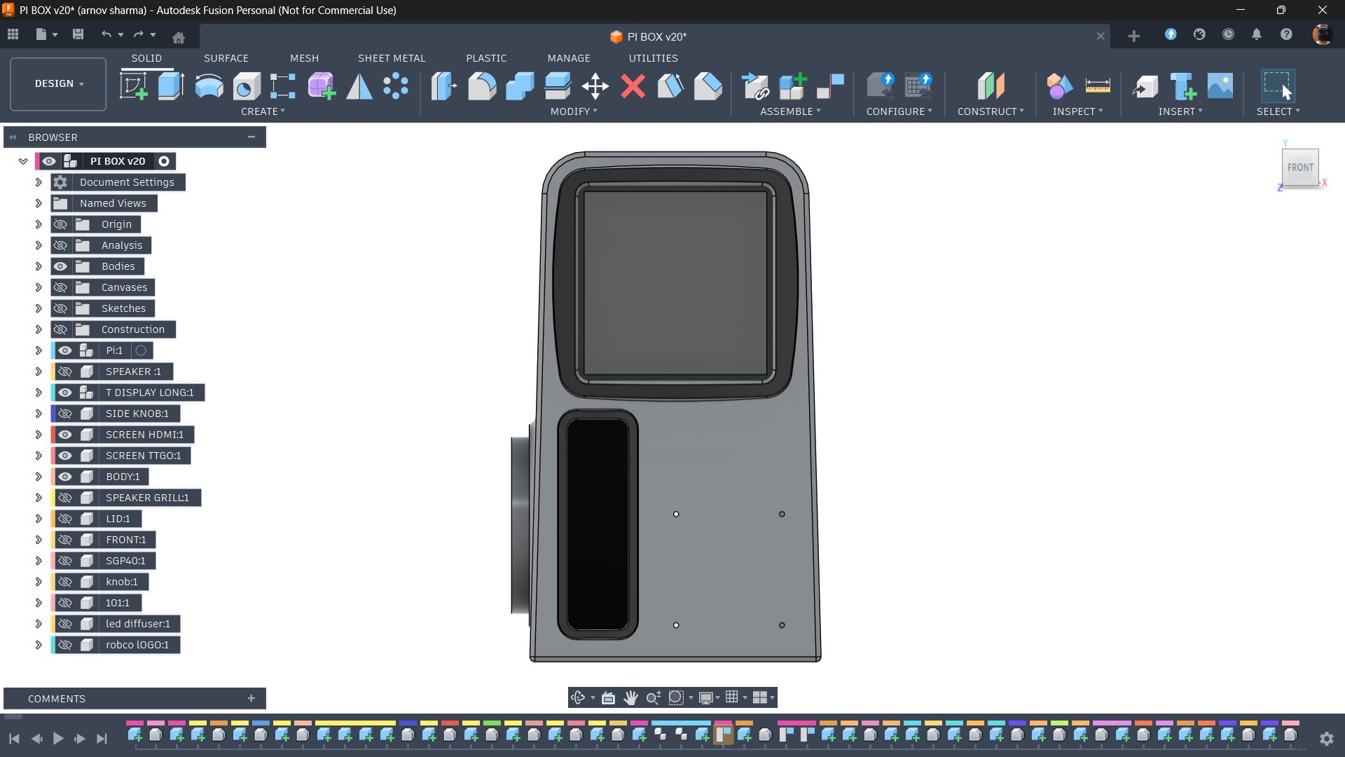
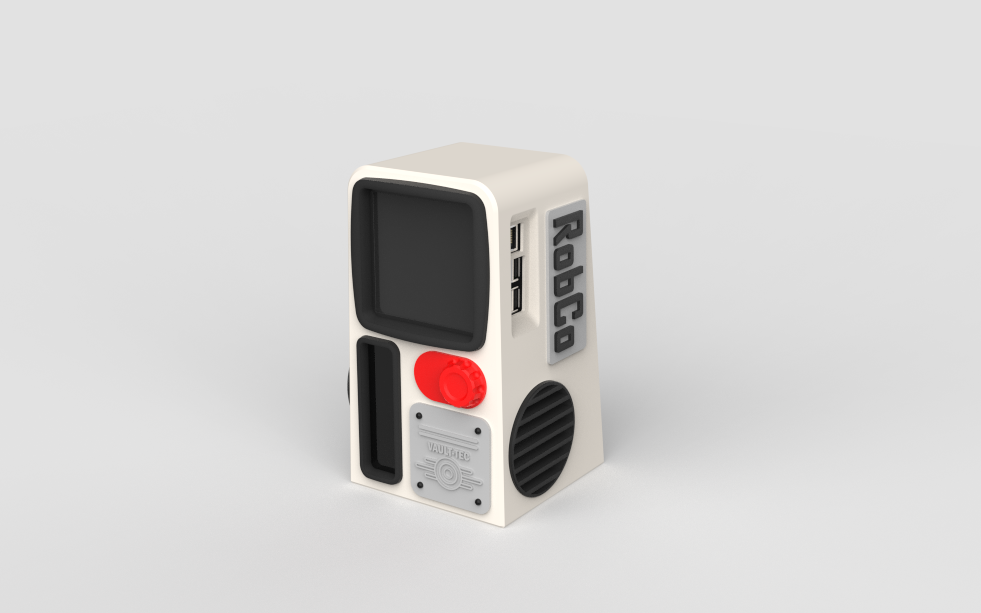
I modeled the main body first, making sure to include cutouts for the main square display and the TTGO T-Display board on the front side.
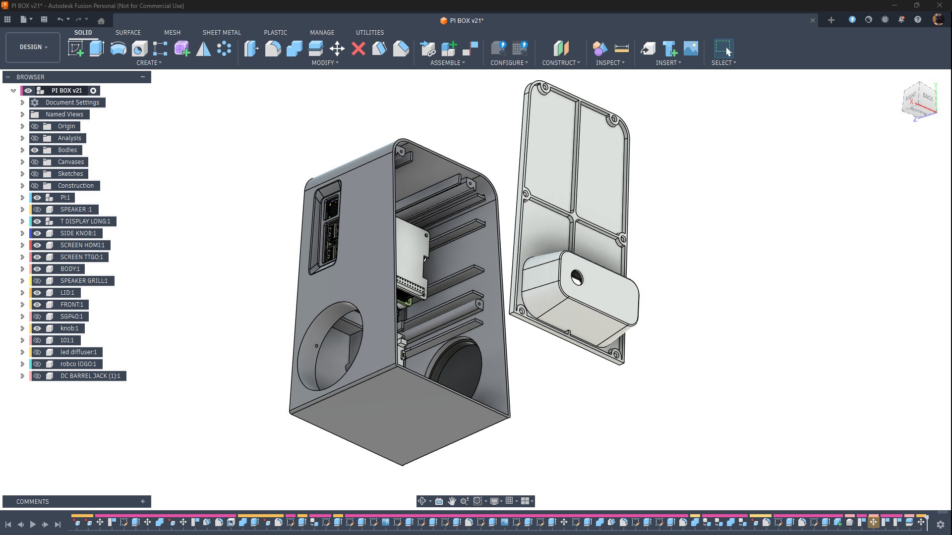
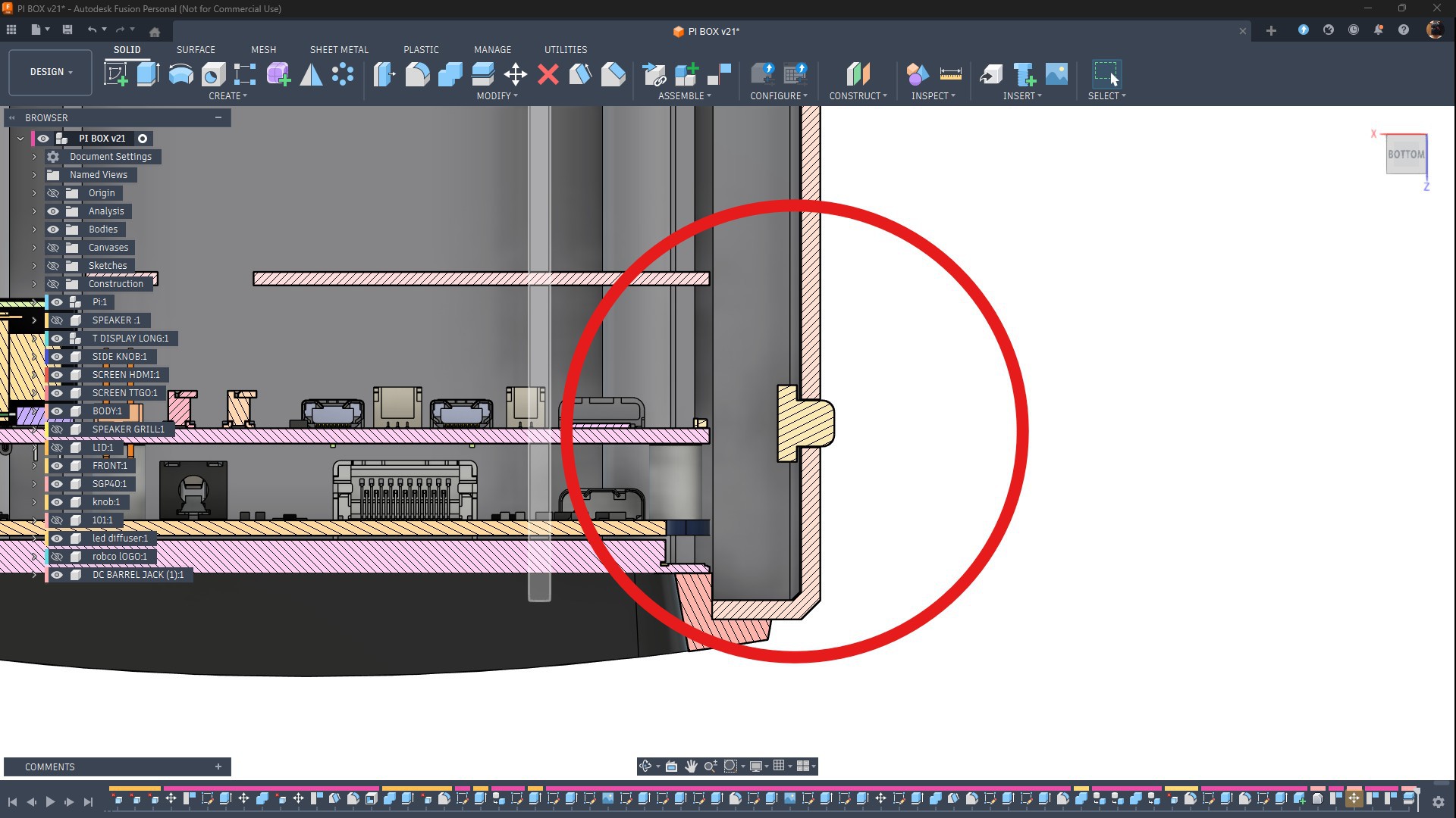
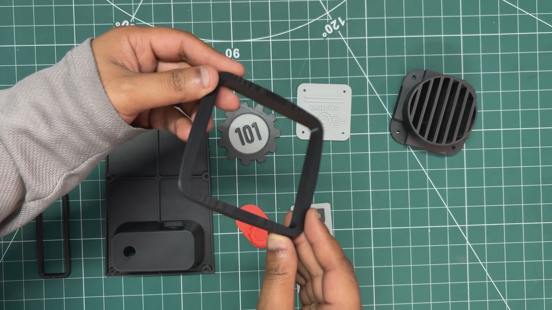
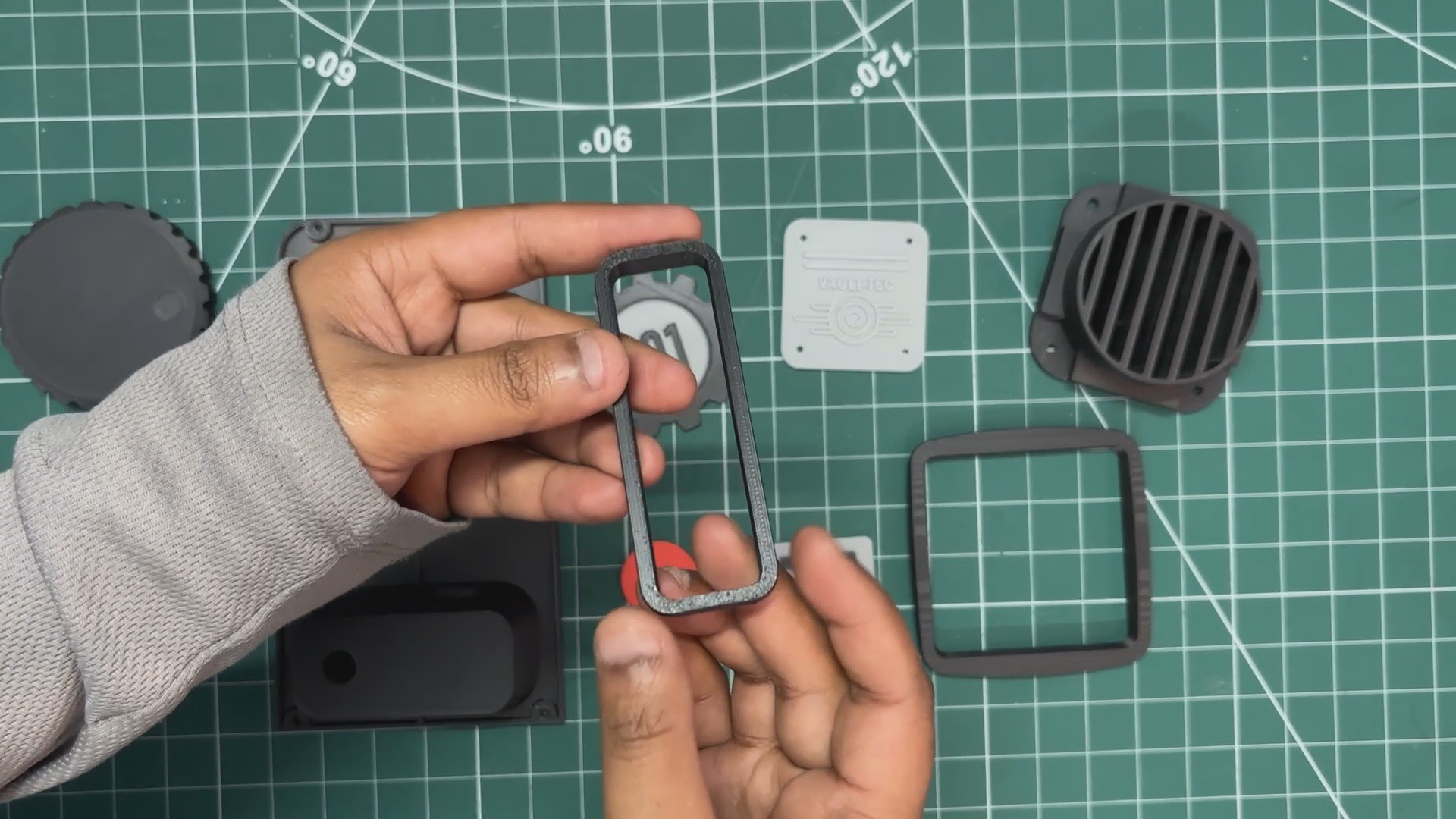
Next, I designed border frames for both the main and secondary displays. The idea was to make the screens look like old CRT-style monitors with thick display borders. These border frames were designed as separate parts so they could be 3D printed individually and then pressure-fitted into place.
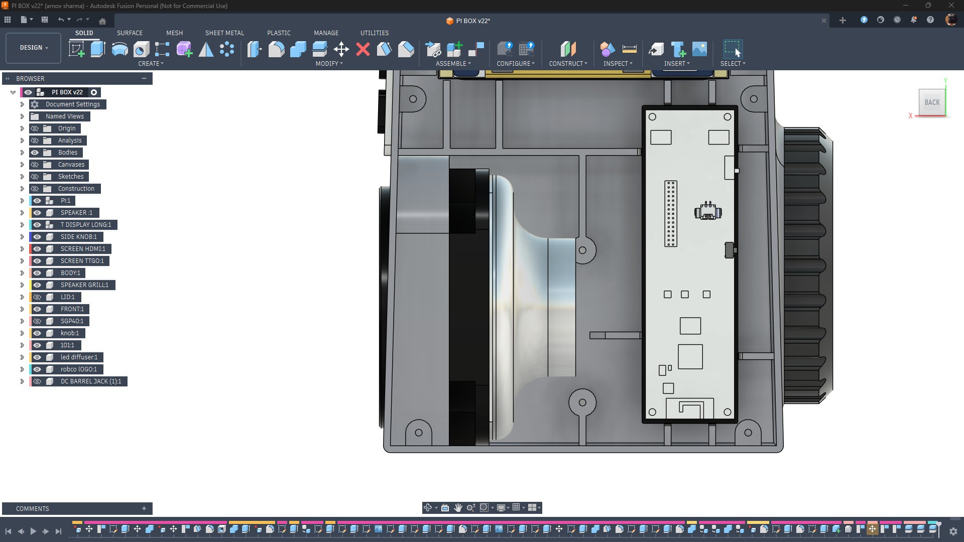
From the inside, I added ribs that help keep both the TTGO T-Display and the Raspberry Pi display setup in place. Since there was very little space, I didn’t make any custom screen holders.
Instead, my idea was to use a small amount of hot glue to secure everything—an approach I got inspiration for from James’s channel and his amazing (yet crazy) Xbox handheld build.
The ribs prevent the hardware from shifting, and the hot glue permanently secures the components in place.
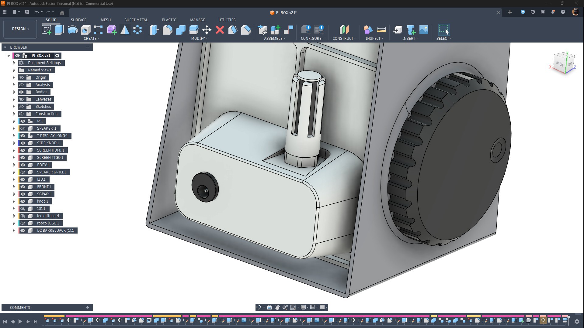
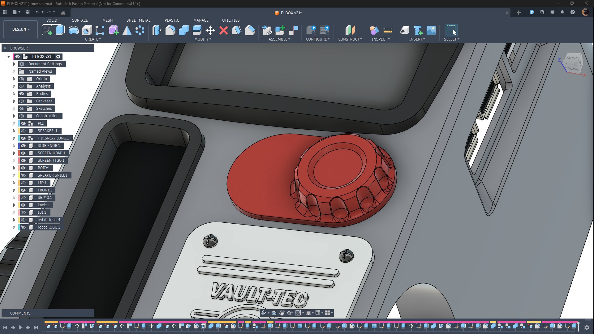
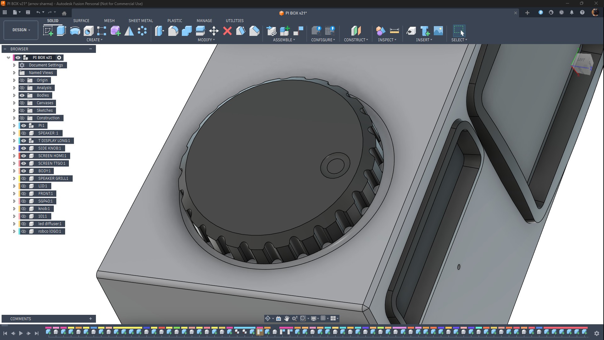
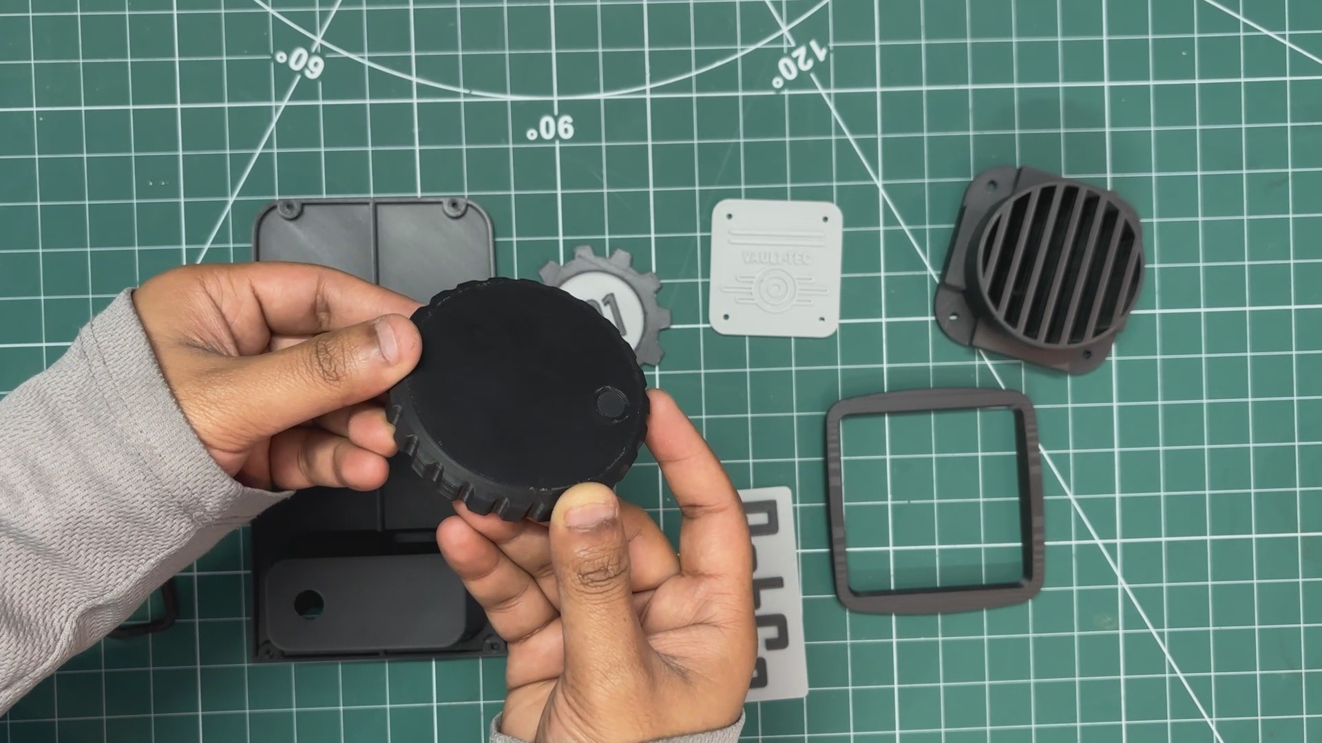
I modeled an extra-large knob on the right side of the main body. This knob is pressure-fitted into position.
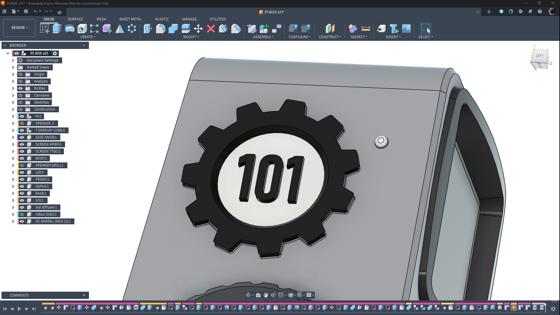
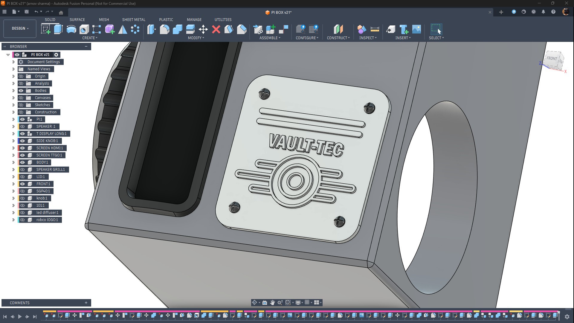
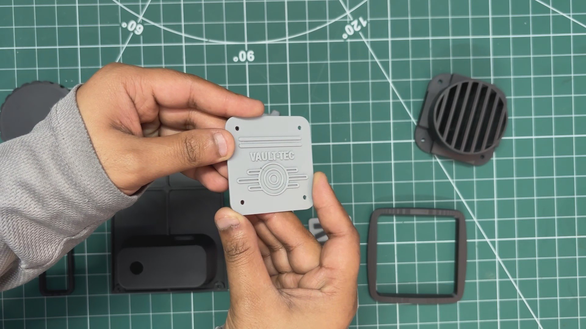
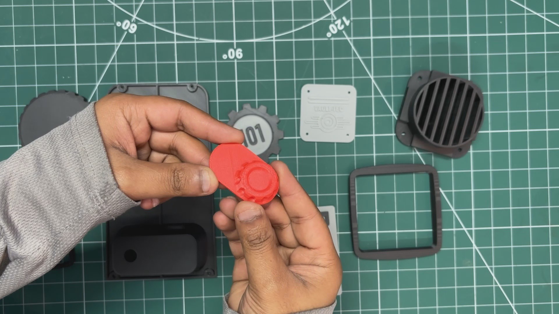
On the front face, I added a Vault-Tec logo, which is secured in place using four M2 screws. Slightly above the Vault-Tec logo, I placed a small knob-like part that I modeled purely for aesthetics. This part is printed in red to help it stand out visually.
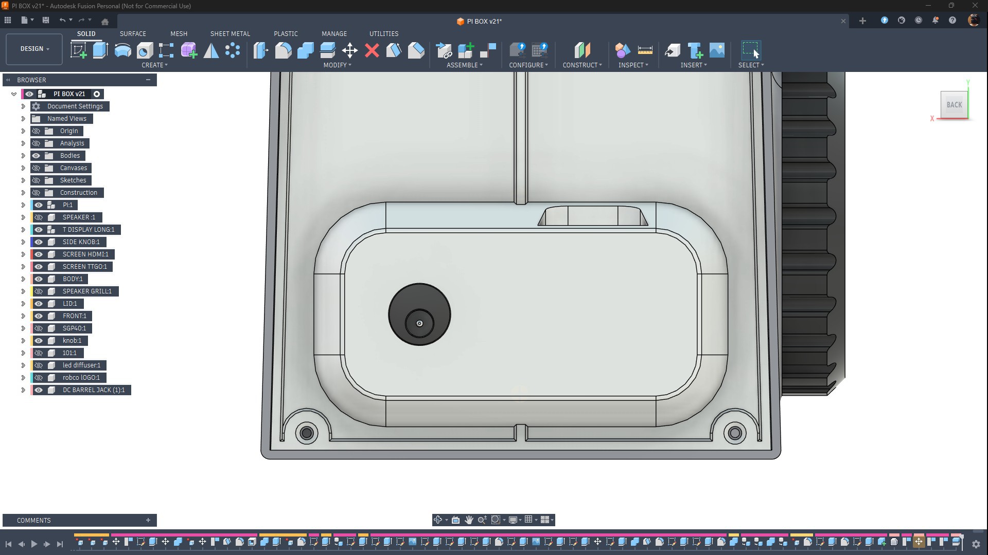
Next is the main lid, which serves multiple purposes. It holds the SGP40 sensor on the back side, includes a cutout for the DC barrel jack, and also acts as the enclosure lid itself. The lid has six mounting holes, allowing it to be secured to the main body using six M2 screws.
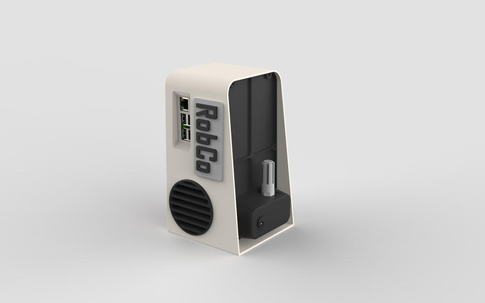
The Raspberry Pi has a status indicator LED that turns green from red once the Pi boots. To make this visible, I designed a small opening on the right side of the body aligned with this LED. A diffuser part, printed in transparent PLA, is placed in this opening so the LED glow diffuses through it and becomes visible from the outside.
Above the large knob on the right side, I added a Vault 101 logo. This logo is purely aesthetic and is secured in place using superglue.
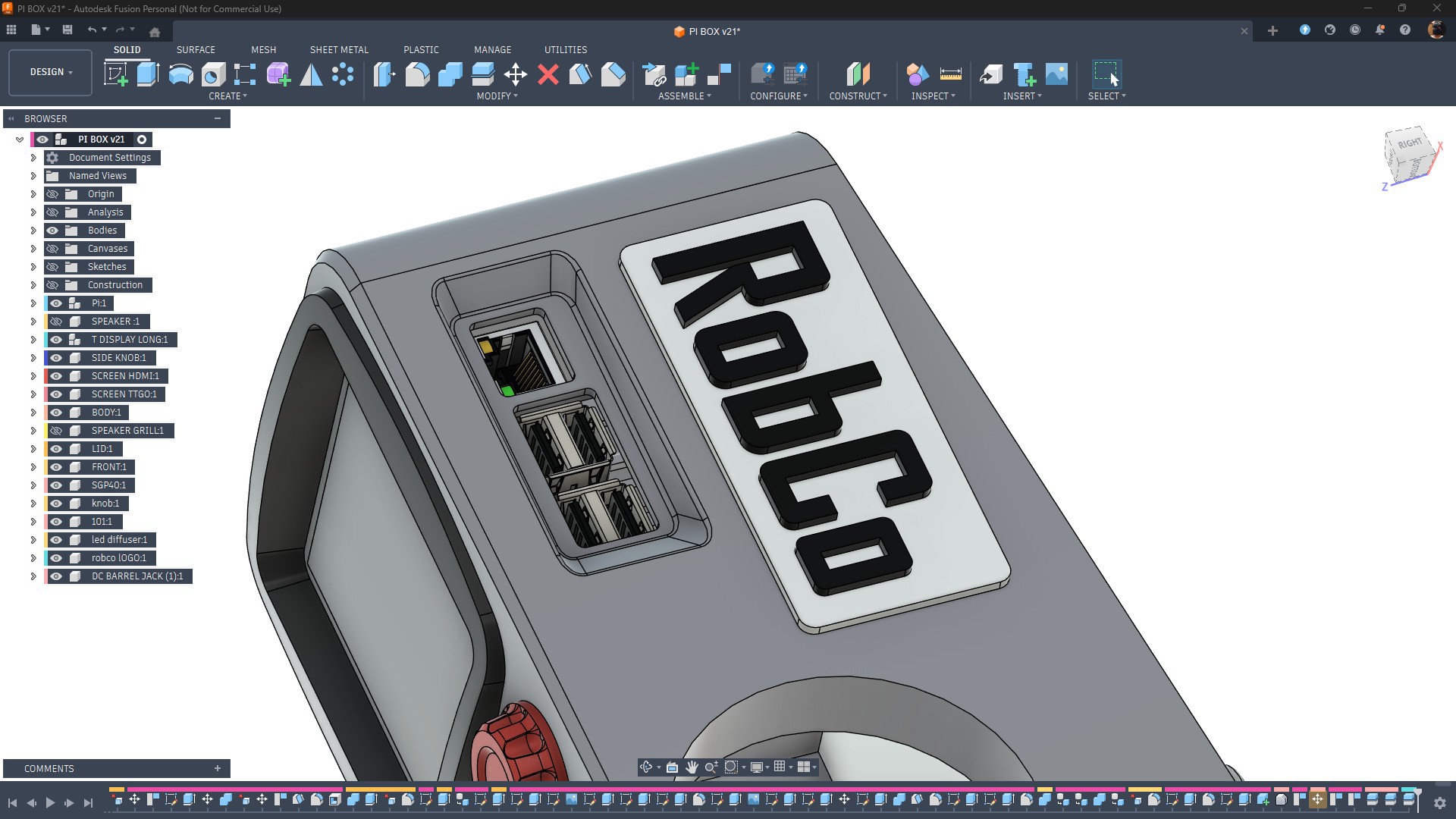
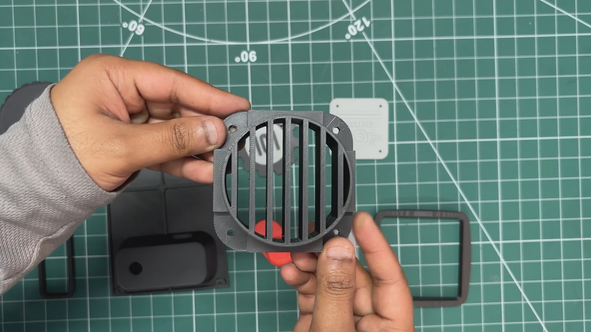
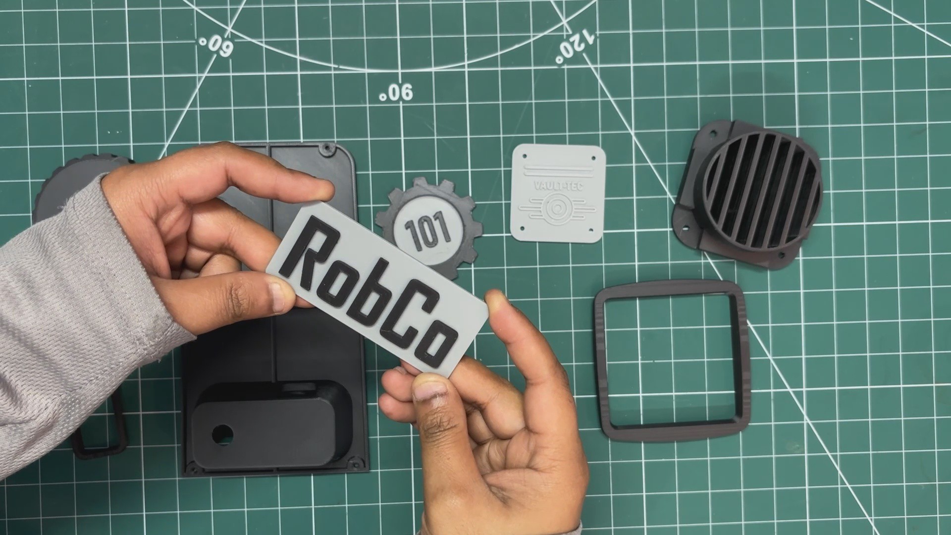
On the left side, slightly near the I/O opening, I added a ROBCO logo, which is also secured using superglue. Below the ROBCO logo, I added a speaker grill. This grill holds the speaker in place, and both the speaker and grill assembly are pressure-fitted into the main body. From the outside, the grill sits slightly flush with the body, giving it a clean, integrated look.
3D PRINTED PARTS
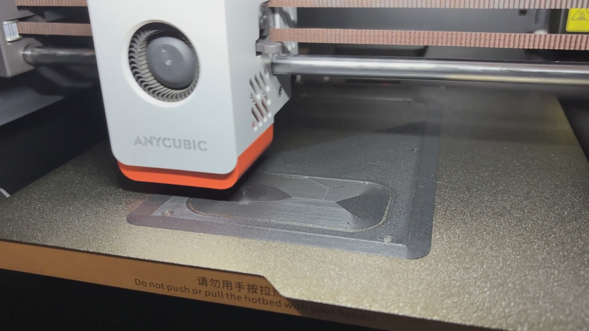
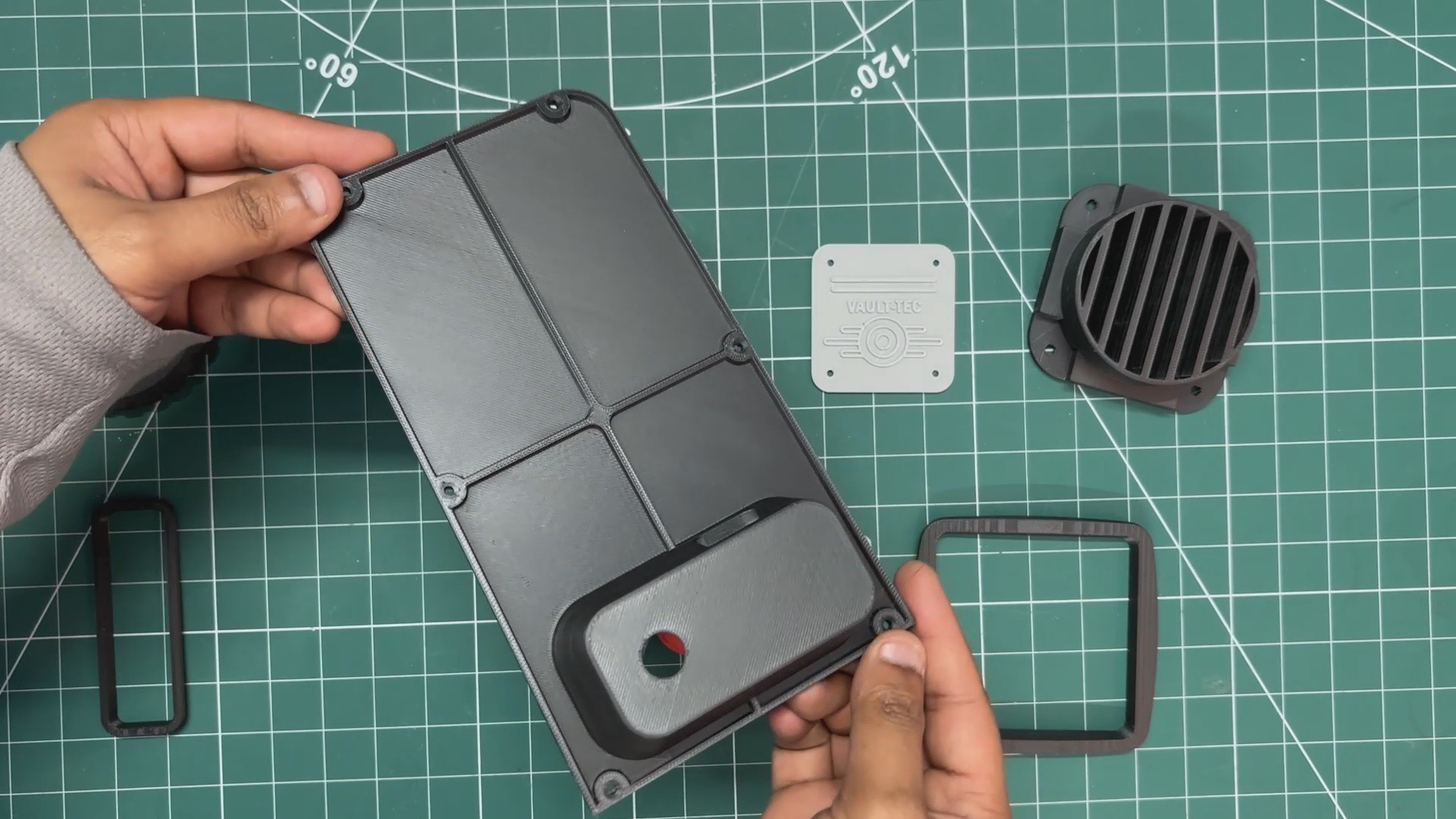
I exported all the component mesh files and started the 3D printing process by printing the main enclosure first. I used the Anycubic slicer for this. To add more strength, I increased the default infill from 15% to 25% and changed the infill type to gyroid. I went with a 0.16 mm layer height using normal infill in Snug style and printed the body using grey Hyper PLA. The color didn’t really matter here since the entire body was going to be painted later.
Using the same settings, I 3D printed the lid and both display frames in black Hyper PLA.
These were the main structural parts. The remaining pieces were greeble parts, which I modeled purely to improve the overall aesthetics.
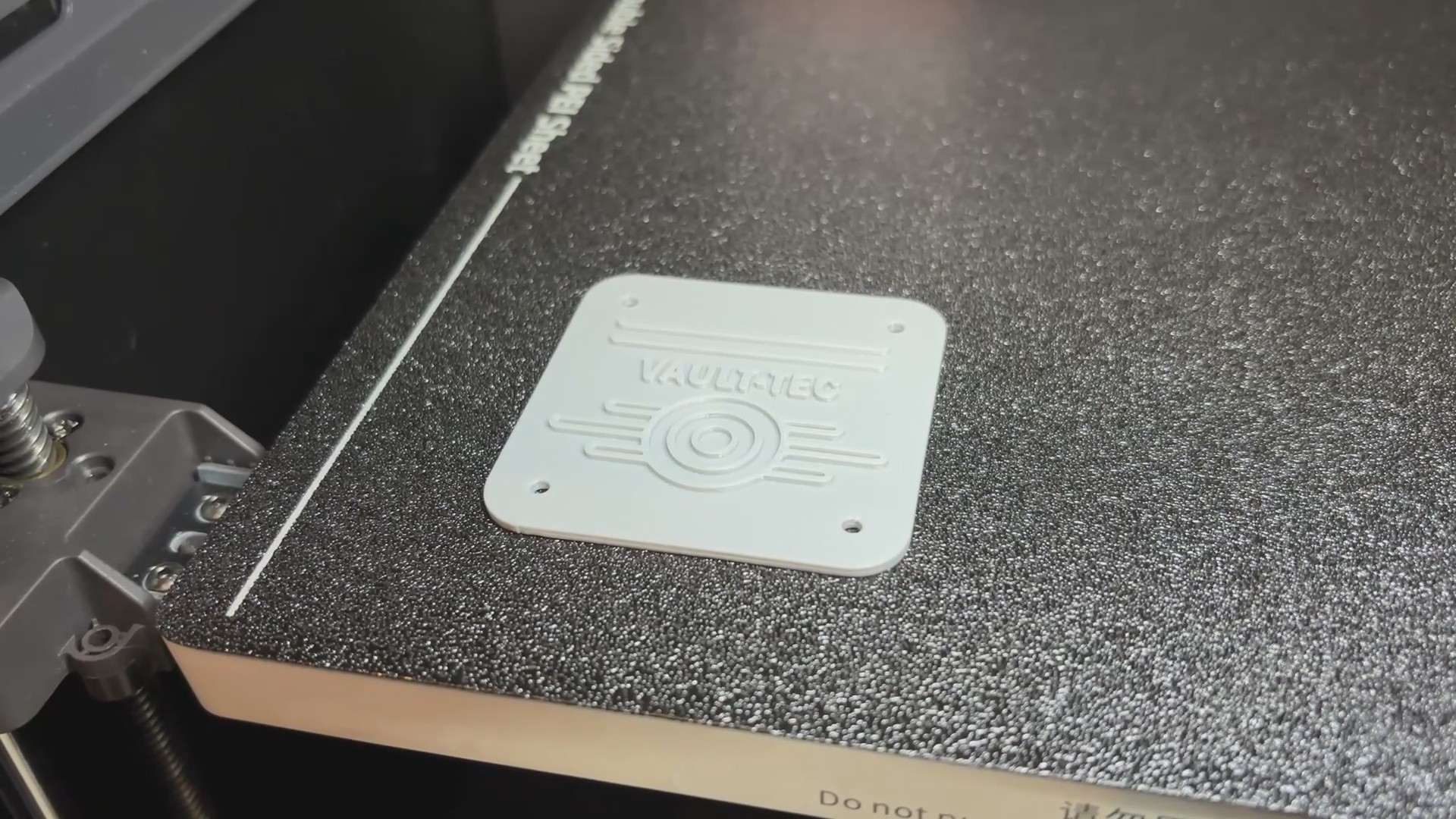
I started with the Fallout Vault-Tec logo for the front side, printing it using the same settings and grey Hyper PLA.
Next, I printed the RobCo logo and the Vault 101 logo using the same settings but with a slightly different approach. Both logos were printed in grey Hyper PLA, and halfway through the print, I paused it, swapped the grey filament with black Hyper PLA, and resumed printing.
This way, the lettering on both logos came out in black, which makes them look much bolder.
After that, I printed the front knob part using red PLA with the same settings as the previous prints.
The side knob was printed in black Hyper PLA, along with the speaker Grill.