Arnov Sharma
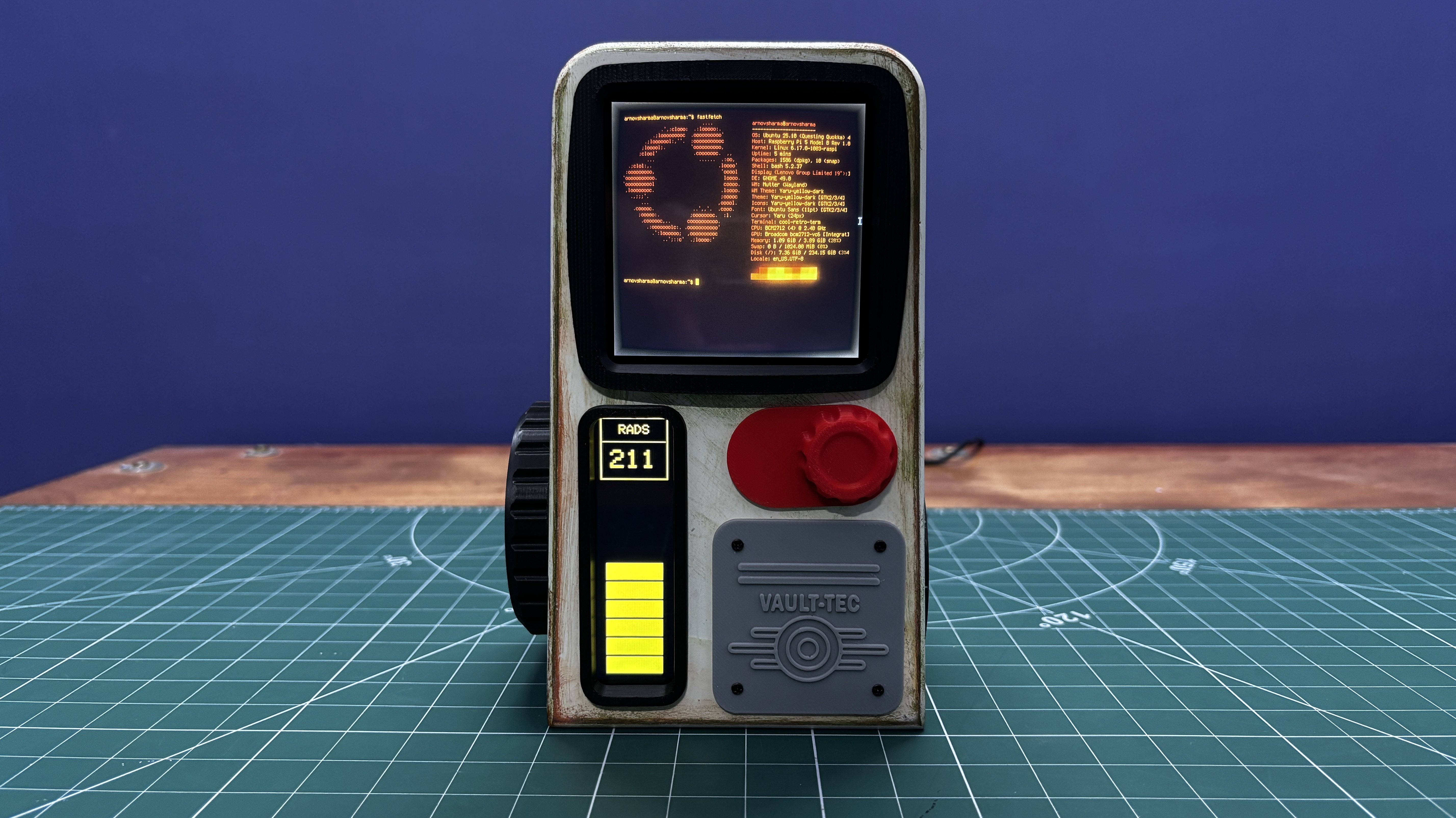
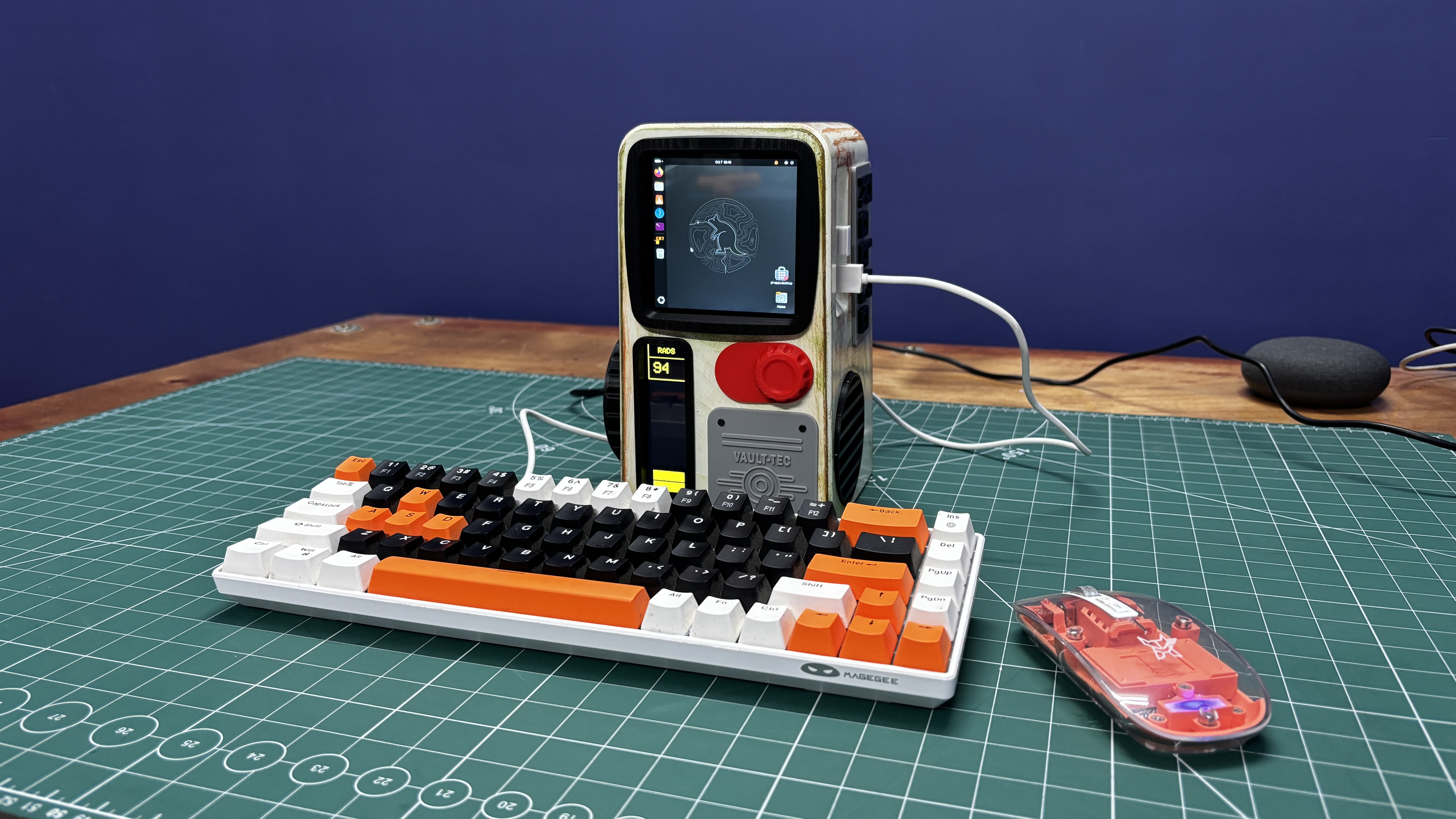
To make the build feel different and unique, I used a Square 4-inch waveshare HDMI display as the main screen, running a retro-styled terminal interface that closely resembles an actual Fallout terminal. This interface is an Ubuntu application called Cool-Retro-Term.
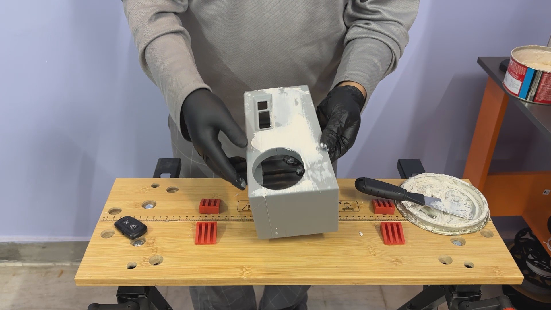
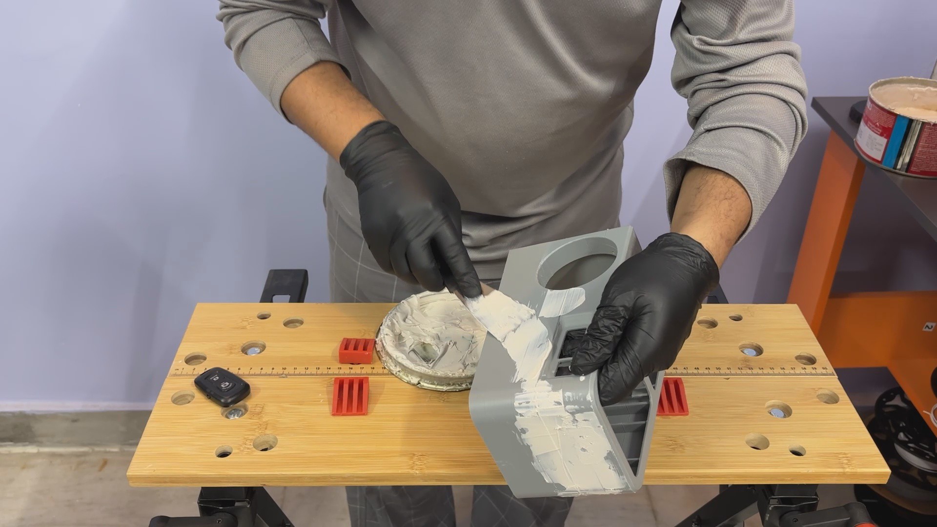
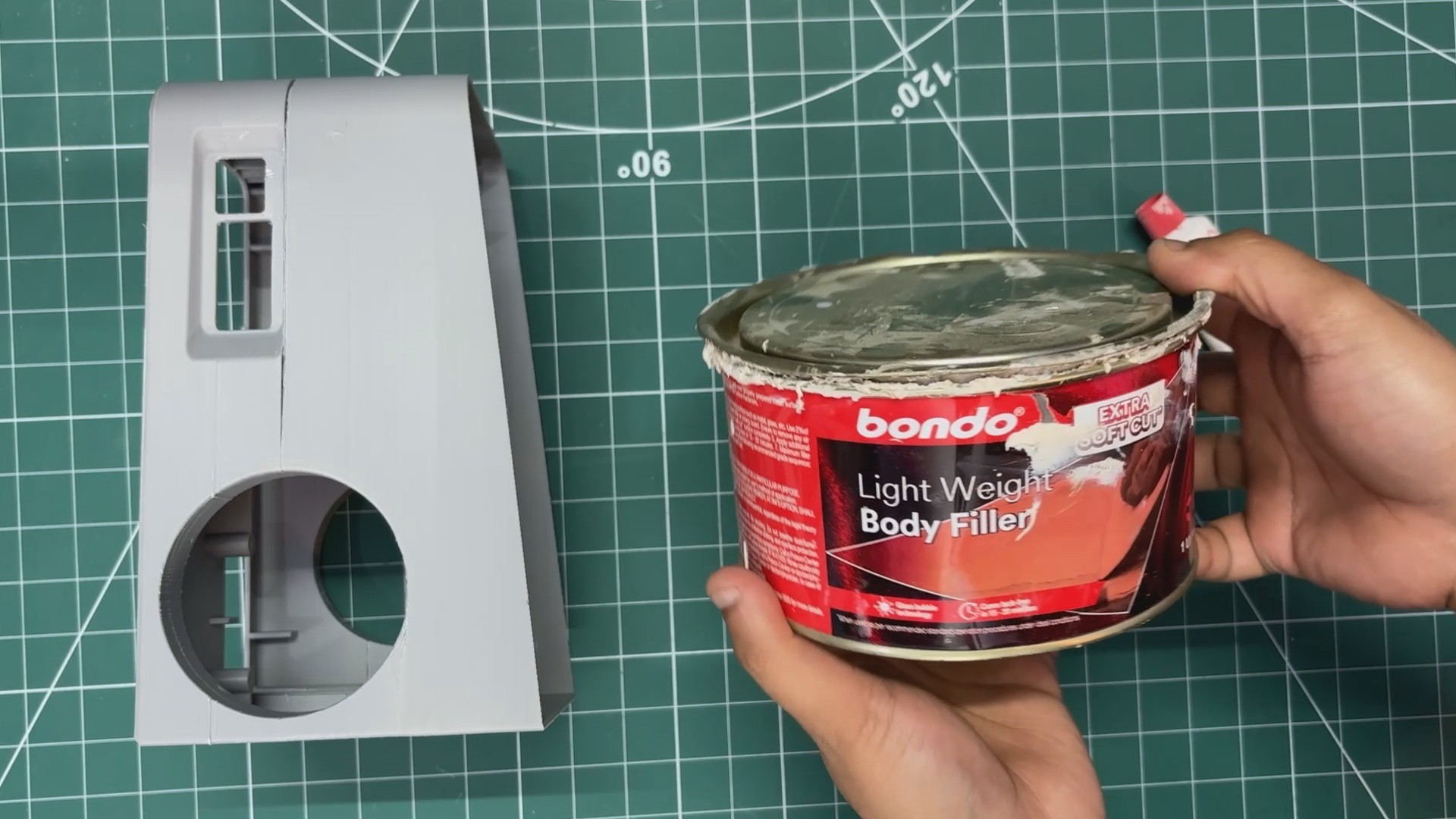
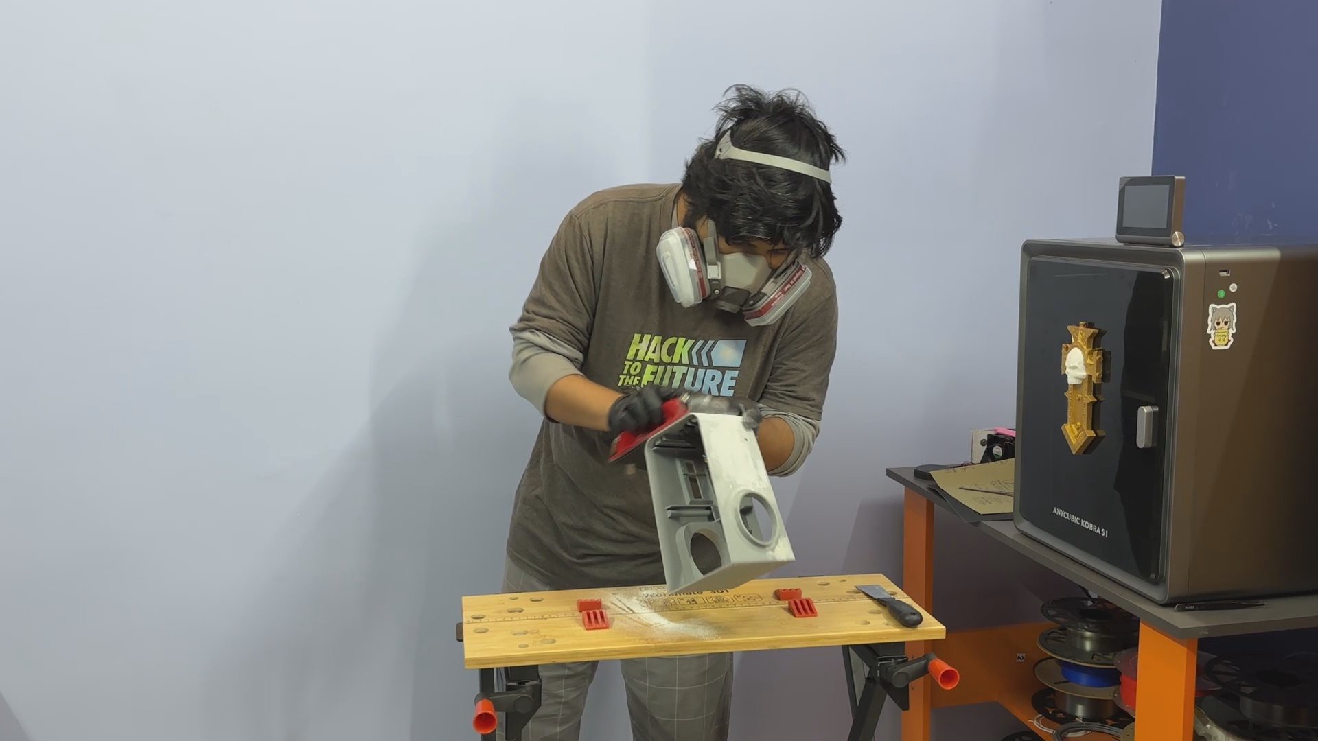
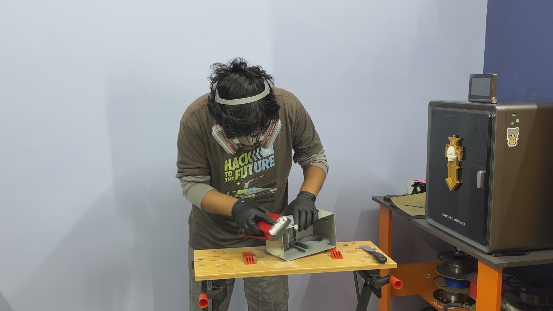
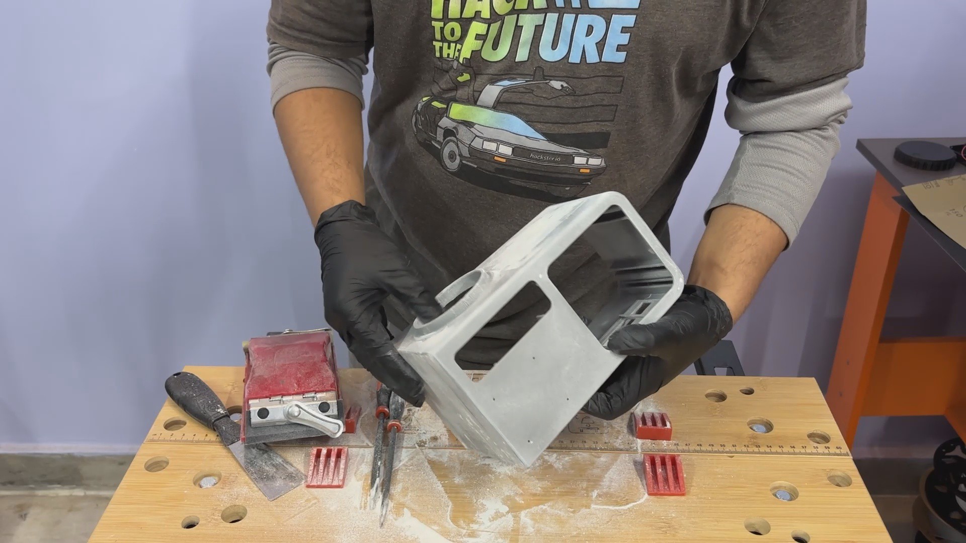
For the enclosure, I designed and 3D-printed the body, then painted and weathered it with artificial rust and mold patina. Small details such as knobs, logos, and surface greebles were added to make the terminal feel authentic, like a real piece of hardware from the Fallout world.
This article covers the complete build process of the Vault-Tec Air Terminal, from hardware and electronics to finishing and detailing.
So, let’s get started with the build.
MATERIALS REQUIRED
Following were the materials used in this project:
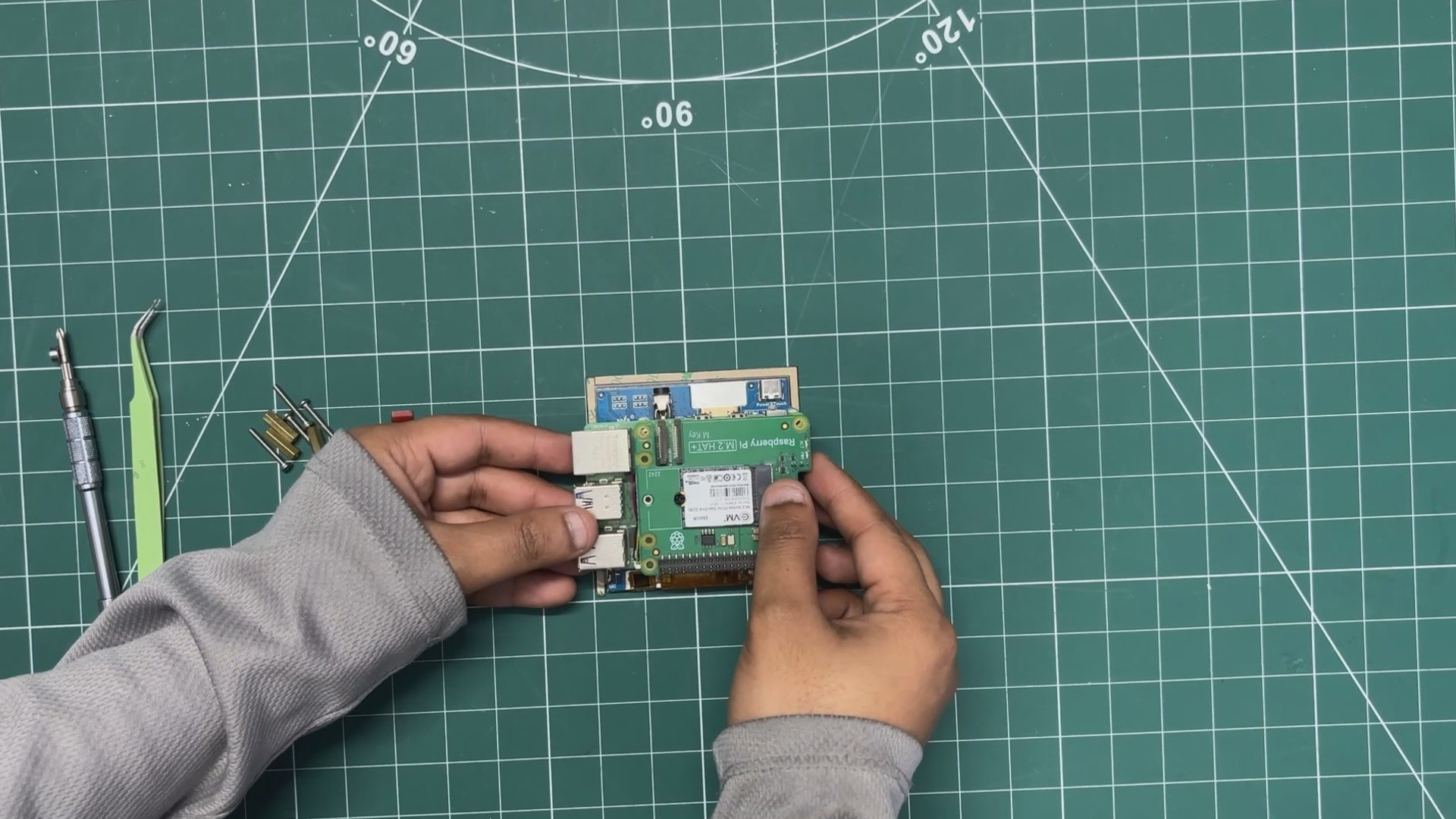
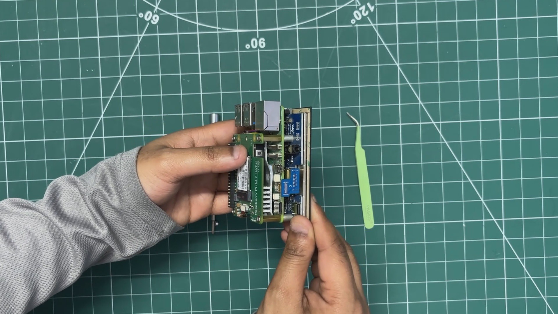
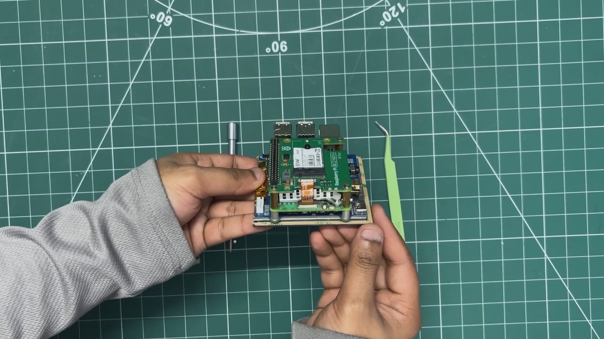
- Raspberry Pi 5
- M.2 PCIE Hat
- M.2 NVME SSD
- Waveshare 4-Inch HDMI Square Display
- TTGO T Display S3 Long
- 3D Printed parts
- DC STEP DOWN MODULE 5V 8A
- SGP40 Probe
- DC Barrel Jack
- Automotive Filler
- Red Oxide primer
- Sanding Equipment
- Beige Spray Paint
- Acrylic paint Brown and Green for Patina
- Acrylic Clear Coat Spray
INDOOR AIR QUALITY METER
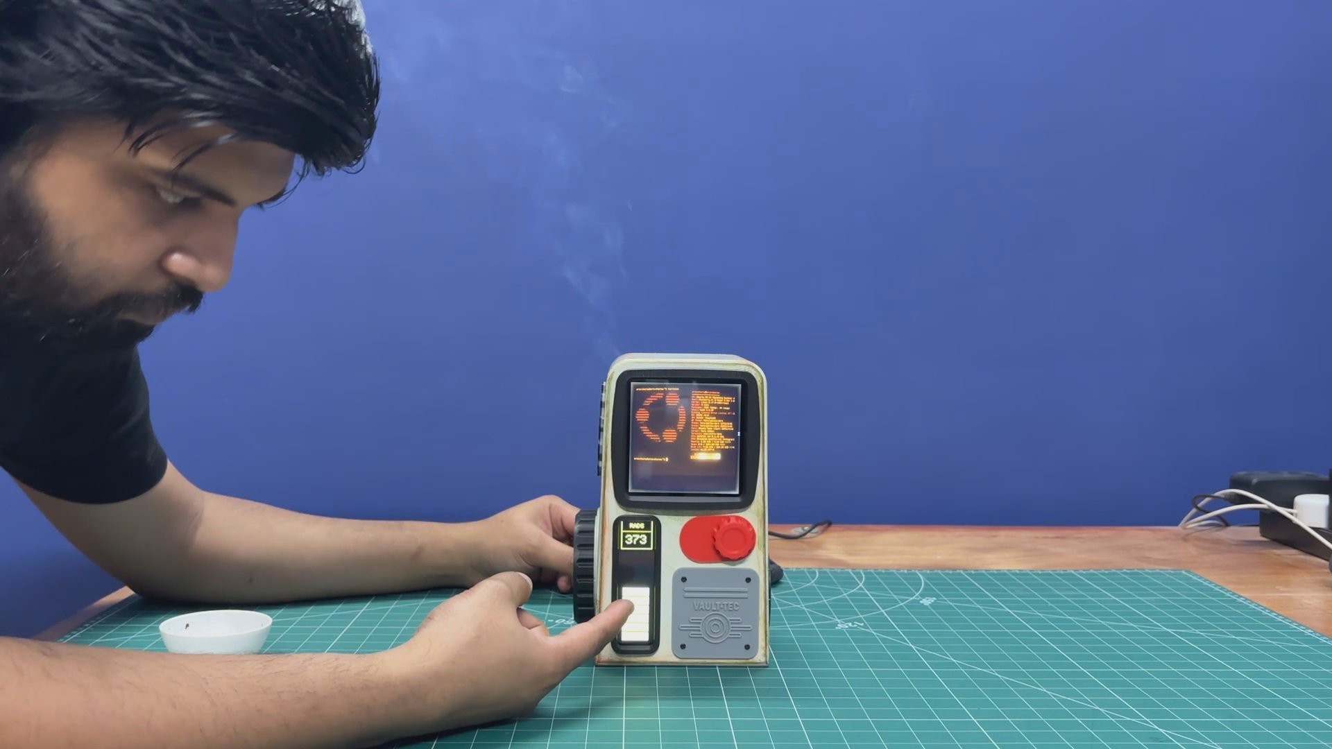

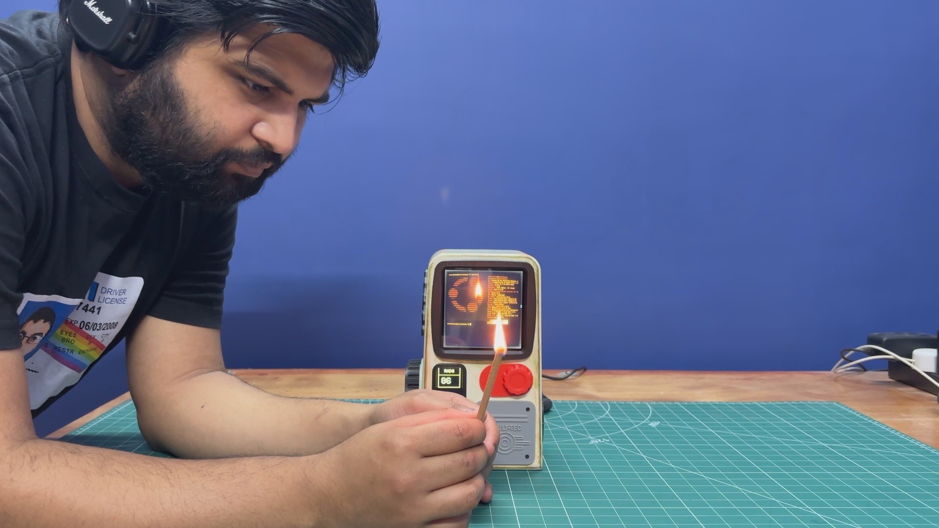
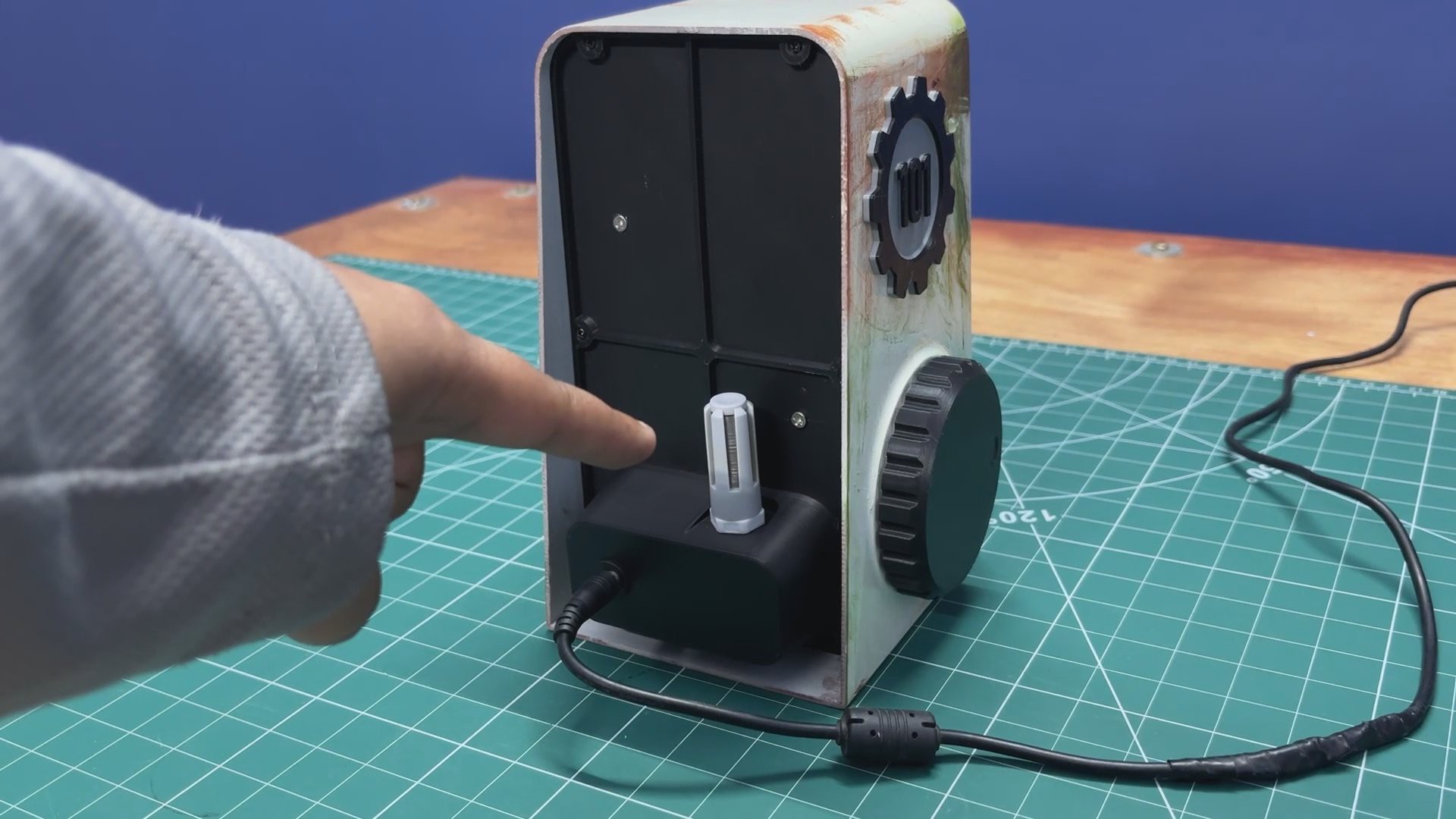
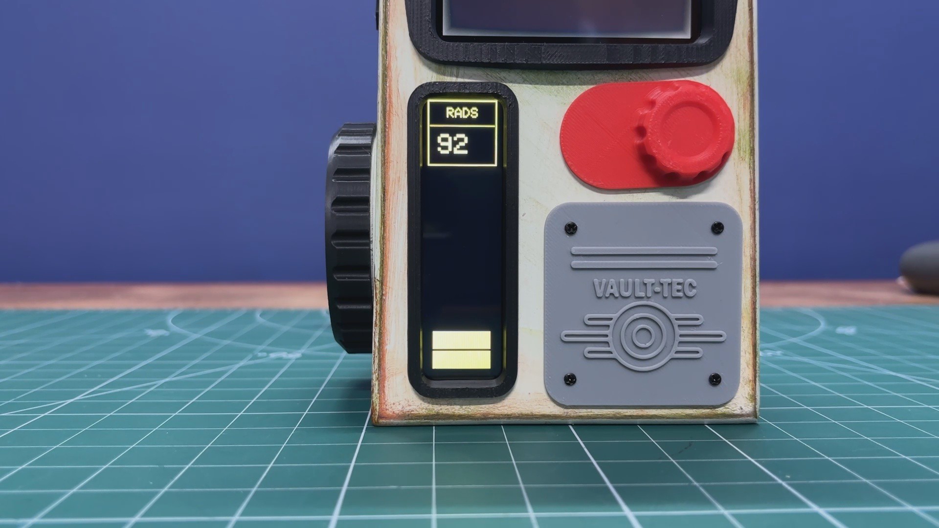
Here’s how the Vault-Tec Air Terminal’s air quality meter works. On the backside of the terminal, we added an SGP40 sensor housed inside a PG7 connector–based probe. The sensor continuously monitors the room’s air quality. Under normal conditions, my room’s air quality typically ranges between 50 and 100, which is displayed on the secondary screen.
The UI is designed to replicate a Fallout-style aesthetic, using bar indicators and text labeled RADS as an homage to the Fallout universe. To demonstrate changes in TVOC levels, I lit an incense stick and placed it near the sensor. This significantly increased the TVOC concentration, which could be seen immediately as higher numerical readings and corresponding increases in the on-screen bars.
FALLOUT TERMINAL


The Fallout franchise is a retro-futuristic, post-apocalyptic RPG universe that mixes 1950s sci-fi optimism with the harsh reality of nuclear fallout. My entry point into the series was Fallout: New Vegas, and it immediately set the standard for me with its writing, atmosphere, and freedom of choice.
One of the things that fascinated me most about Fallout is how differently technology evolved compared to our real world. In this universe, transistors were never widely adopted. Instead, technological progress continued to revolve around 1950s-era vacuum tube technology, even as society believed it had reached an advanced future. This single divergence shaped nearly every aspect of the Fallout world.
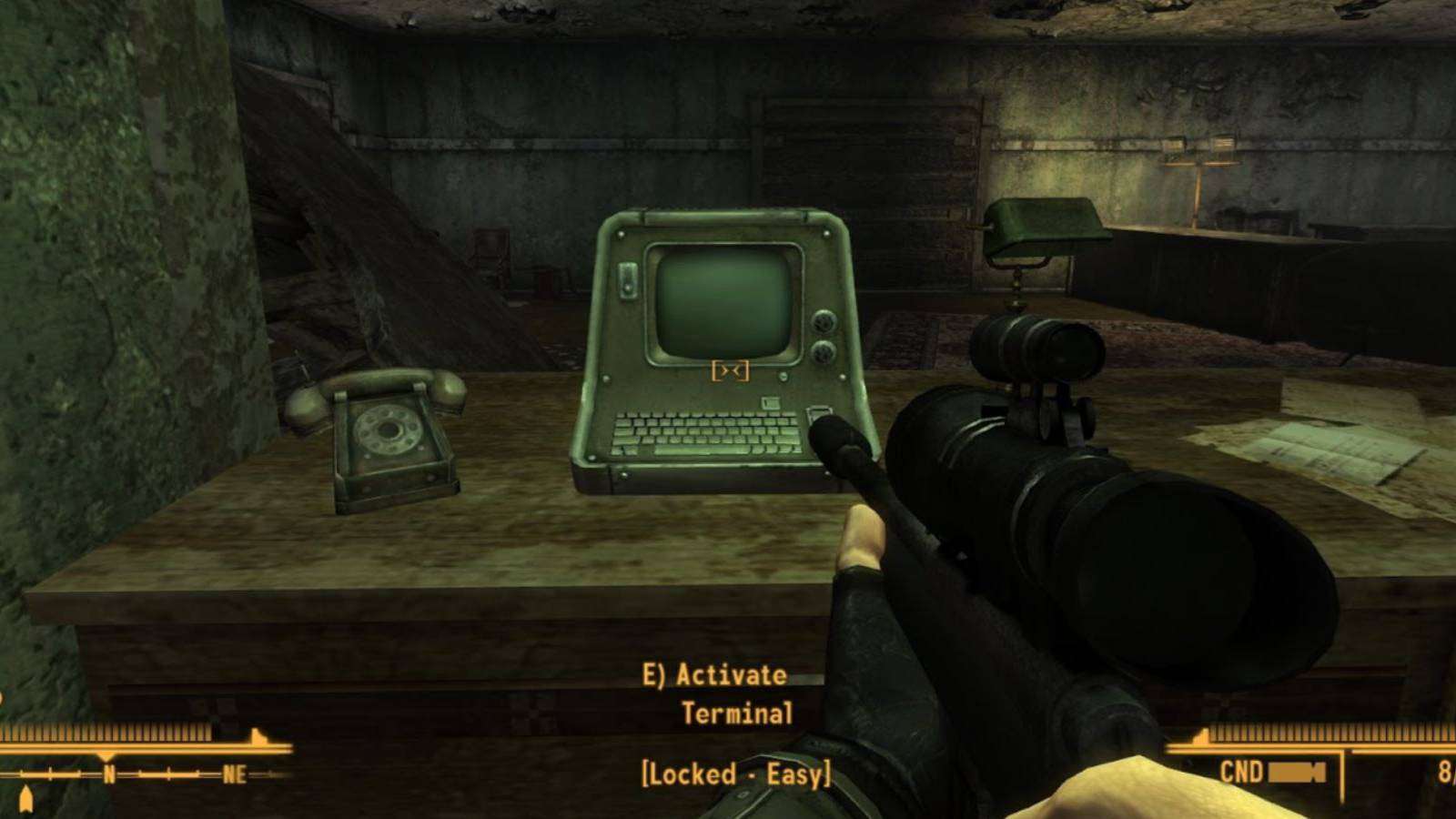
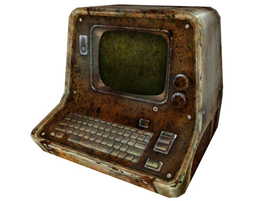
This is especially visible in Fallout’s computer terminals. They were never designed to be comfortable or visually appealing. Instead, they are purely functional machines, built for control, logging, and authorization. Interacting with them feels deliberate, using a physical keyboard to unlock doors, control turrets, access security systems, or read archived corporate and government communications.
Most of these terminals were developed by RobCo Industries, founded by Robert House, who also plays a major antagonistic role in New Vegas.
Physically, Fallout terminals feel imposing. Thick metal casings, exposed vents, mechanical switches and knobs, and the constant glow and flicker of CRT screens emphasize their electro-mechanical nature. They feel more like industrial control panels than consumer electronics. Even centuries after the nuclear war, many of these terminals still function, which suggests that while vacuum tube technology is inefficient and power-hungry, it is also incredibly resilient.
For me, these terminals are more than just gameplay mechanics. They act as storytelling devices, preserving fragments of the pre-war world. Reading emails, error logs, and security notices reveals corporate greed, government paranoia, and small, human moments frozen in time, often making the terminals feel like quiet witnesses to a...
Read more »