 pchala
Why Build This? (My Motivation)
There are already some fantastic open-source espresso mods out there (like the Gaggiuino or GaggiMate), so why start from scratch? My motivation boils down to three main things: a different design philosophy, a deep dive into embedded Rust, and the pursuit of coffee science.
1. The UI Philosophy: No Screens, Just Coffee Most existing mods rely on touchscreens. My goal is absolute minimalism. In the morning, before I’ve had my coffee, I don't want to navigate menus on a tiny screen with my big fingers. I want tactile buttons and LEDs. I can just press a single button, and the machine executes my perfect default profile. For the heavy lifting (creating profiles, viewing live telemetry charts, tuning PID), the RP2040 hosts a built-in Web Server. I, or any guests, can just pull out a smartphone browser to control the machine—no app installation required.
2. The Tech Stack: Learning Async Rust The absolute main driver for this project is educational. I wanted to deeply learn embedded Rust. By utilizing the Embassy framework, I am getting hands-on experience with Async concepts on microcontrollers. It has been a revelation; designing the system as a collection of decoupled, asynchronous tasks makes the code incredibly clean, easy to modify, and safe.
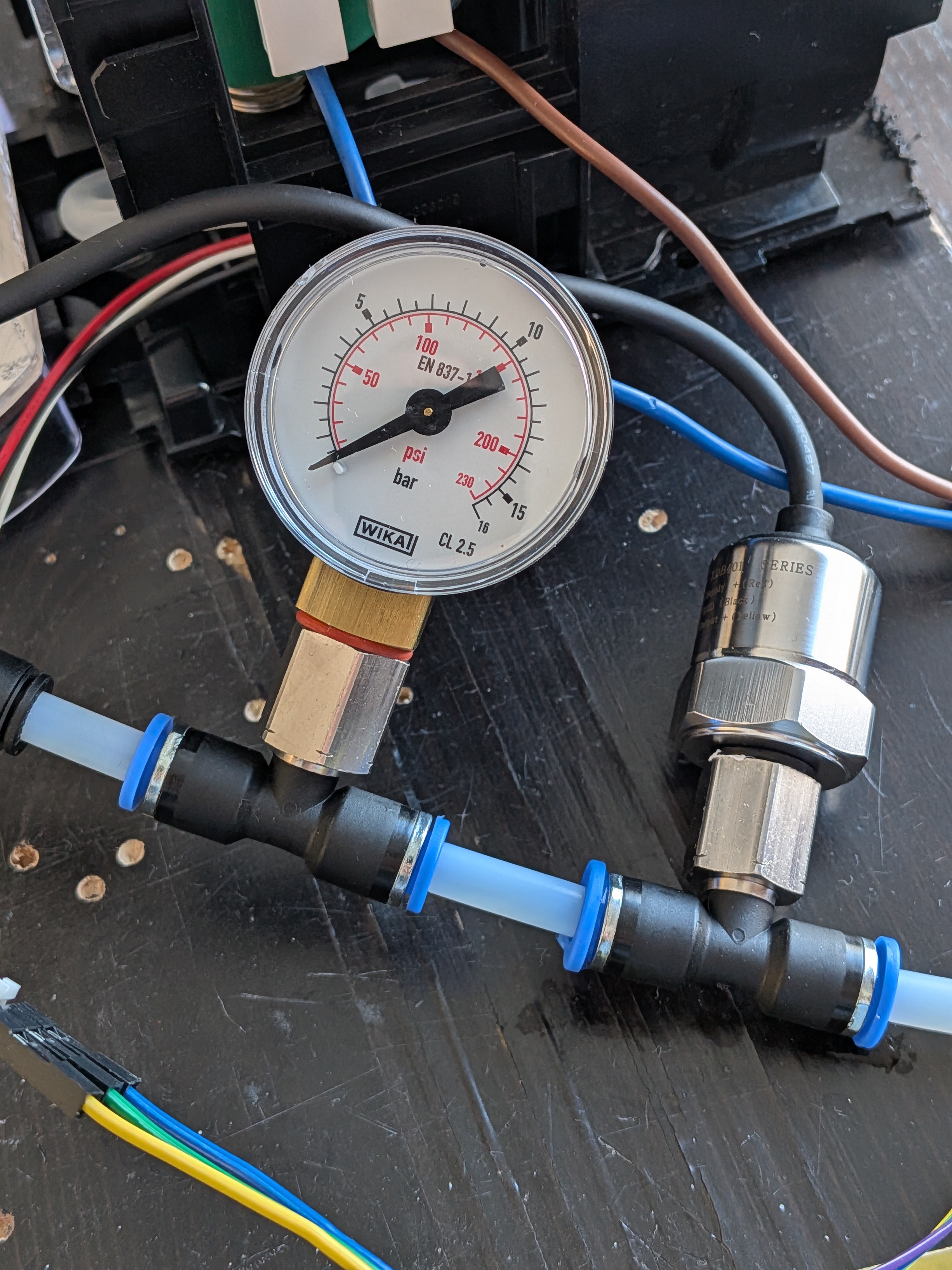
3. Industrial Control & Hardware Hacking I wanted to refresh my knowledge of industrial control loops while learning the actual physical science of coffee extraction. To handle the vibratory pump and sensors, I am writing some assembly code to run in parallel on the RP2040’s PIO (Programmable I/O) hardware blocks. Offloading microsecond-accurate phase control and flow-meter pulse timing to the PIO leaves the main async Rust OS completely free to handle the logic, math and the web server.
Ultimately, this project is the perfect intersection of my desire to learn cutting-edge embedded software techniques, industrial hardware control, and how to pull a god-tier shot of espresso.
 Saabman
 andyknitt
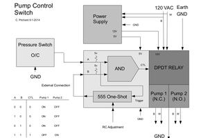
 C. Prichard