Sagar 001
I have used too many current and power measurement meters in the past. And I always want to build a better version of the previous one. Most of my work kept revolving around making measuring and test equipment, in the hope of someday creating a revolution in the testing world. The most common method is using a shunt resistor, but it introduces voltage drop and power loss in the circuit.
I built a DC ammeter using a toroidal ferrite core and a Hall Effect sensor (WSH130NL). The idea is, when current flows through a wire wound around a toroidal core, it creates a magnetic field inside the core. For AC measurements we can just use a secondary winding and get a pretty good step down transformer producing an effective voltage which can be converted into current values. But with a DC steady signal we have to measure the magnetic flux in a different manner.
By cutting a gap in the toroidal core and placing a Hall Effect sensor in that gap. With this we can measure the magnetic flux density, which is directly proportional to the current flowing through the windings. I know this is the same thing which is used in clamp meters and that’s how the idea comes to my mind. Overall now with this approach we get an isolated, non-invasive current measurement. And by choosing the right number of windings, you can adjust the sensitivity and resolution of your ammeter to suit your needs. The same can be converted later with the help of a PCB provided by JLCPCB. As I got my MCU dev board fabricated from there in a $2 price.
How Does It Work?
The working principle is based on Ampere's Law and the Hall Effect. Let me break it down step by step. When current passes through a conductor wound around a toroidal ferrite core, it generates a magnetic field inside the core. The key takeaway here is that magnetic flux density (Tesla) is directly proportional to both number of turns and current. So if we keep N fixed, the magnetic flux density becomes a linear function of the current.
The ferrite has a very high permeability, which means the magnetic field is mostly confined inside the core. To measure it, we need to introduce a small air gap in the toroidal core. When we cut a gap in the core, the magnetic flux that was flowing through the ferrite now has to cross this air gap. By placing a Hall Effect sensor right in this air gap, the sensor sits in the path of the magnetic flux. The Hall Effect sensor generates a voltage proportional to the magnetic field passing through it.
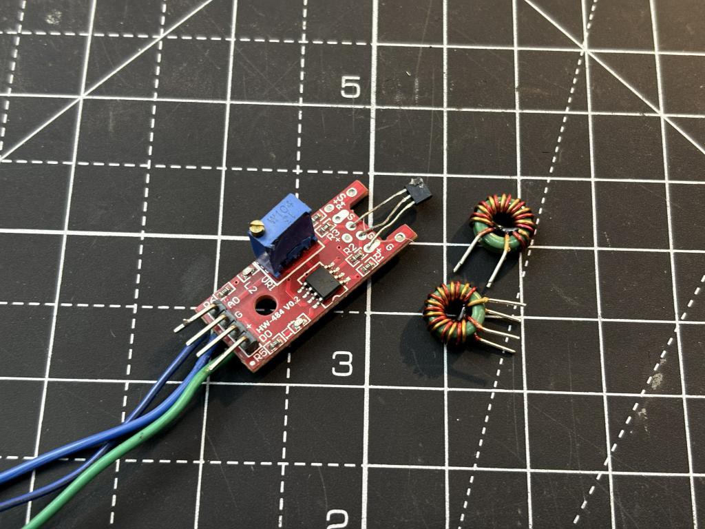
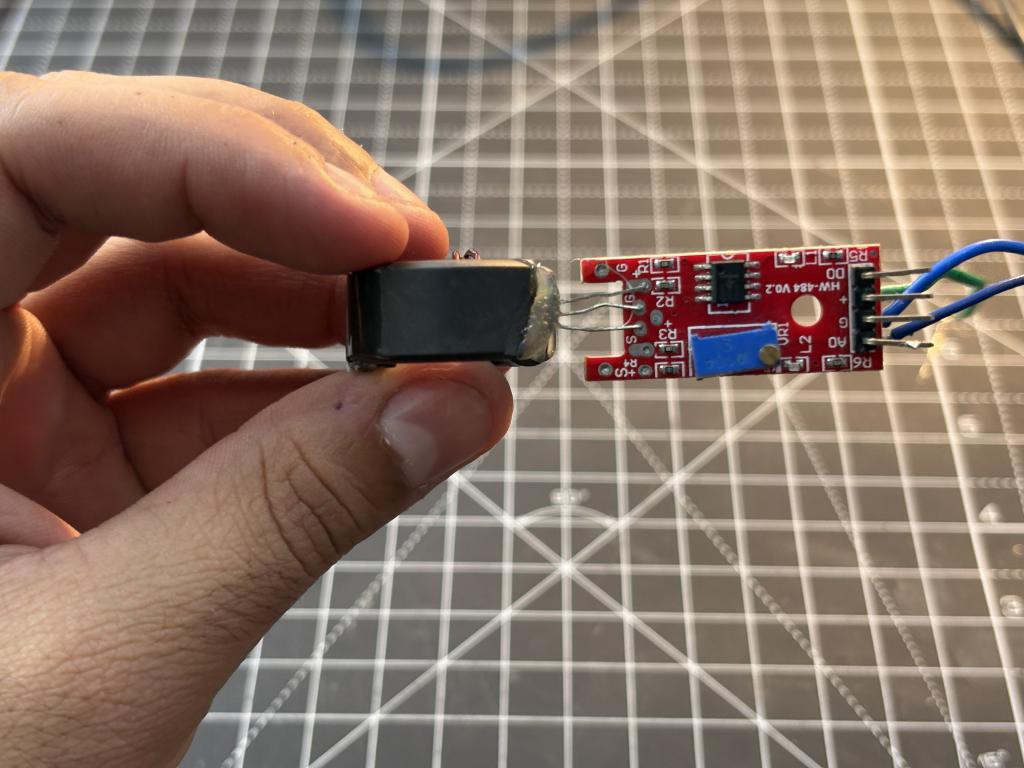
WSH130NL Sensor:
Better the sensor more linear will be the output with good resolution. I am using this breadkout module board which is available in the same price of the sensor.
- Wide supply voltage range (2.4V-26V)
- Temperature compensation
- Small TO-92S package
- Fast response - sub-microsecond switching times
- Low power consumption - only 2mA typical
The sensor includes on-chip temperature compensation, so as temperature changes can shift the magnetic characteristics of both the ferrite core and the sensor itself.
Components Required
- WSH130NL Hall Effect Sensor
- Toroidal Ferrite Core
- Enamelled Copper Wire
- 10K Ohm Resistor
- 0.1uF Capacitor
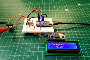
- Arduino Uno/Nano (To get digital readings)
- 16x2 LCD Display I2C (To get digital readings)
- Breadboard & Jumper Wires
- Connecting Wires
- Hacksaw / Dremel
- Sandpaper
- Super Glue / Epoxy
Building the DC Ammeter - Step by Step
The toroidal ferrite core is the heart of this ammeter. You can salvage one from an old power supply, a common-mode choke, or buy one online. The size doesn't matter too much, but a larger core gives you more room to wind wires.
Cutting the Air Gap:
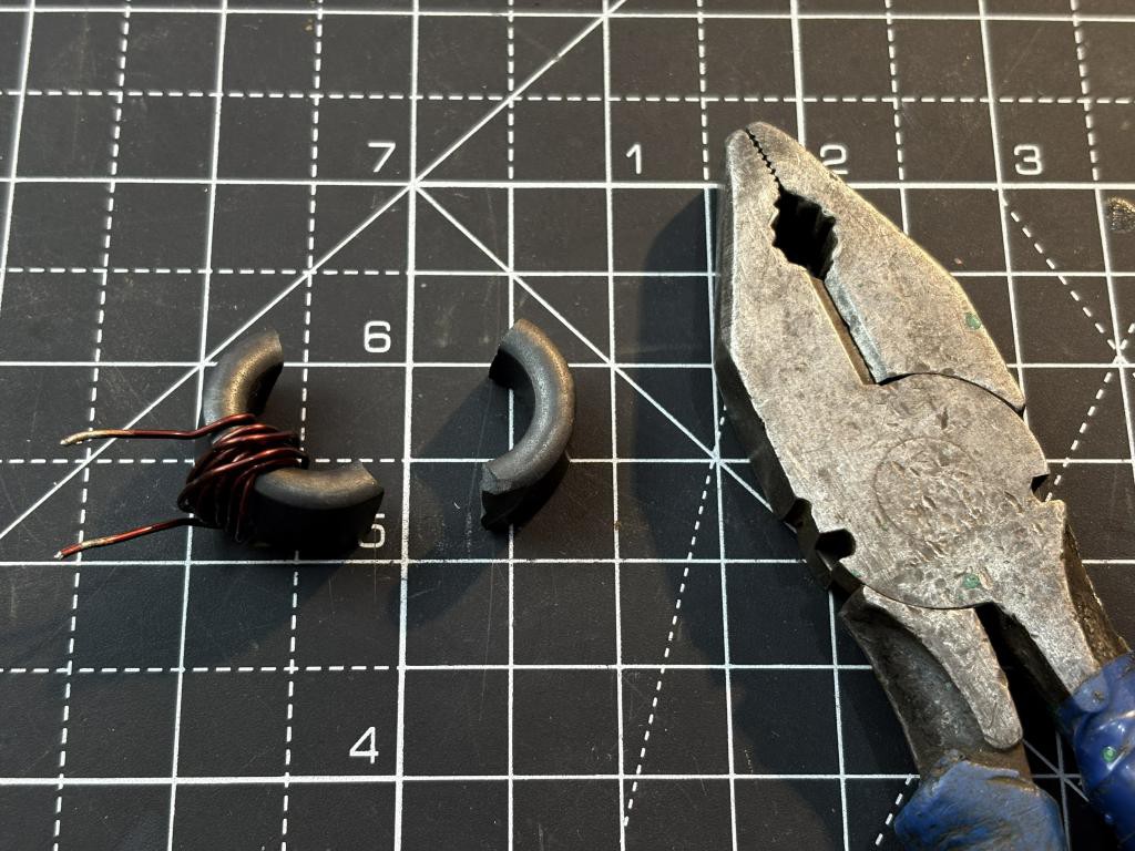
This is the most critical and tricky step. We need to cut a small gap in the toroid where the Hall sensor will sit. Let me tell you what I did, I just took a plier and broke it into two pieces. This may be non ideal but I can later glue the parts to fix it. You can use a Dremel with a thin cutting disc or a fine hacksaw blade. Cut slowly and steadily. After...
Read more »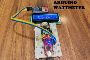
 Lithium ION