 Robert Gawron
I'm testing the model of my analog frontend against requirements in LTspice, and in this post, I will share an LTspice hack I came up with for the problems below:
- There are many configuration analysis models in LTspice that I need. If I kept everything in one file, I would need to comment/uncomment what I need for each simulation. This is annoying.
- Depending on the tests, I need different models of the SiPM. Again, I could connect/disconnect what I need, but this is annoying and error-prone.
- If I split these into different LTspice simulations and then change the analog frontend (for example, a resistor value), I need to manually update every single file to keep them coherent.
The solution is to create a symbol for the part under test (the analog frontend) and reuse it in all my LTspice test benches. Since the symbol lives in two files (.asy and .sub), they just need to be regenerated from the main analog frontend model, and then all test models can use them.
It looks simple and reasonable, but it didn't work well in LTspice at first..
I made the tutorial below for myself and others on how to do it
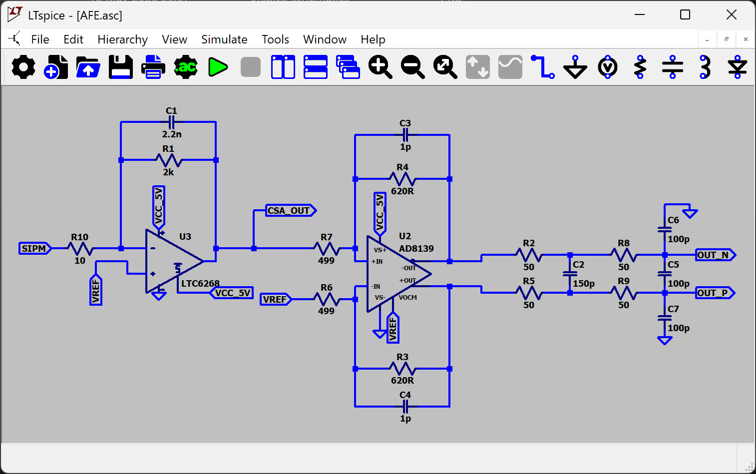
Step 1: pure model (.asc file)
We create the model of the component under test (as an .asc file) without:
- Any power sources
- Any sensors
- Any LTspice directives
Just a pure circuit with no external components.
Add labels to its inputs, outputs, and power nodes (GND doesn't need one). Anything that needs to be connected in the test bench models must be labeled; otherwise, those nets won't be visible in the subcircuit.
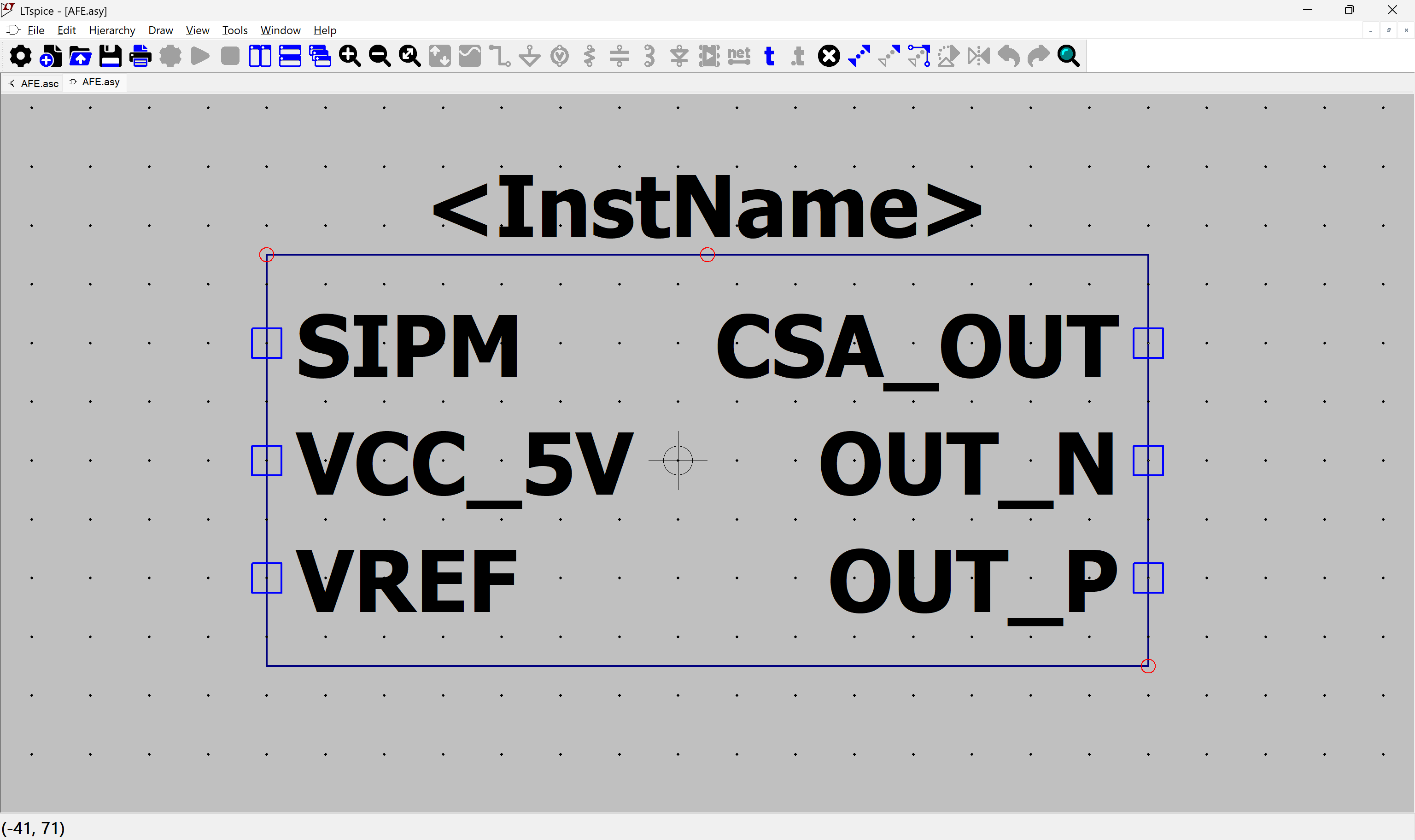
Step 2: symbol of the model (.asy file)
Now we create the .asy file (representing how the component looks on the schematic and defining its pin names and numbers):
Click "Hierarchy" -> "Create a New Symbol from this Schematic", and click Yes.
Now we have our symbol. Note that it is filled with a background color (grey).
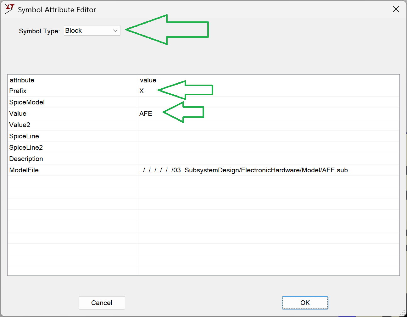
Go to "Attributes" -> "Edit Attributes".
The Prefix must be "X". This is important because it tells LTspice to treat the component as a subcircuit (otherwise, it won't work).
.asy file of the tested model should be in the same folder as its .asc file.
Step 3: behavioural model (.sub file)
We need a .sub file (which describes how the circuit behaves, this is the real model). The automatic generation never worked well for me, so I made a workaround.
Open the .asy file in a text editor and find the entries like these:
SYMATTR Value AFE

...

PINATTR PinName SIPM
PINATTR SpiceOrder 1
PIN -112 -32 LEFT 8
PINATTR PinName VCC_5V
PINATTR SpiceOrder 2
PIN -112 0 LEFT 8
PINATTR PinName VREF
We are interested in the names found after PinName, they will be different depending on what is on the model (for me they are as above).
Next, create the unpopulated .sub file. The subcircuit file for the tested model should be in the same folder as the .asc and .asy files. They should all have the same filename, differing only by their extensions.
Using a text editor, place the following dummy content into the .sub file:
.SUBCKT AFE SIPM VCC_5V VREF CSA_OUT OUT_N OUT_P
** CIRCUIT_BODY_START **
** CIRCUIT_BODY_END **
.ENDS AFE
The line starting with .SUBCKT is important, based on your specific model:
- First element: This is the name of your model (this must match the SYMATTR Value from the .asy file).
- Then goes the PINS, list the pins exactly as they appeared in the .asy file (PINATTR PinName). The order matters!
Place the Python script in the same folder as your files and run it.
import re
from pathlib import Path


def extract_net_body(net_path: Path) -> str:
    """
    Extract all lines from .net except .end (case insensitive).
    """
    lines = net_path.read_text(encoding="utf-8").splitlines()

    filtered = []
    for line in lines:
        stripped = line.strip().lower()
        if stripped == ".end":
            continue
        filtered.append(line)

    return "\n".join(filtered)


def replace_subckt_body(sub_path: Path, new_body: str) -> None:
    """
    Replace content between CIRCUIT_BODY_START and CIRCUIT_BODY_END
    with new_body.
    """

    content = sub_path.read_text(encoding="utf-8")

    pattern = re.compile(
        r"(\*\* CIRCUIT_BODY_START \*\*).*?(\*\* CIRCUIT_BODY_END \*\*)",
        re.DOTALL
    )

    replacement = (
        "** CIRCUIT_BODY_START **\n\n"
        + new_body.strip()
        + "\n\n** CIRCUIT_BODY_END **"
    )

    # Use lambda to prevent re.sub from interpreting backslashes
    new_content = re.sub(pattern, lambda m: replacement, content)

    sub_path.write_text(new_content, encoding="utf-8")

def net_to_sub(net_file, sub_file):
    net_path = Path(net_file)
    sub_path = Path(sub_file)

    if not net_path.exists():
        raise FileNotFoundError(f".net file not found: {net_file}")
    if not sub_path.exists():
        raise FileNotFoundError(f".sub file not found: {sub_file}")

    print("Extracting .net body...")
    net_body = extract_net_body(net_path)

    print("Updating .sub file...")
    replace_subckt_body(sub_path, net_body)

    print("Subcircuit updated successfully.")


# =============================
# Example usage
# =============================
if __name__ == "__main__":
    net_to_sub(
        r"AFE.net",
        r"AFE.sub"
    )
Now we have both the .asy and .sub files. As long as there is no change to the pins (which shouldn't happen often), we only need to run "View" -> "Spice Netlist" and launch the Python script whenever you modify the circuit. All your test bench models will now automatically use the updated version of the tested model.
Step 4: How to use the component in other models
This part is a bit messy: the .asy file needs to be copied into the same folder as the test bench models (I haven't found a way to reference it via a relative path yet).
However, the .sub file can be referenced using an LTspice directive:
spice
.include "../path_to_file/AFE.sub"
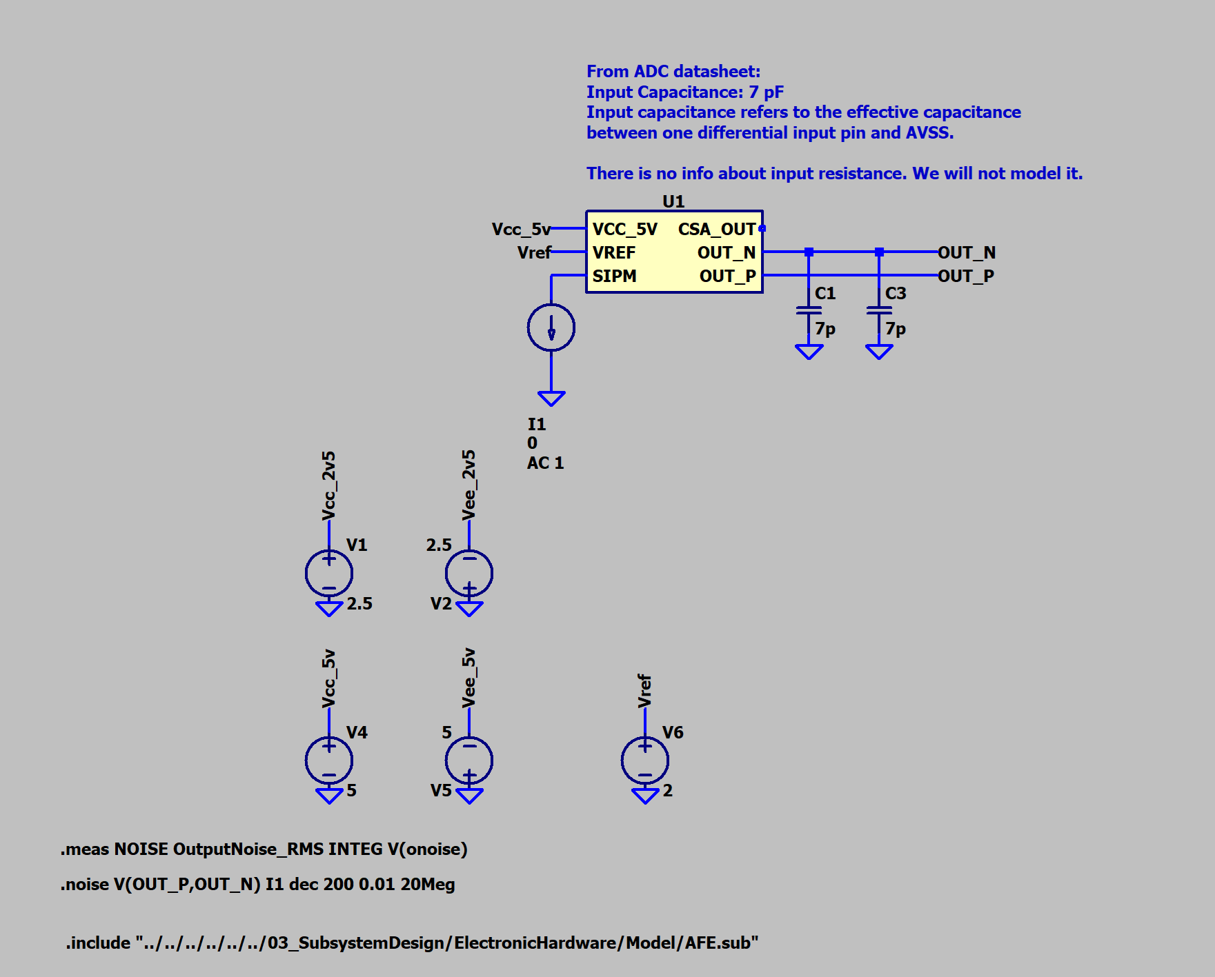
Here is how it looks in practice:
Link to where it is on Github:
Discussions
Become a Hackaday.io Member
Create an account to leave a comment. Already have an account? Log In.