 Robert Gawron
Choosing detector elements
This project will be much more expensive than what I was thinking - scintillator crystals and PIN diodes are expensive! I've found a shop online that has scintillator crystals, and it seems to me that this one will be good:
- Sodium-doped cesium iodide crystal (CsI(Na)), 10x10x10mm .. $290.00 + tax + probably duty because they are in China and I'm in Europe. EDIT: just use cheapest NaTI that is sealed (because it's hygroscopic) https://www.epic-scintillator.com/NaI-crystal-scintillator/NaI-crystal-30x24mm?sort=p.price&order=ASC or maybe use cheapest plastic one to check if device works and then switch to better ones: https://www.epic-scintillator.com/Plastic-scintillator?product_id=912&sort=p.price&order=ASC EDIT2: this site is cheaper: https://www.ost-photonics.com/product/diameter-1-inch-x-1-inch-naitl-scintillator/
- S3590-08 PIN photodiode .. 111 euro + tax. EDIT: this is better/cheapper: https://eu.mouser.com/ProductDetail/onsemi/MICROFC-60035-SMT-TR1?qs=byeeYqUIh0MxSRIaBcfS6g%3D%3D or https://eu.mouser.com/ProductDetail/ams-OSRAM/SFH-2240-A01?qs=T%252BzbugeAwjjFSBEKp8QF2A%3D%3D choose scintillator first, it's usable shape wavelength peak will dictate sensor choose.
Hopefully, the frontend is the most pricey part, I think.
Choosing sensor biasing
The PIN diode can be biased either negatively (pulses will be positive, meaning signal peaks when a particle is detected will be higher than the background) or positively (peaks will be lower). Negative biasing seems better, so I will stick to it.
The S3590-08 can withstand 100V of reverse voltage, so I plan to bias it with -70V - that should be good enough and it gives margins (I want to be extra safe since it costs money!).
The easiest and cleanest way, at least for a prototype, is to just use 12V batteries in series. I've already used this when I was building a semiconductor radioactivity detector (which is a much more simplified version of the gamma spectrometer being designed here). The problem with batteries is that they lose voltage over time (although the PIN diode takes almost no current) and they take up a lot of space on the PCB/device.
I was thinking about a DC/DC converter to produce the needed -70V, but then I would need a coil or a transformer in it, and I don't want to mess up the small signal from the diode with EMI interference from a coil. Maybe that's not a problem at all; I don't know, as I haven't built such a thing before.
I then moved toward a voltage multiplier and designed a Dickson charge pump using LTspice, which at least in theory would give me the needed -70V from a usual 5V. Here is the circuit and simulation:
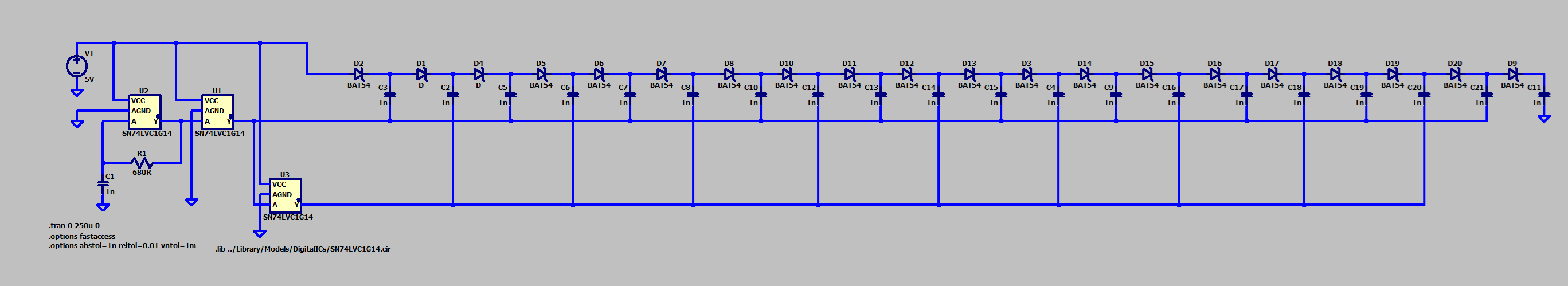
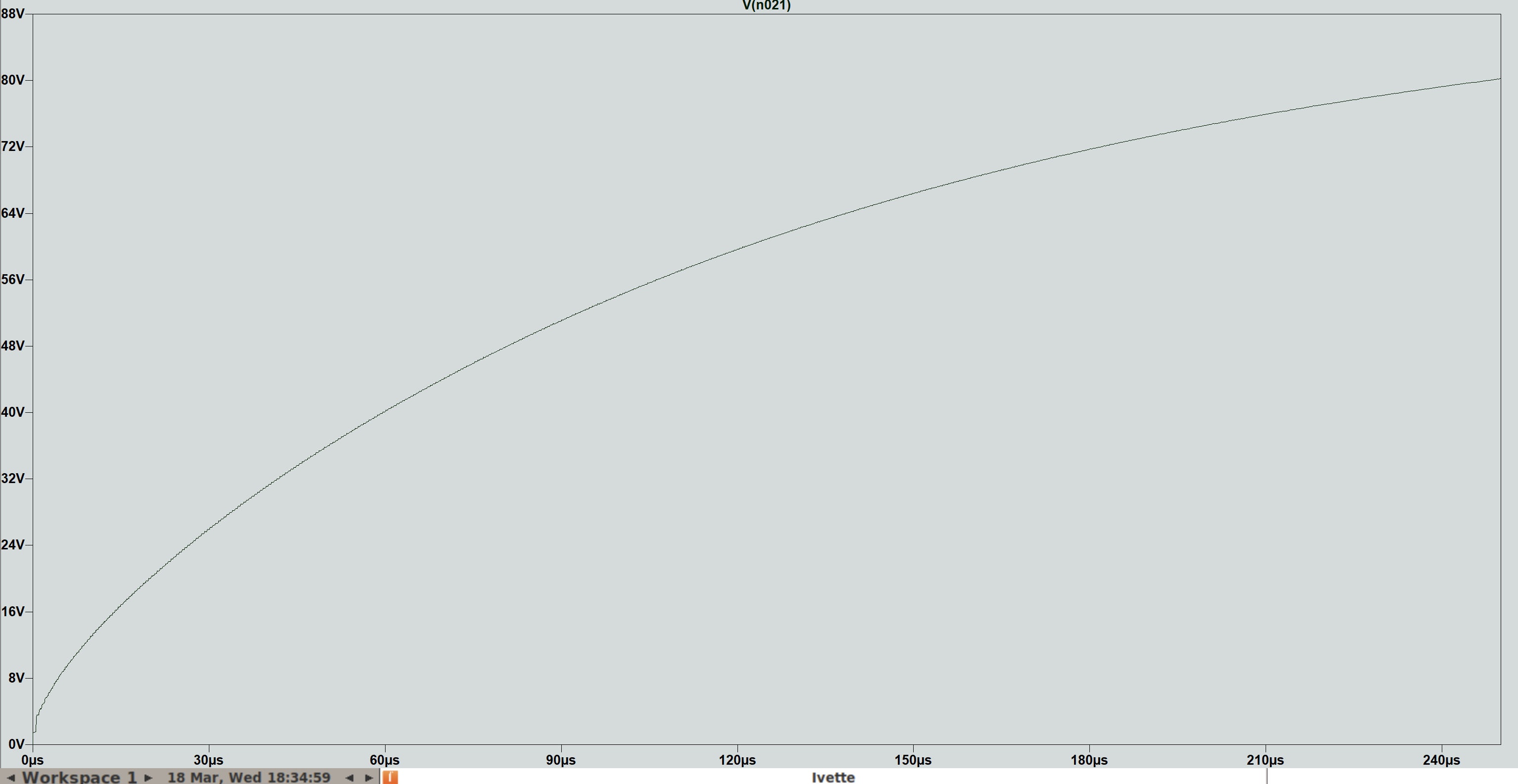
Will this circuit work in real conditions with all the parasitic capacitances, resistances, etc? I don't know, so I will put space on the PCB for both batteries in series and this charge pump. If the pump works, great, if not, I will use batteries in the first prototype.
Discussions
Become a Hackaday.io Member
Create an account to leave a comment. Already have an account? Log In.