Close
0%
0%

RCKid

The first truly personal device for kids — designed to grow with them from drawing sprites to writing C++

Similar projects worth following
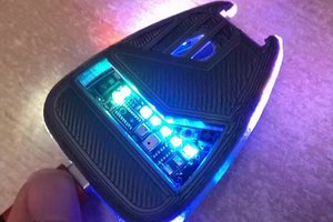
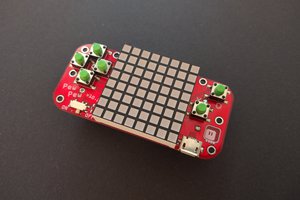
Open‑source handheld console designed for young creators. It’s built to be the first piece of technology that feels truly personal to a child — not just a screen to consume, but a tool to imagine, build, and share. Supports kids in everyday tools like a clock, alarm, piggy bank, contacts, or music player. This balance of fun and function turns RCKid into a trusted companion, introducing kids to digital literacy, technology, and STEM skills in a way that grows with them.

Starting at age 5, kids can design sprites, tiles, and music inside native games, learning problem‑solving naturally through play. As they grow, RCKid will provide more and more complex ways of control (visual blocks, scratch-like blocks, C++, Full C++ SDK).

A defining feature is RCKid’s cartridge system — not just for games, but for extending hardware. Cartridges can add Wi‑Fi, radios, gpio, etc. Each cartridge carries its own firmware, making creations tangible, shareable, and hackable.

## How I Got There

On Christmas 2021 I finished building an mp3 player for my kids. I really enjoyed the work, and seeing my kids using the player gave something like a "meaning" to my life. But I was also left with lots of spare parts - screens, MCUs, speakers, microphones. To make use of these, I jumped into my next project: taking some old LEGO technic motors and creating a Remote Controller for kids from the spare parts. But feature creep hit hard. With a dpad, MCU and radio, I could add a spare screen - kids love displays. Now I had a display, MCU and dpad - enough to play some simple games. Kids love sound, so let's add a speaker. If only I could add a microphone, I could make it a walkie talkie too, but there was no free pin left. Upgrade to bigger MCU, problem solved. Bigger CPU can drive a better display - kids love colors! Writing games for a color display would be hard without drawing skills, but I could use emulators and play old games! Kids love old games! But the MCU wasn't powerful enough. Well, swap it for an even beefier one - RPi Zero!

But programming for RPi Zero was no fun for me as a programmer. And when I built the device, I realized I didn't want to give it to my kids. It played lots of old games, music, movies. But it was all about consumption. So I scrapped the project and started fresh.

Out of this came the current version of RCKid (RC still stands for Remote Controller - too late to change the name :). It is small enough to fit in children's pockets, polished enough to look like a real product rather than a DIY hack or an obvious STEM educational tool. Powerful enough to be genuinely useful, but designed with creation first and foremost.

## Current Status

Let's be honest. This is an enormous undertaking and at this point I am working on it only in my free - mostly night - time. I have third generation prototypes that my two kids use pretty much daily. The device has a GB emulator so that games created in GB Studio can be played, an mp3 player, Telegram messenger (with WiFi cartridge), flashlight, TV remote, alarm clock, contacts and a bunch of other utility apps. I also have a simple asset editor for icons.

I used the self-imposed Christmas deadline and Baby Jesus' logistical services (he delivers presents with a bit of magic where I live) to deliver units to my two beta testers - and their cousin. That's not many data points, but:

- Both my kids take it with them everywhere and genuinely treat it as their personal device - with visual customizations, think early cellphone themes
- My 5 year old regularly uses the humble icon editor to create what he calls maps of houses - living rooms, towers, cellars, you name it
- My 8 year old is hooked on the games, wants to create her own (started learning Scratch to that end), and because reading is required, her reading skills have improved significantly thanks to the device

## Growing With the Kids

My vision for the future is far greater than this. I would not shy from calling it megalomaniac. But the fact that I have persisted with this for so long already gives me some hope that I can deliver on this big picture as well.
My plan is to evolve RCKid into an educational platform for kids and teens. There are plenty of such devices already, but RCKid is unique because:

Wait for it... It has cartridges!
Cartridges add tangibility to creations. When you create a game in Scratch you save it on your parents' computer somewhere. When you create a game for RCKid, you save it on your cartridge - one you can give to a friend to play. The cartridge system also allows nearly endless hardware customization. I already have plain, WiFi and NRF24L01P cartridges, with LoRa, camera and FM radio planned.

I also plan a ladder of creative tools that kids across a wide age range can use:

- Small kids without any literacy can start with asset editing - tilesets, tilemaps, sprites, sounds, music trackers - that will allow them to customize existing games. This teaches...

Read more »
  • 1 × RP2350 Electronic Components / Misc. Electronic Componentsthe B version because every pin counts! (literally:)
  • 1 × ATTiny3217 Always powered, mostly sleeping, IO controller, battery monitor, etc.

  • The RC in RCKid

    Zduka • 09/09/2026 at 07:48 • 0 comments

    RCKid started as a pile of spare parts that I wanted to convert into a controller for some old Lego motors I had lying around so that I can build RC cars for my kids. It was supposed to be very primitive gamepad-like device. And while that ship sailed a long time ago, it's how RC sneaked into the name.

    Over the years there have been some attempts to make it happen, I have (of course:) bought a few components for it )(H bridge modules, converters, etc.), designed a simple API for the wireless protocol and obsessed about form factors, charging and power envelopes. At one point I was particularly proud of myself when I had a breadboard on with a puny ATTiny3216 that controlled 4 programmable IO ports (servo, rgb, analog, digital) and 2 motors, which in their connector selected between 9V and 5V power supply.

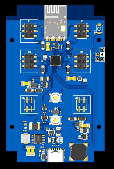
    But a few weeks ago, I started designing the latest iteration. Instead the ATTiny (which I now consider very expensive) it uses the Puya I am simultaneously trying to bring to life. I also took the BOM optimization ideas that I learned recently to my heart and I have redesigned the controller brick entirely to keep the costs really down. Here is what it is supposed to do, as well as a picture of the designed board:

    • runs off 18650 li-ion cell, or 2 in parallel. This means a *lot* simpler charging
    • I am using IP5306, which is a Chinese chip designed for power banks. It integrates charger (2A max) and a boost converter to 5V capable of 2.1A output into a single chip and single external coil. It has many drawbacks (can't power the device while charging, cannot be really controlled by the MCU, requires dedicated power button), but is super cheap
    • everything runs at 5V, including the motors
    • I have kept the 2 motors and 4 GPIO extenders and their reversible connectors made of cheap headers
    • onboard is single RGB light for signaling, buzzer for sounds, NRF24L01P+ Si clone for comms and a second button for the MCU for advanced functions
    • instead of INA219 and I2C I am using much cheaper INA180 and the ADC on the MCU to determine the battery level, total power envelope and left & right motor current to detect stalls. Motors and GPIO pins can be powered off by the MCU when needed

    I have an idea of a really simple and robust assembly of this (with the li-ion cells on the bottom part of the board). And overall, I think I have made the right calls in terms of usability vs price ratio. That said, at this point the board design is wishful thinking since I haven't yet brought the Puya chip - but it is also a lasting record of how well I read the datasheets, i.e. how much the design changes before the ordering. 

    If all goes well, I would like to have this ready for Xmas delivery:)

  • Puya has blinked!

    Zduka • 09/06/2026 at 21:09 • 0 comments

    Puya now blinks;-D All it took was downloading the CMSIS packs for Puya and core Cortex M0+, then creating the linker and startup scripts. This is because the CMSIS packs are for ARM Keil Toolchain, while I am using gcc `arm-eabi-none`. I did some guesswork and tweaking and the scripts now exists and blinky blinks;-D

    The simple cmake template with necessary files can be found here: zduka/puya-blinky: An attempt at a blinky for thePY32F030 chip I am considering for rckid. Might evolve into a template for puya projects in the future.

    And I am really excited that I will be able to debug the small chip too now - hopefully, compared to the serial printfs on the AtTiny,  this will speed up the development where I need to bring up the parts of the chip I need (I2C, RTC, PWM, Neopixel RGBs). So as always, to be continued:)

  • Puya Has Arrived!

    Zduka • 09/06/2026 at 11:21 • 0 comments

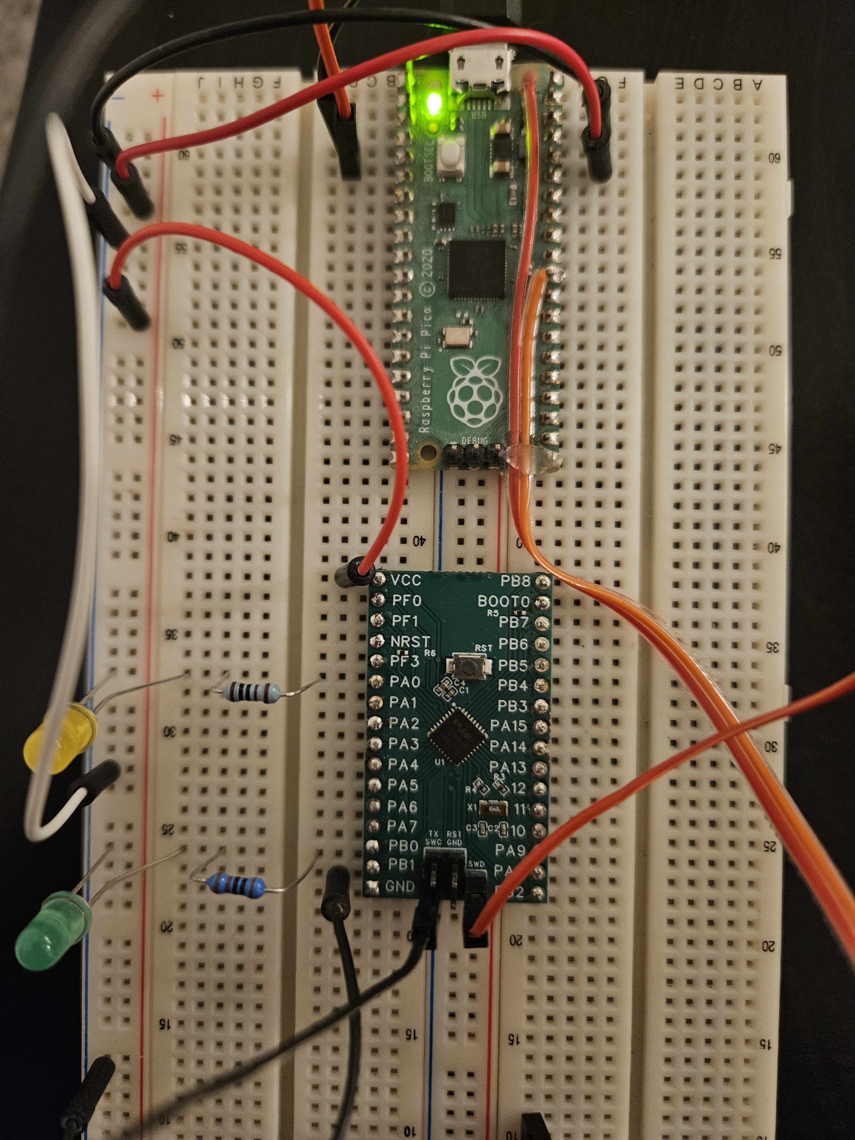
    The Puya breakout boards I have created have arrived. More specifically, the PY32F030: 

    I have been trying to bring it to life so far, and this is report about the work in progress,. because I am not at blinky yet:) But not all is lost:

    First I had to change my setup - for rckid's debugging I was using OpenOCD connected to raspberry pi GPIO, which worked nice so far, but required the actual Raspberry Pi. There is also the debug probe from RPi, which is essentially a RP2040 with the SWD and UART out and a few LEDs. I was always thinking that it would be really nice to have a cartridge for RCKid that does exactly this (and more - in the ATTiny3217 days I planned SWD, UART and UPDI interfaces). And because OpenOCD does not work trivially with Puya, this felt like a good option to try to switch. 

    But as I did not want to debug multiple things at the same time, I first just flashed the default debugprobe code to an old RPi Pico I had lying around unused (fun fact: This pico was used to prototype the rckid *before* the Rpi zero days (see the history log:). I also tried pyOCD, which looks a bit more modern and I was hoping I can run it from my laptop - which I can! 

    I then tried to list the targets and scope at the gpios to see if the SWD is working, and it seemed it was not/. But my mistake. The debugprobe will *not* detect a device is connected and connect to it automatically, you *must* tell it to. It took me some time to realize this when staring at flat scope lines at night:) But now I connect to the puya, I can flash, and I can inspect the chp state. So I know hardware-wise the puya is really simple to use, almost as much as the ATTiny was. 

    But this was the easy part - the hard part is figuring out the code to run. In the past I was shielded from all this by the RPi Pico SDK, but now I am digging through Chinese documents, ARM Keil CMSIS and friends. So I do not have a blinky yet. To be continued... 

  • BOM Optimization

    Zduka • 08/31/2026 at 20:09 • 0 comments

    Although the latest prototype (v3.2 Beaver King) has a few problems - most importantly the new headphone detection circuit is not working, I am now in a happy place as across all my prototypes, I have every hardware feature working at least once:) This is great, because technically I can just put together the working parts into a single prototype and call it a day. But at the Lancaster summer school I've been to, Paul Dietz was showing a super neat trick that makes a single LED both emit and sense light and I would really like to use it in my device, partly because the light detection sensor is a bit expensive and hard to get.

    But why stop at the light sensor you say:) So I decided that I should look at my entire bill of materials and see if I can improve things. And what I found shocked me!

    The numbers below are for my fictional order of 50 units, where the entire BOM of that would be roughly 1k EUR. Out of this, those are the biggest offenders:

    • 200 EUR for the accelerometer, which I use in the most primitive way, but I paid the premium because it also counts steps
    • 162 EUR (!!!) for 220uF capacitors for 3v3 buffer and headphones filter
    • 81 EUR (!!!) for the ATTiny3217 which is glorified IO controller. Note this is *more* expensive than the RP2350 which is the main brain.
    • 80 EUR for the light sensor, that is slow to measure, I use it in the most basic way, but I liked it because it also measures the UV light
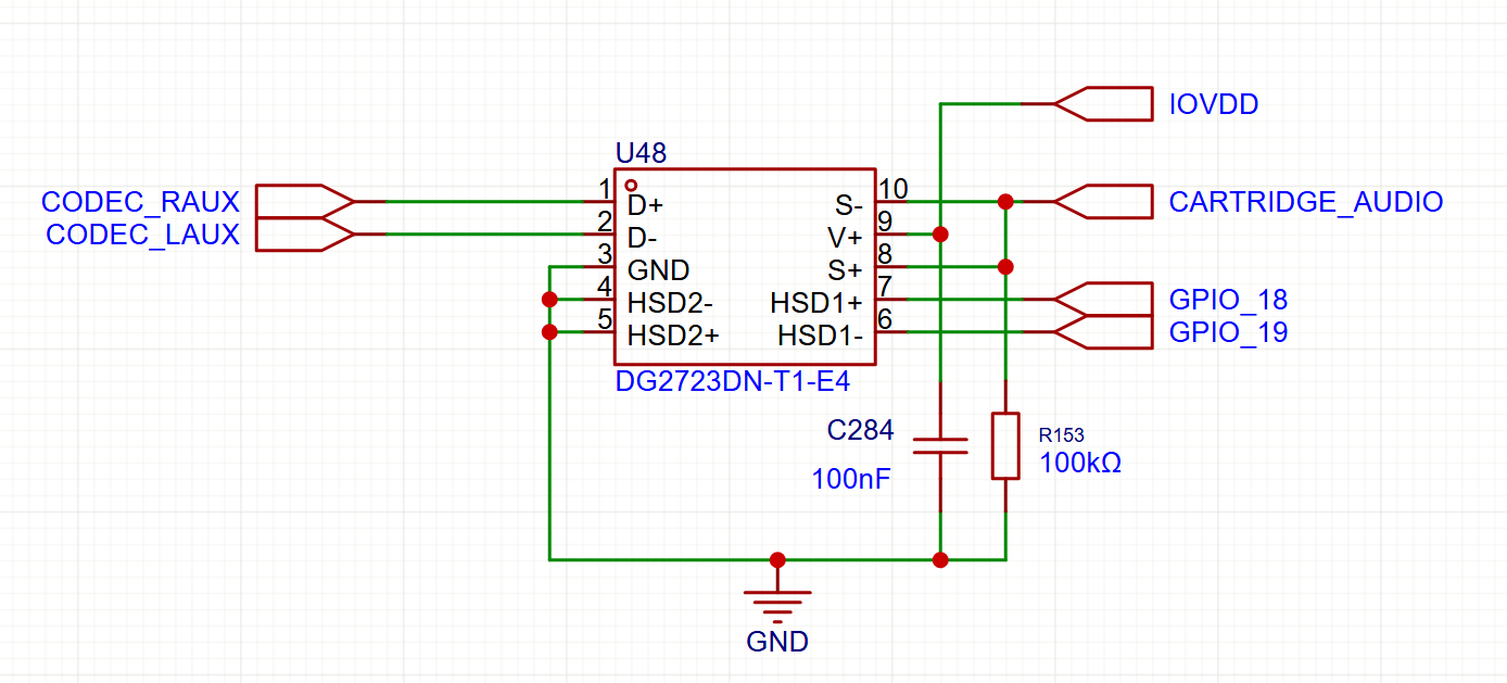
    • 55 EUR for the analog/digital cartridge mux which allows cartridge to output directly to the audio codec inputs (analog)

    Combined, this is roughly half of my BOM (the part of BOM that is assembled by JLCPCB anyways), which is crazy. So I started thinking on how to optimize it. As a programmer, I am probably the most upset (in the what is wrong with this world sense) with the fact that the tiny ATTiny (pun intended:) costs more than the powerful RP2350. I started researching at what are the cheaper options here and I was almost ready to defect to the PIC camp (funny enough atmels and pics are now both microchip so maybe not that bad for my karma), but the price difference will only be small.

    So I went radical - what are the *cheapest* MCUs available? I need them to work as RTC, have enough pins, have flash in them, and have enough power/peripherals to do what ATTiny did. I was really surprised when I found the Puya microchips line. They are super cheap, come in variety of packages (including my favourite QFN), have enough pins, are a lot more powerful than the ATTiny, and are based on ARM Cortex M0+ (similar architecture to the RP2350's M33). Crucially they can be programmed via ARM's SWD which I already use for the RP2350. And they are cheap - at "volume" pricing of 50 units, they'll cost only 14 EUR.

    The light sensor obviously goes and will be replaced by a cheap LED. But I have decided to also part ways with the accelerometer. Instead I'll get the cheapest accelerometer available, and I can always write the pedometer in software on the Puya chip, should I choose to (also, its power consumption is better that ATTiny's:). Cheap accelerometers will cost me 9 EUR for 50 units.

    As for the capacitors, I have two options. For some reason, I was using some really expensive ones - I can get 220uF caps for essentially half the price, or if I use 2x100uF instead, I can drop the price to 29 EUR only (if I find place on the board).

    Finally, the analog multiplexer for the cartridge is purely optional item and I do not have to have it assembled (I can revisit this in the future if I ever change my mind).

    Overall, my savings can be up to 10 EUR per device in BOM alone, which is HUGE:

    ComponentBeforeAfter
    Accelerometer200 (LSM6DSVETR)9 (MSA3S02)
    Capacitors162 (220uF)29 (2x 100uF)
    MCU82 (ATTiny3217)14 (PY32F030K28U6TR)
    Light Sensor80 (LTR-390UV)2 (cheap LED)
    Analog Mux56 (DG2723DN-T1-E4)0 (do not fit)
    TOTAL580 EUR54 EUR

    I was a bit worried though about the Puya MCU and I want to test it before redrawing my device and paying...

    Read more »

  • Jacdac!

    Zduka • 08/06/2026 at 20:17 • 0 comments

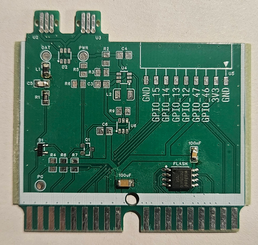
    I have been very busy with version 3.2 because I entered RCKid into the Device Prototyping summer school organized by the University of Lancaster (LINK). And while I have the feeling that I should have done this some 3 years ago, it was absolutely amazing and if you have a project you want to prototype, I highly recommend going in the coming years! The event is organized by https://prosquared.org/ where you should find more.

    First and foremost, you meet great people from all embedded walks of life, and they will have interesting comments about your device. For me this was the first time I talked about my device to others in person, and words cannot describe how cool it is:)

    The days are also filled with lectures and tutorials on various aspects of device creation and prototyping - technical, deeply technical, administrative, research-y. This year they covered things from how to solder (unsurprisingly I have failed that one:), SMT parts, creating devices simply and cheaply (two separate talks:), the evils and importance of certification (I still have nightmares about this), very cool tricks you can do with MCUs and LEDs (I will be using those in RCkid's next revision), and some cool HCI projects. It's pretty packed so I am sure I forgot some, but the point is that there is something for everyone, and even the talks where I thought I know stuff already are good to attend as the presenters are real professionals who often give things in context & perspective.

    The projects submitted range from ideas on paper to almost finished like rckid and the judges select a few good projects to give brief presentations and win some money (yay for rckid:), then all attendees vote for a project they like the most (yay for someone else:). (consolation price: quite a few people told me they really liked rckid and voted for it, if you are reading this and are one of those, thank you, it means a world to me!)

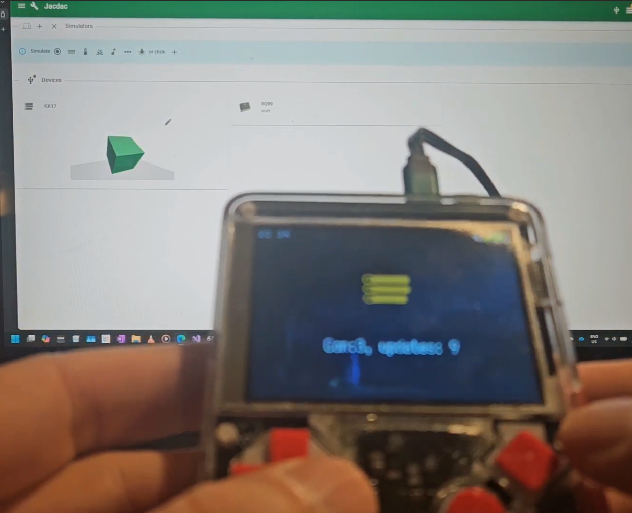
    The whole affair is organized by people deeply involved with the BBC:microbit and one of them, Steve Hodges, gave me a Jacdac starter kit under promise I will do something with it. And since for RCkid, everything is a cartridge away, I was pretty busy in the past few weeks with the Jacdac cartridge for RCKid, ta da:

    Its very cool how little is needed to make it work - the cartridge supports dual mode - RCkid can be either a service and provide peripherals it has such as accelerometer, buttons, rumblers, LEDs, etc., or it can be a brain (controller in Jacdac terms), in which case other devices are connected to it and the cartridge provides Jacdac bus with power as well (hence the extra circuitry).

    Software-wise Jacdac protocol is essentially an UART with extra tweaks over a single wire and this is rather easy and fun to program on RP2350 in PIO. So a few evenings after the board has arrived, I have RCKid expose its accelerometer as a Jacdac service.

    The Jacdac connector requires cartridge board thickness to be 1.6mm which in the long run is probably better for RCKid as well, as the standard width boards are ubiquitous and cheapest to manufacture, will likely work better with my plans for cartridge connector I will use if I ever create larger numbers of RCKid (simpler assembly, better electrical characteristics and tolerances, but requires custom stamped part), and overall the 0.4mm in extra space in the cartridge is probably not worth it anyways.

    But it means new version for the case & connector to accommodate the thicker pcb. I am also thinking how to actually make use of Jacdac in RCKid and I have a few ideas, so as always, stay tuned:)

  • Beaver King is here!

    Zduka • 07/12/2026 at 15:18 • 0 comments

    Past few weeks I have been busy with bringing the mk3.2 to life, and it has mostly been success:

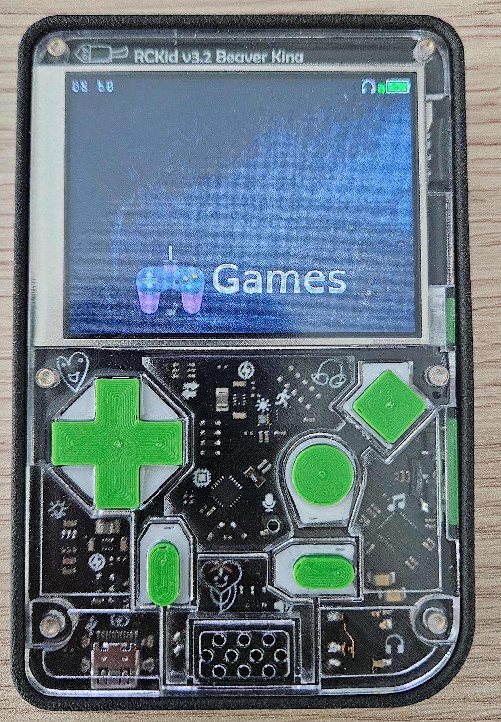
    - the enclosure (after some manual adjustments) looks great and fits nicely. The raised edges around the front cover work great too

    - battery connector works nicely - it is not perfect though, the clearance between it and the rumbler enclosure in the bottom case is a bit too tight and the battery wire is a bit longer than necessary

    - rumbler with sprint contacts works great! So much easier than clipping & soldering wires. The only thing that clouds my joy is the fact that LCSC discontinued (apparently, the page just says 404) the exact model I used. 

    - speaker with spring contacts works absolutely great too - even the enclosure made of the case works rather nice as it is already. I made some small mistakes so I had to print a frame ring for the speaker and I realized that I can actually turn this into feature as it makes the whole enclosure a bit easier to do & to glue the protective cloth. I might post details on this a bit later

    - new top buttons are great too! Their feel is so much better and the assembly is a lot simpler too. I also realized I can manually swap color mid-print, which means no more gluing of the two button parts together

    - and finally, the microphone seems to work rather well this time. I have only tested it with looking at the waveform, but I *can* produce a waveform this time;-D

    That said, there were some hiccups, two most important are:

    - the new headphone detection does not work at all. And I do not know why - the headphone detection line reads 0.3V whether headphones are connected, or not. I have verified the obvious (i.e. the headphone jack switch does indeed switch on/off)

    - the new side buttons do not feel better than the old ones - maybe even worse. Furthermore of the 3 devices I assembled already, 1 button was soldered wrongly (fixed that with a wire), and one was not properly working (part problem, not soldering, you need to really press hard on it in a special way to work)

    But overall, I am very excited as I can always go back to the old buttons & old headphone detection that worked. So finally, all hardware issues seem to be fixed now. Also, the new debug connector with the UART TX from both RP2350 and AVR are absolute godsend! 

  • v3.2 Beaver King (version 2)

    Zduka • 05/30/2026 at 17:58 • 0 comments

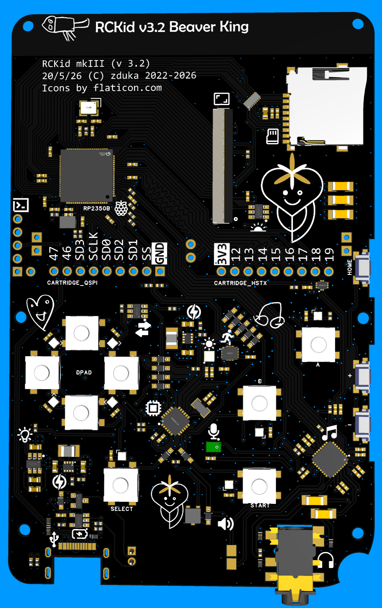
    I have decided to actually print even the prototypes in beautiful black & ENIG finish. How else can I judge if it really is as beautiful as I hope:) As part of that I have also decided to remove almost all of the visual clutter from the silkscreen. The outlines where top panel touches the PCB are not necessary to be visible. The text is not very useful for pre-literate children so I swapped it with pretty icons. The component markings are not necessary either, they mostly belong to assembly layer and will just make the board look uglier. 

    In EasyEDA this is super easy, I just right-clicked on the component, then Edit footprint -> for all and I moved all the silkscreen markings from silkscreen to assembly layer. The board preview looked super pretty, product like.

    BIG MISTAKE

    I placed the order and a few days later comes an email from JLCPCB to verify component placement. This has happened in the past a few times, but was always a formality - not once did I spot any error. But the boards were pretty expensive this time so I still do my due diligence and look carefully. I found 22 components to be badly oriented. 22!! Ranging from diodes all the way to big chips. 

    I verified all of them manually, indicated correct placement and sent the images back to JLCPCB. They were very nice and accommodating. I was very careful, tested everything twice, but I still have the nagging feeling in my head that I missed something and the boards will be broken. 

    I went to the editor and put all the orientation marks from assembly back to silkscreen. They will hopefully save me a lot of stress in the future, and they are barely noticeable. Clean silkscreen is great - empty silkscreen is not.

  • v3.2 Beaver King

    Zduka • 05/18/2026 at 20:56 • 0 comments

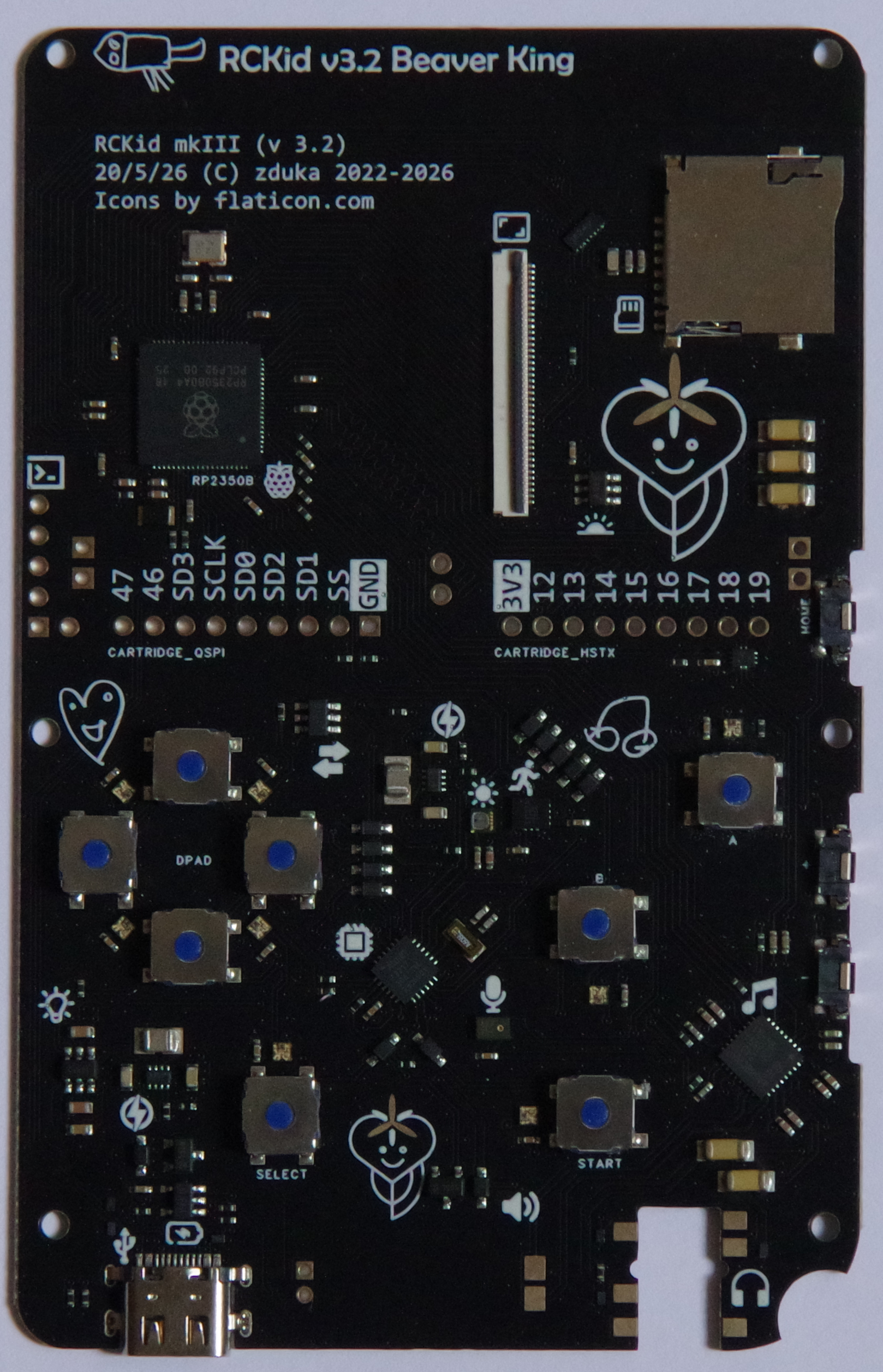
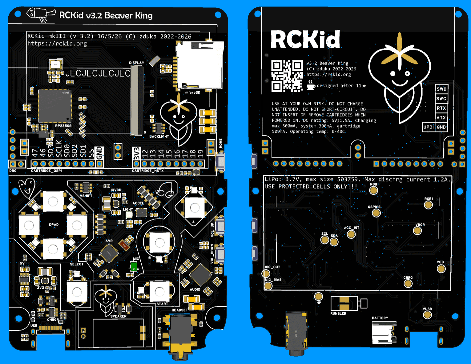
    Past few weeks I have been busy with yet another almost final revision of RCKid, 3.2, codename Beaver King (from now all versions will have names based on currently favourite animals of my kids as they get super excited when they see the names written on the boards). Below are shots of the final PCB - presented here in beautiful black & ENIG finish that I plan for the more bulkier orders later on. This one will be the boring green & HASL for cost savings though:)

    The version incorporates the lessons learned from building the SDK 1.0, some cost saving decisions and hopefully a lot of DFM improvements, namely:

    - the FM radio is gone. It can return in the cartridges, where fundamentally it belongs better. It simplifies the assembly process by not having to worry about the antenna placement, makes the BOM much easier (this was the only part that was not available directly from JLCPCB) and makes the audio design much cleaner because of the extra space I gain there. It clears one pin on the RP2350, which I put to use immediately in the analog/digital demux switch for cartridge pins (see below)
    - I am taking a bold step and making my own speaker enclosure. Previously I have used an already enclosed speaker from Samesky with wires that I had to solder manually. Now I am using non-enclosed speaker with spring contacts for much easier assembly, which is great. But I have to make the enclosure for it. The idea is that natural enclosure forms between the PCB and the top plate (you can see its outline in the image above on the PCB). I am not yet sure about the quality of the seal this will make, but I reckon its worth a try. The new speaker is cheaper, and louder, according to the datasheet.
    - I am changing buttons too: the side buttons which I had to solder manually to the bottom side are replaced with sinking ones that are larger, better centered (the actuators are actually close to the middle of the buttons) and will be soldered by JLCPCB. For the top buttons, I have used the super thin ones, without plungers, but making the plungers on the buttons themselves proved very difficult. Also I did not like the feeling. So now I switched to buttons with integrated silicone plungers, hoping that this would simplify the mechanical tolerances, and hence assembly complexity for the buttons
    - I have replaced rumbler motor with one that uses spring contacts as well and will sit under the PCB for yet simpler assembly
    - I have also changed the battery connector - I have found that I can buy the batteries I need with JST-PH connector as well, which is just large enough to fit under the PCB, and at the same time I am trying even different option where a special daughterboard with spring contacts will be soldered to the battery wires, making the assembly even simpler (I am scared that the battery wire will get squished when I close the PCB on the JST-PH connector and without transparent cases, there is no way to tell

    Five things were changed electrically:

    - LTR-390UV sensor for ambient light & sun detection. There was free room on the PCB, I already have the chips purchased back from mkII so no extra cost, and my hope is that the light detector will allow me to do very crude wireless transmission between two devices by blinking the display white opposite to the light sensor so that kids can exchange tiny pieces of information this way.
    - with the FM radio removes, I have added analog multiplexers & control line to two of the cartridge pins. These can now be used either as digital pins, or can be used as analog inputs to the audio codec (where the FM radio previously connected). This means cartridges can provide extra audio HW with ease (such as the FM radio:)

    - previously the board had electret microphone, but they did not work. I have tried everything to make them work, but to no avail. This time I am switching to MEMS microphone hoping this would solve the problems.

    - instead of double ground connection, the headphone detection circuit has...

    Read more »

  • Audio Woes

    Zduka • 04/12/2026 at 21:40 • 0 comments

    I am pure software engineer by trade, and while I can deal with digital circuits, analog circuits, of which audio is prime example as really hard for me, so the audio system of RCKid has been quite a journey so far...

    Bit of History

    Before working on RCKid, my MP3 Radio for kids used PT8211 and a class D opamp for a speaker. PT8211 is a really cheap easily solderable SOIC-8 I2S DAC. While I wanted to reuse my trusted setup, I ran into problems quickly as the SOIC chip + speaker amp + headphone amp were just way too big for RCkid. Also, the new batch of chips I ordered from China all came as duds. And finally, I did not have I2S pins available (this was the RPi zero time and the I2S pins were already used by the display SPI). 

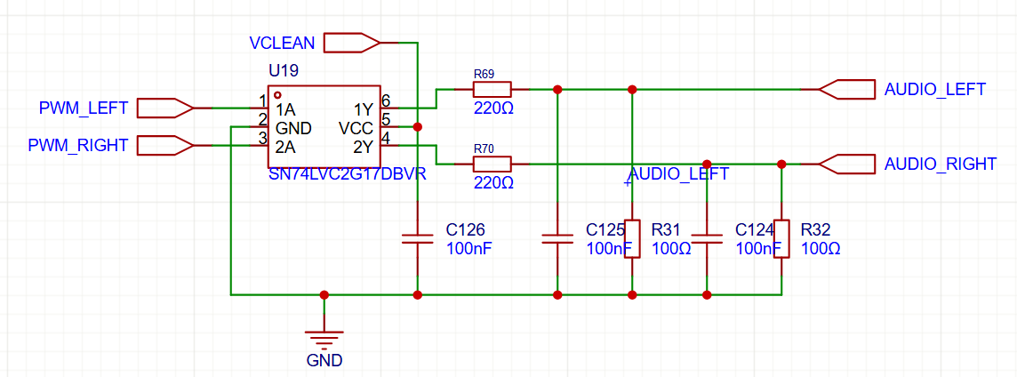
    So I started looking how the real Raspberry Pi was doing and I found the, in my opinion, ingenious way of using PWM via Schmitt Trigger (for voltage stability) and low pass filter for nice analog output, which is what the first RPis were doing:

    I have blatantly copied this design, the Schmitt triggers are actually capable of driving small headphones on their own, so I only needed a D-Class opamp for the speaker. I have used autogain microphone module from Adafruit and connected it to the ATTiny, which is just capable enough to record 9kHz 8bit mono audio and stream it to the RPi via I2C. 

    MkII

    When I switched to RP2040 and started the MkII, I have decided to reuse this new trusted circuit and attached it to RP2040 PWM pins as I have calculated that I can easily output 44kHz 8bit stereo audio this way. But when I listened to it, it sounded *awful*. I am no audiophile, but this was bad. Started hissing as soon as I enabled the playback and the quality of the output sound was terrible. With speaker, it was barely ok, but headphones were torture. 

    At first I brushed it off thinking this is probably just some noise from the breadboard (on which the device lived at that time), but when I got my first PCBs back, the same noise was there. This was the time when I added "audio woes" section in my TODO list as I tried almost everything. I double, and triple checked the schematics (there were some changes between Raspberry Pi versions, and I did not copy the schematics verbatim. No amount of component changes and value adjustments fixed the problems.

    Desperate, I turned to software. I fixed a few minor playback bugs, such as tiny hiccups during buffer switching. Those had no effect - as expected, but at this time I doubted everything. My lucky break came when one night I wanted to torture myself and listen to the exact same music on my laptop to rub salt into my wounds by hearing how it might have sounded. But it sounded awful too!

    Becoming Audiophile:)

    I quickly started researching and realized that with 8bit audio, the quantization noise (rounding to the 256 amplitude levels supported) creates the horrible sound. I could not do 16bit on RP2040 as the chip was not fast enough to give me all 65536 levels with decent sample rate, but luckily at 12bits the audio sounded already great. Nor did my kids complain about any sound issues:)

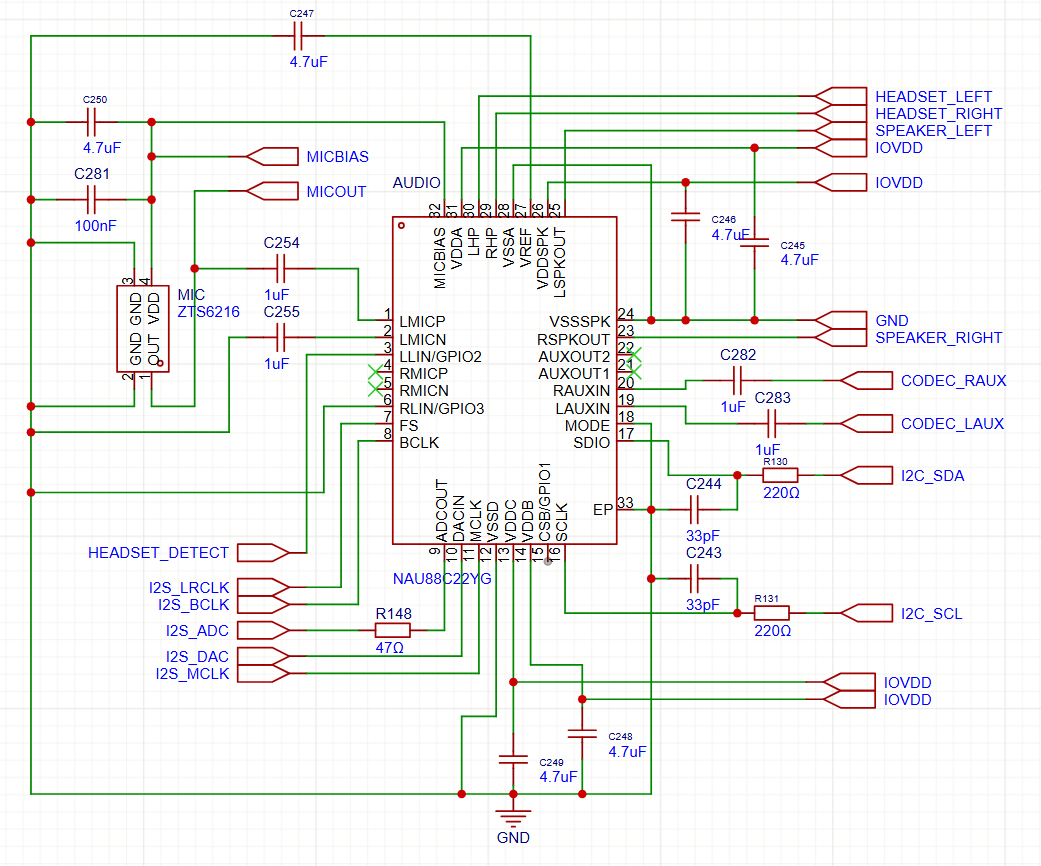
    But for MkIII I wanted something better. I realized audio codecs are not just compression programs, but also super useful chips that integrate DAC, ADC, amplifiers, equalizers and what not into a single, small package. I have chosen NAU88C22GY, which is really cheap and quite capable. Furthermore, it has allowed me to do proper microphone recording this time with the codec outputting in I2S, which RP2350 is really good at reading, thanks to the PIO.

    The noise came back! Though this time I blamed the data format first - the new chip was so good that the old MP3 files (I transcoded them many years back at 64kbps because the radio could not handle more back then) were pretty bad. So I retranscoded everything at decent bitrate and stereo and gave the devices to my kids.

    "Woooow, wooow! They are right here! I am at the concert!" my daughter started screaming...

    Read more »

  • RCKid Demo In The Browser

    Zduka • 04/01/2026 at 20:52 • 0 comments

    Allright, I promised audio, I know:) But:

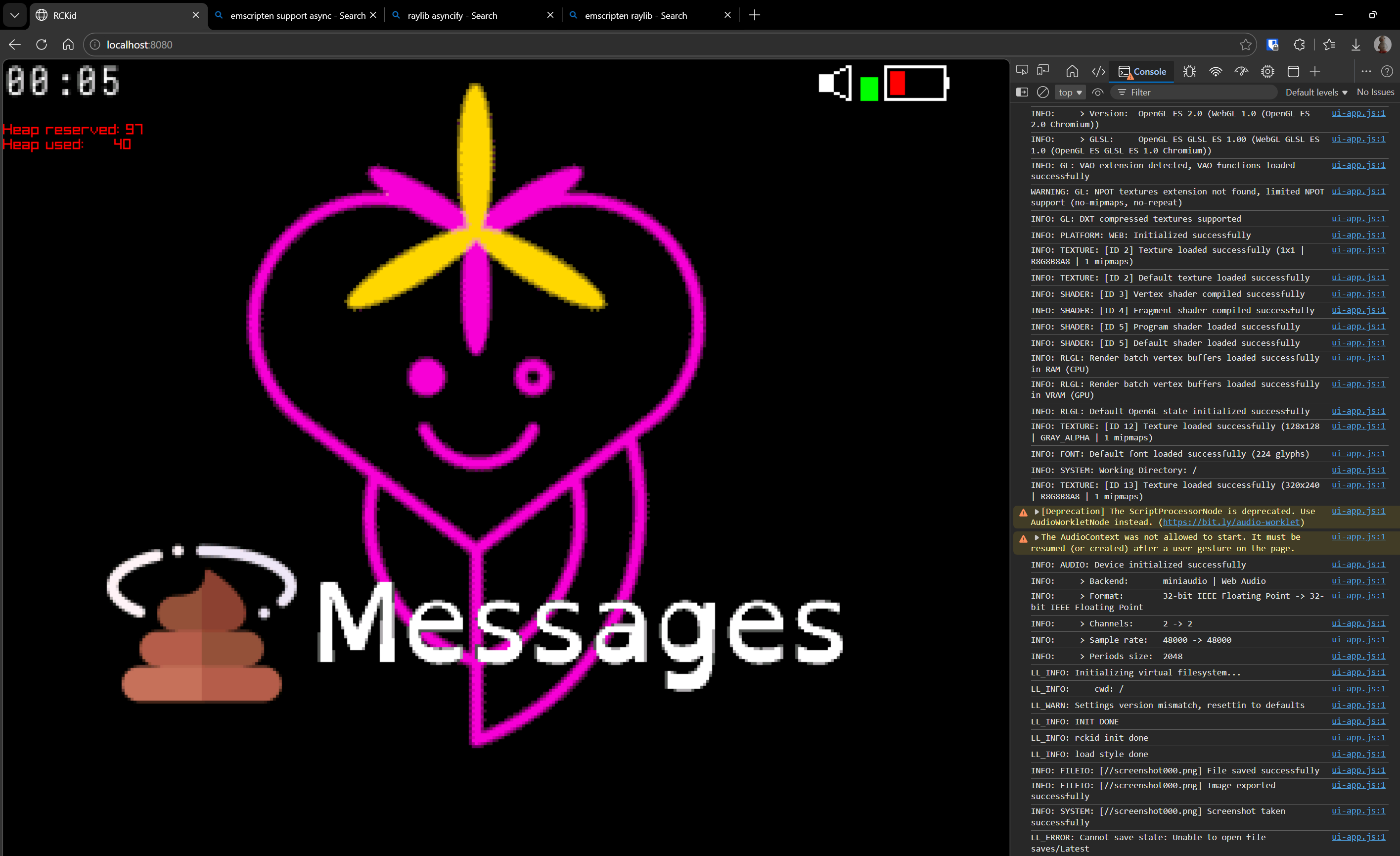
    This is RCKid, latest SDK revision that I am currently working on, running in browser (!) via Emscripten, thanks to Raylib. But what is the most impressive about it is that it only required about 90 minutes of work. Basically, I have done the following:

    1. installed the emscripten sdk (very easy)
    2. run emcmake with my cmakefiles. I got errors because libcurl not supported by emscripten and threads not supported by emscripten out of the box
    3. I only need pthreads for the libcurl, and I only need libcurl for the WiFi, which is optional capability so I just added code (long overdue) that allows turning that capability off, and then reran cmake
    4. now I got errors from my C++ code - particularly for the constexpr descriptors for the game engine objects (so that I can have kids program the device from the device itselfs, a feature I am currently building). The issue is I have lambda that calls method of an object inside the object before the type is finalized. gcc was ok with it, emscripten not. Cold sweat ran down my forehead because I was fighting those descriptors for the past 4 days and they are absolutely crucial. But then I realized there is a neat workaround. Those were non-capturing lambdas, so I can turn them to static functions. Emscripten was happy with those, and since the generators are already semi-heavy preprocessor affair, very little actually changed from user's perspective (you just don't specify the empty capture braces)
    5. fixed few other C++ irregularities between gcc/clang and emscripten and I got wasm and js files. 
    6. googled what to do with them, turns out you need to provide a html file that loads them. Internets were helpful and I quickly had a working prototype, by working I mean it now crashed in browser
    7. Added asyncify which raylib needs
    8. Realized that my html initialization runs the module in JS and also the module runs on its own, so it ran twice, not supported by emscripten & raylib. Fixed. 

    And I have RCkid fantasy console working in browser. I am really impressed how simple it was. What I could test works (graphics mostly), audio probably too, inputs, animations. SD card emulation (unsurprisingly) does not. And of course it needs a lot of polish, addition to CI, demo on the webpage, ...

    But yay:-) Well, I promise I will try to talk about the audio woes next time:)

View all 13 project logs

Enjoy this project?

Share

Discussions

Similar Projects

Does this project spark your interest?

Become a member to follow this project and never miss any updates