Zduka
Zduka-
v3.2 Beaver King
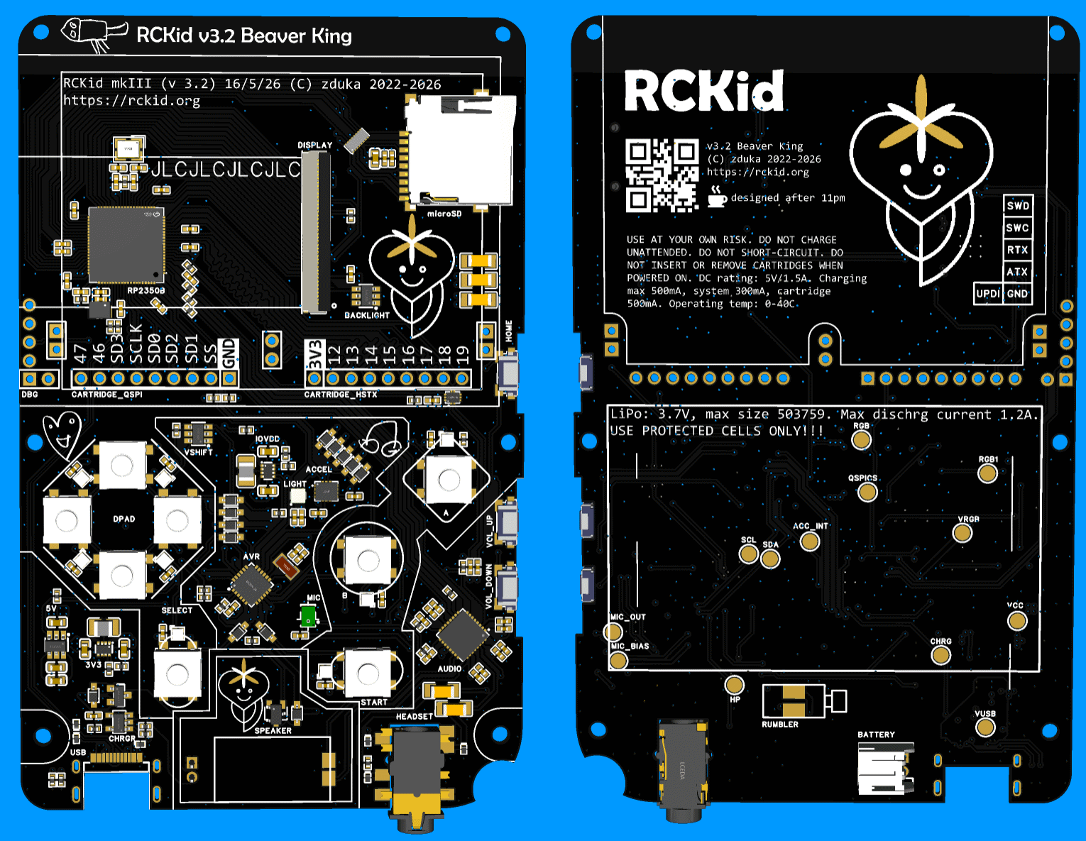
3 hours ago • 0 commentsPast few weeks I have been busy with yet another almost final revision of RCKid, 3.2, codename Beaver King (from now all versions will have names based on currently favourite animals of my kids as they get super excited when they see the names written on the boards). Below are shots of the final PCB - presented here in beautiful black & ENIG finish that I plan for the more bulkier orders later on. This one will be the boring green & HASL for cost savings though:)
![]()
The version incorporates the lessons learned from building the SDK 1.0, some cost saving decisions and hopefully a lot of DFM improvements, namely:
- the FM radio is gone. It can return in the cartridges, where fundamentally it belongs better. It simplifies the assembly process by not having to worry about the antenna placement, makes the BOM much easier (this was the only part that was not available directly from JLCPCB) and makes the audio design much cleaner because of the extra space I gain there. It clears one pin on the RP2350, which I put to use immediately in the analog/digital demux switch for cartridge pins (see below)
- I am taking a bold step and making my own speaker enclosure. Previously I have used an already enclosed speaker from Samesky with wires that I had to solder manually. Now I am using non-enclosed speaker with spring contacts for much easier assembly, which is great. But I have to make the enclosure for it. The idea is that natural enclosure forms between the PCB and the top plate (you can see its outline in the image above on the PCB). I am not yet sure about the quality of the seal this will make, but I reckon its worth a try. The new speaker is cheaper, and louder, according to the datasheet.
- I am changing buttons too: the side buttons which I had to solder manually to the bottom side are replaced with sinking ones that are larger, better centered (the actuators are actually close to the middle of the buttons) and will be soldered by JLCPCB. For the top buttons, I have used the super thin ones, without plungers, but making the plungers on the buttons themselves proved very difficult. Also I did not like the feeling. So now I switched to buttons with integrated silicone plungers, hoping that this would simplify the mechanical tolerances, and hence assembly complexity for the buttons
- I have replaced rumbler motor with one that uses spring contacts as well and will sit under the PCB for yet simpler assembly
- I have also changed the battery connector - I have found that I can buy the batteries I need with JST-PH connector as well, which is just large enough to fit under the PCB, and at the same time I am trying even different option where a special daughterboard with spring contacts will be soldered to the battery wires, making the assembly even simpler (I am scared that the battery wire will get squished when I close the PCB on the JST-PH connector and without transparent cases, there is no way to tellFive things were changed electrically:
- LTR-390UV sensor for ambient light & sun detection. There was free room on the PCB, I already have the chips purchased back from mkII so no extra cost, and my hope is that the light detector will allow me to do very crude wireless transmission between two devices by blinking the display white opposite to the light sensor so that kids can exchange tiny pieces of information this way.
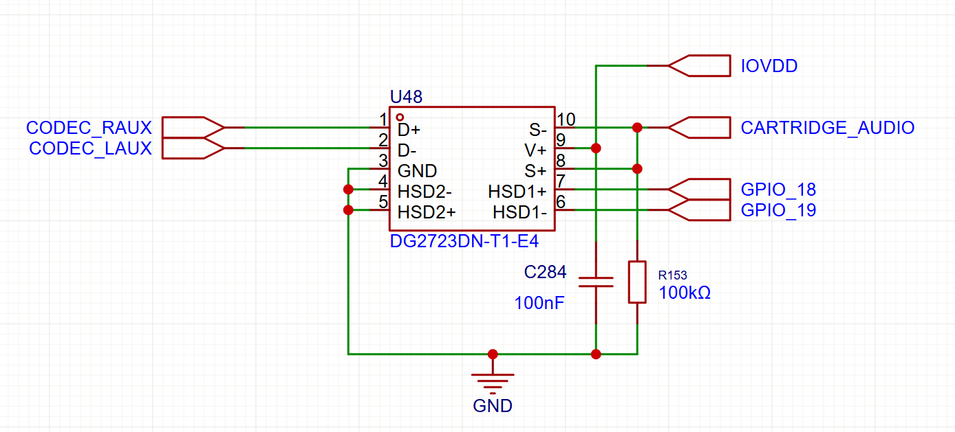
- with the FM radio removes, I have added analog multiplexers & control line to two of the cartridge pins. These can now be used either as digital pins, or can be used as analog inputs to the audio codec (where the FM radio previously connected). This means cartridges can provide extra audio HW with ease (such as the FM radio:)![]()
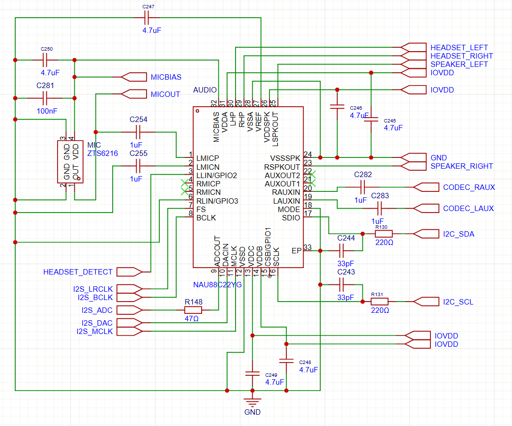
- previously the board had electret microphone, but they did not work. I have tried everything to make them work, but to no avail. This time I am switching to MEMS microphone hoping this would solve the problems.
![]()
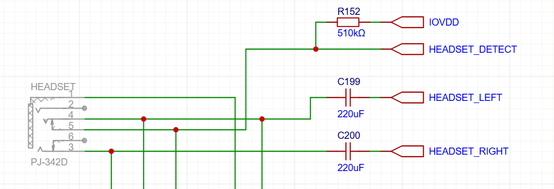
- instead of double ground connection, the headphone detection circuit has been reworked to use the integrated tip switch in the jack connector. This should allow me to detect even headsets with microphones reliably (previously this was flaky, I suspect because the microphone on the second ground ring changed the signal electrically to sometimes fall outside of the reliable high-low region)
![]()
- AVR and RP2350 are no longer connected with interrupt line (it was not used in the past). Instead those pins go to the now larger debug connector and are UART TX for both chips, which should ease debugging a lot
I have also reworked the case a bit - first room had to be made for the new components (speaker case, rumbler, battery connectors), but then I am also adding a slight curved rim to the top (see the incomplete picture below for the difference). The transparent SLA prints look very nice, but are very, very brittle, both of my kids managed to chip theirs already. So current plan is to print the back cover from nylon and the extra curved rim will protect the clear front case similarly to how phone protectors work.
That's it. I am running latest visual changes now and then letting the design sink a bit as usual in case I have forgotten something very important. Then in about a week, I am ordering the boards:) So wish me good luck, and if you happen to spot a mistake in the circuits above (especially the microphone which I am the least sure about), please, please, let me know:) Thanks!
-
Audio Woes
04/12/2026 at 21:40 • 0 commentsI am pure software engineer by trade, and while I can deal with digital circuits, analog circuits, of which audio is prime example as really hard for me, so the audio system of RCKid has been quite a journey so far...
Bit of History
Before working on RCKid, my MP3 Radio for kids used PT8211 and a class D opamp for a speaker. PT8211 is a really cheap easily solderable SOIC-8 I2S DAC. While I wanted to reuse my trusted setup, I ran into problems quickly as the SOIC chip + speaker amp + headphone amp were just way too big for RCkid. Also, the new batch of chips I ordered from China all came as duds. And finally, I did not have I2S pins available (this was the RPi zero time and the I2S pins were already used by the display SPI).
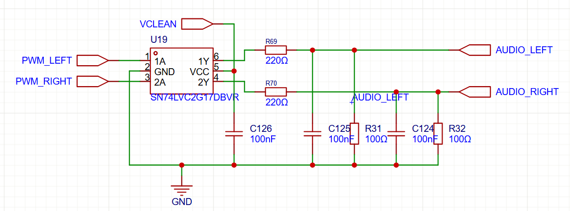
So I started looking how the real Raspberry Pi was doing and I found the, in my opinion, ingenious way of using PWM via Schmitt Trigger (for voltage stability) and low pass filter for nice analog output, which is what the first RPis were doing:
![]()
I have blatantly copied this design, the Schmitt triggers are actually capable of driving small headphones on their own, so I only needed a D-Class opamp for the speaker. I have used autogain microphone module from Adafruit and connected it to the ATTiny, which is just capable enough to record 9kHz 8bit mono audio and stream it to the RPi via I2C.
MkII
When I switched to RP2040 and started the MkII, I have decided to reuse this new trusted circuit and attached it to RP2040 PWM pins as I have calculated that I can easily output 44kHz 8bit stereo audio this way. But when I listened to it, it sounded *awful*. I am no audiophile, but this was bad. Started hissing as soon as I enabled the playback and the quality of the output sound was terrible. With speaker, it was barely ok, but headphones were torture.
At first I brushed it off thinking this is probably just some noise from the breadboard (on which the device lived at that time), but when I got my first PCBs back, the same noise was there. This was the time when I added "audio woes" section in my TODO list as I tried almost everything. I double, and triple checked the schematics (there were some changes between Raspberry Pi versions, and I did not copy the schematics verbatim. No amount of component changes and value adjustments fixed the problems.
Desperate, I turned to software. I fixed a few minor playback bugs, such as tiny hiccups during buffer switching. Those had no effect - as expected, but at this time I doubted everything. My lucky break came when one night I wanted to torture myself and listen to the exact same music on my laptop to rub salt into my wounds by hearing how it might have sounded. But it sounded awful too!
Becoming Audiophile:)
I quickly started researching and realized that with 8bit audio, the quantization noise (rounding to the 256 amplitude levels supported) creates the horrible sound. I could not do 16bit on RP2040 as the chip was not fast enough to give me all 65536 levels with decent sample rate, but luckily at 12bits the audio sounded already great. Nor did my kids complain about any sound issues:)
But for MkIII I wanted something better. I realized audio codecs are not just compression programs, but also super useful chips that integrate DAC, ADC, amplifiers, equalizers and what not into a single, small package. I have chosen NAU88C22GY, which is really cheap and quite capable. Furthermore, it has allowed me to do proper microphone recording this time with the codec outputting in I2S, which RP2350 is really good at reading, thanks to the PIO.
The noise came back! Though this time I blamed the data format first - the new chip was so good that the old MP3 files (I transcoded them many years back at 64kbps because the radio could not handle more back then) were pretty bad. So I retranscoded everything at decent bitrate and stereo and gave the devices to my kids.
"Woooow, wooow! They are right here! I am at the concert!" my daughter started screaming with headphones on as she was subjected to the power of 16bit 44.1kHz stereo audio for the first time:)
-
RCKid Demo In The Browser
04/01/2026 at 20:52 • 0 commentsAllright, I promised audio, I know:) But:
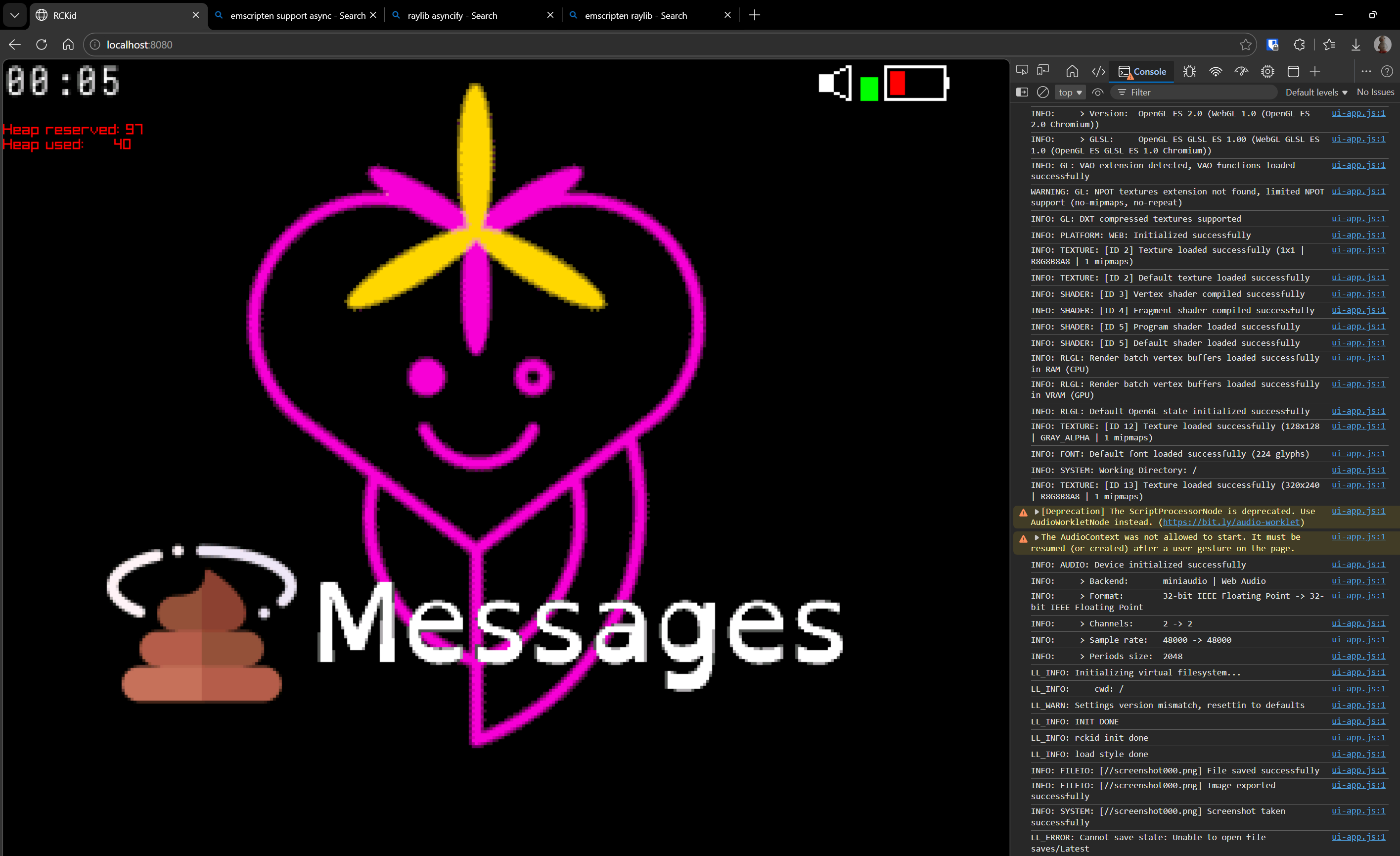
![]()
This is RCKid, latest SDK revision that I am currently working on, running in browser (!) via Emscripten, thanks to Raylib. But what is the most impressive about it is that it only required about 90 minutes of work. Basically, I have done the following:
- installed the emscripten sdk (very easy)
- run emcmake with my cmakefiles. I got errors because libcurl not supported by emscripten and threads not supported by emscripten out of the box
- I only need pthreads for the libcurl, and I only need libcurl for the WiFi, which is optional capability so I just added code (long overdue) that allows turning that capability off, and then reran cmake
- now I got errors from my C++ code - particularly for the constexpr descriptors for the game engine objects (so that I can have kids program the device from the device itselfs, a feature I am currently building). The issue is I have lambda that calls method of an object inside the object before the type is finalized. gcc was ok with it, emscripten not. Cold sweat ran down my forehead because I was fighting those descriptors for the past 4 days and they are absolutely crucial. But then I realized there is a neat workaround. Those were non-capturing lambdas, so I can turn them to static functions. Emscripten was happy with those, and since the generators are already semi-heavy preprocessor affair, very little actually changed from user's perspective (you just don't specify the empty capture braces)
- fixed few other C++ irregularities between gcc/clang and emscripten and I got wasm and js files.
- googled what to do with them, turns out you need to provide a html file that loads them. Internets were helpful and I quickly had a working prototype, by working I mean it now crashed in browser
- Added asyncify which raylib needs
- Realized that my html initialization runs the module in JS and also the module runs on its own, so it ran twice, not supported by emscripten & raylib. Fixed.
And I have RCkid fantasy console working in browser. I am really impressed how simple it was. What I could test works (graphics mostly), audio probably too, inputs, animations. SD card emulation (unsurprisingly) does not. And of course it needs a lot of polish, addition to CI, demo on the webpage, ...
But yay:-) Well, I promise I will try to talk about the audio woes next time:)
-
Mark III (aka last year)
03/24/2026 at 22:20 • 0 commentsAfter xmas 2025 I was in a good shape. I have delivered two working RCKids to my betatesters and they were inseparable from the device. I have also experienced my personal variant of the Tetris effect - once I made the tetris game for the device, development grinded to a halt since I spent most of my free time "betatesting" myself. And a few more clouds popped on the sky relatively soon:
My kid's devices actually did not have the cartridges. I should really say did not have *removable* cartridges, as the cartridge was still inside the device, just the 3d printed cover did not have the hole necessary for its removal. I have realized that the precision machined pins were all too easy to be destroyed (bent) by normal use. 4y old would destroy that in a matter of minutes.
When you started charging the device via USB, it became unusable as the buttons went all crazy with phantom presses. It took me a while to figure out what went wrong, but here it is: Through most of the revisions, I kept basic structure that I used already in my previous mp3 player project - the big chip (RP2340, RPi Zero, etc.) does almost all the hard stuff, but there is always ATTiny on the side, which is always powered on, manages the power, buttons and other important (or simple tasks). The ATTiny communicates with the big chip via I2C. And one of its jobs is to measure the voltage for a poor man's battery gauge. Normally you would need a pin an ADC for this. But all my pins were used. Luckily there is a really neat way to measure VCC with ATTiny without wasting a pin - you tell the ADC to measure internal reference instead. The ADC runs off the VCC, how much it measures can be converted to the VCC value. This seemed perfect - I do not need a DC-DC converter or LDO for the always on ATTiny, I do not waste a pin, and I do not have to turn it on or off. I2C is also fine, as it will be pulled-up externally to 3V3 and the AVR only even pulls low. Since I did not support going VCC below 3.3V at the time anyways, this seemed perfect. Unfortunately, when AVR is powered from 5V, the 3v3 is just at the edge of low to high input transition, and more often than not, the I2C IO was misbehaving because of that.
I did not have any more displays and had to order more. As I had big plans, I just repeated my previous order from AliExpress, just this time with 20 units and waited. Also, Raspberry Pi has created the RP2350 - much better chip (M33 vs M0, 2x memory for 512KB, more pio, more DMA, etc. And crucially ability to have external RAM - imagine if my cartridges could support external RAM next to the flash as well. But I knew from my past that feature creep is real danger, and so I resisted, almost tearfully. Then the new displays arrived.
Same display, same hand solderable connector, same everything, including the URL from which I ordered. But none of the displays worked. But none of them worked. Frustrated, I tried everything, and then I realized that on the display back, literally in a smallprint, there was a teeny tiny difference, my old 2 displays ended with 8, this one ended with 16. You probably guessed it, they were hardwired to 16 parallel 8080 MCU interface. The display I have been using so far was no longer produced.
A sane person would be depressed at this point. I was ecstatic - this was my justification for going with RP2350 without giving in to the peer pressure. See RP2350 had one more huge advantage - the B variant with a few more GPIOs. Now if I get this chip, I will have enough pins to drive the 16bit display:) No other way. Except of course, I also started learning about DFM and figured out that if I have QFN chips assembled already, I can also throw in a nice display FPC connector for almost no extra cost. And I could get FPC connector 8bit display, but pssst:) RP2350 is the future!
And indeed it was! I redesigned everything - but most importantly I have added 1.5mm of thickness to the device which is barely visible, but allowed me to put components *under* the display too (the RP2350 is *bigger*) and with this extra room for placement & layout and extra pins to use, I decided to go with proper sound via I2S audio codec. Feature creep came back with vengeance though - audio codecs are amazing! So the microphone switched from PDM to electret and I used the audio codec. And since I had some free audio inputs, I decided to also throw in an FM radio. I have of course fixed the power problem with a fancy new PMIC chip that I read in one of its datasheets (it came with 5) always regulates the system voltage above a certain threshold via integrated boost controller. I also changed the cartridge connector - it now uses daughterboard and antenna springs for connection with the cartridge being just a PCB with gold fingers (they are actually HASL lead free fingers to be precise, but they work).
Measure twice, cut once
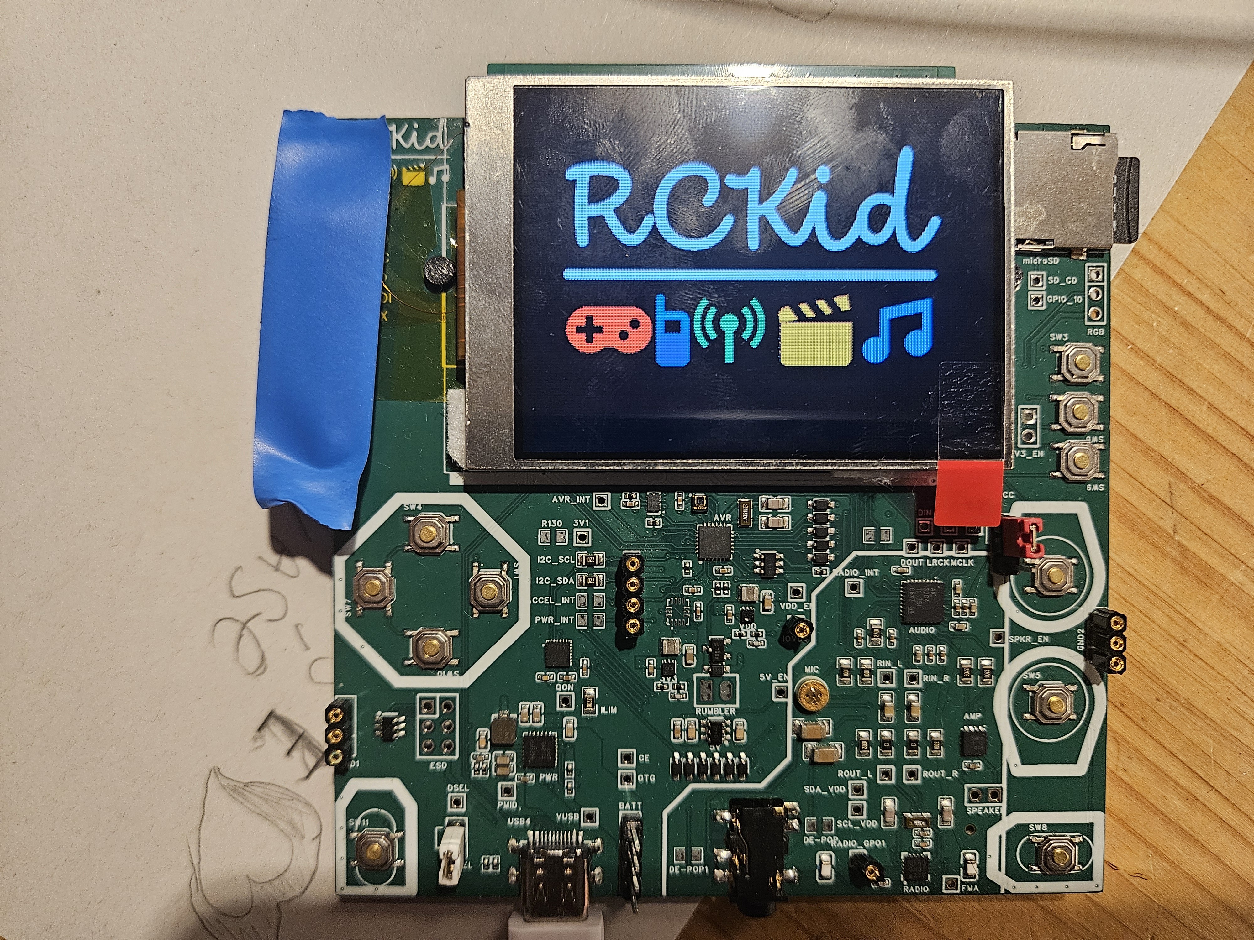
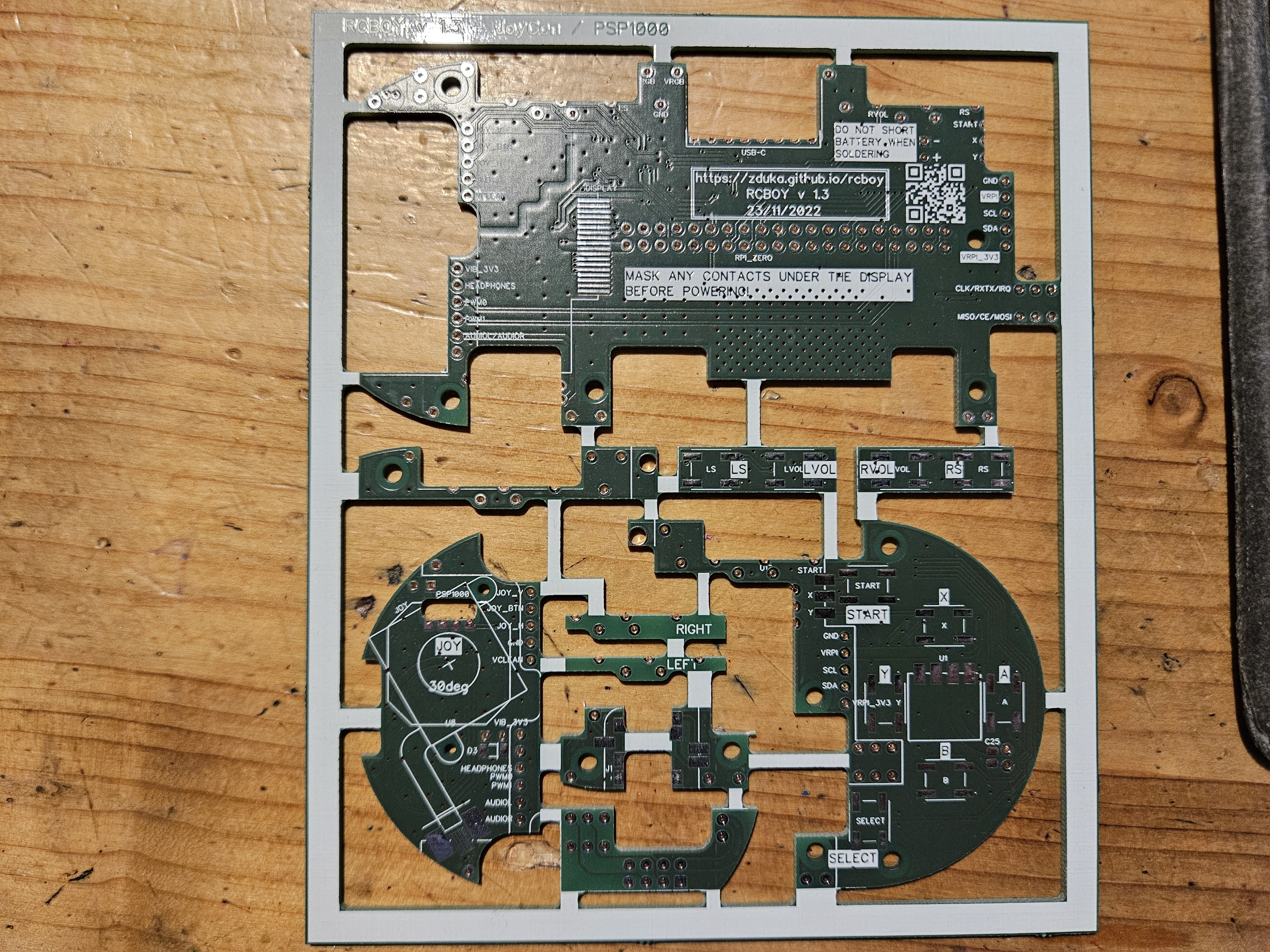
Or really verify semantics & PCB 5 times, do automated assembly once. I have also realized that the three revisions I did in with the mkII version were completely unnecessary if only I had a board that I can solder and desolder things myself with enough test points. I could not do this - the device is small, and all the passives were 0402, way too small for me to handle. So this time, instead of going to the desired form factor first, I have created a 10x10cm development board that had everything I wanted to have in mkIII surrounded by redundant traces, test points and large 0805 components that I knew from mark I with RPi Zero are at the edge of my skill.
Except of *all* the connections, I completely forgot to use RUN pin of the RP2350 in the schematics, hence DRC did not pick it up, and this enormously vital pin (if left unconnected, RP2350 will not boot basically) was left without even a testpoint. Luckily I know a guy who is next level in soldering and he attached a teeny tiny wire to the barely visible QFN pad on the side without bridging the rest. I had my dev board!
![]()
Don't trust components with multiple datasheets
At least if you are amateur like me. Turned out that the PMIC chip did not do what I wanted from it (won't regulate VSYS when powered from batt), and the audio codec did not work with the microphone - I went again into overdrive and added not just one microphone, but a second one via the headphone jack as well because why not. 2 microphones sharing same micbias driver, bad idea. Both components came with multiple hudndred+ page datasheets, which I did read, but missed this vital information.
But now the devboard with its many testpoints paid off. I have ordered simple breadboard converters populated with NAU88C22 audio coded that I found, which looked much better - worse audio, but integrated speaker driver as well. Most importantly the datasheet looked simple.
So I ended up with the following architecture (in beautiful handcrafted ASCII art form):
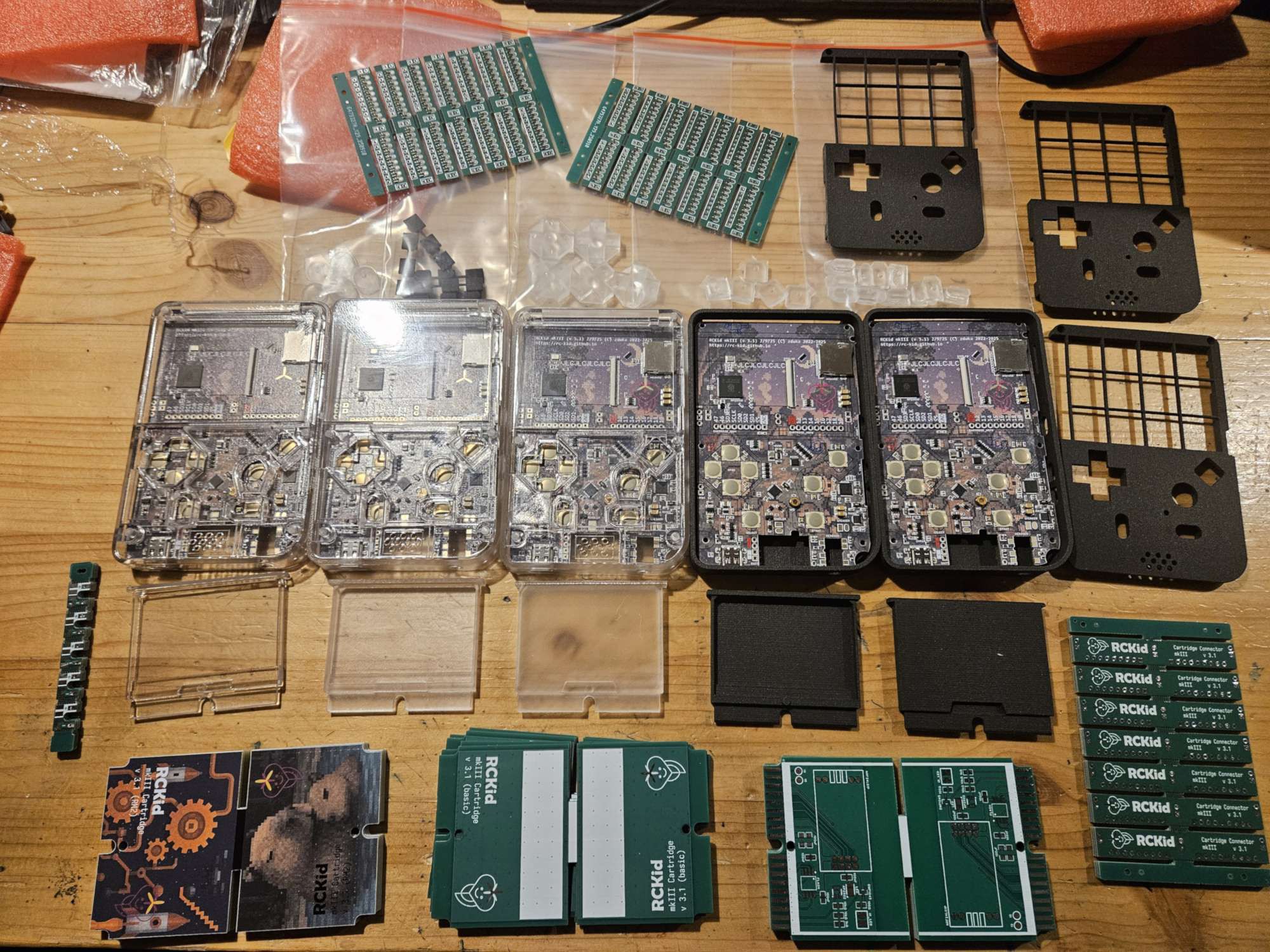
And it worked! This time I had 4 devices for xmas:-) I have also tried 3d printing services, mainly because the Internet said that transparent cases can be made this way and I saw my son being so very excited about a see-through xbox controller he saw in a shop. I have also experimented with full color silkscreens. For normal use they are rather expensive by my standards, but I got some for free, thanks to JLCPCB. I must admit the cases turned out amazingly well:
![]()
In the end, I do not think I will keep them for the main case - it is mostly obscured by the components, battery and display and I do not need the ENIG surface they require. On the other hand, the cartridges with full color silk-screen look absolutely amazing - and they can use the ENIG finish for the cartridge connector.
My parting comment for today: SLA resin prints are *not* thermoplastics, so using your soldering iron to melt in it threaded inserts for assembly will break them. I learned it the hard way.
Up next: Audio system (because analog circuits scare me:)
-
Meet the family
03/19/2026 at 14:14 • 0 commentsBe warned, this will likely be a bit longer post where I want to talk briefly about all the shapes and forms that RCkid had over its history. It all started as a humble Remote Controller for kids that would just put together some spare MCU[1], thumbstick and some radio to control plethora of pretty ancient LEGO technic motors I had lying around. Spoiler alert: they are still lying around, but their time will come!
Feature Creep...
...is a real thing. I quickly realized that with an MCU, I can do a lot more and the device grew to also support walkie talkie, simple Nokia screen, simple games, multiplayer games (I have walkie talkie, repurpose for multiplayer), but this required beefier MCU, which enabled better display, and so on. Long story short, all of the spare parts I wanted to put into the project at the beginning are still lying in my drawers somewhere. In fact, I have a lot more spare parts for future projects now:)
One important design step was when I updated the MCU from ATTiny3217 to RP2040. At the time this was the new MCU from Raspberry Pi shrouded in mystery. I have got my hands on RPi Pico board and poked around the datasheet and tried the basics such as talking to an ILI9341 screen. I really liked programming for the chip, and I started thinking about RCKid more seriously at the time, profiling it as a STEM education toolkit where kids would be able to create their own simple games. I did some PCB routing on my chosen formfactor (horizontal, pill shaped, very round & toy like), work progressed and I was a happy man.
But I was mortified of the chip's QFN package (words cannot describe how bad I am at soldering, but some of the prototype pictures later in this post might). In the end I gave in and I upgraded to RPi Zero.
Yet Another Retro Gaming Handheld
With RPi Zero I had all the power of Linux available and I used it "well", The first prototype & firmware was essentially heavily stripped down Raspbian with retroarch, vlc and my own GUI created in Raylib. It was full linux, so adding things was easy and it would be an insult to leave the abundant power of the RPi chip at idle. So after a few months, it did oh so many things - played games (up to N64), played video, played audio, had WiFi and you could SSH to it, it could send messages through NRF24L01P radio, and at this point being true to its name, had next to it a breadboard a ball of wires that was lego remote controller (more on it sometime later:)
But feature creep was still a thing - I have discovered LoRa and realized that I can increase my range by a lot with it. But its expensive, so I naturally wanted to have both LoRa and NRF. And the device was starting to be really, really crowded.
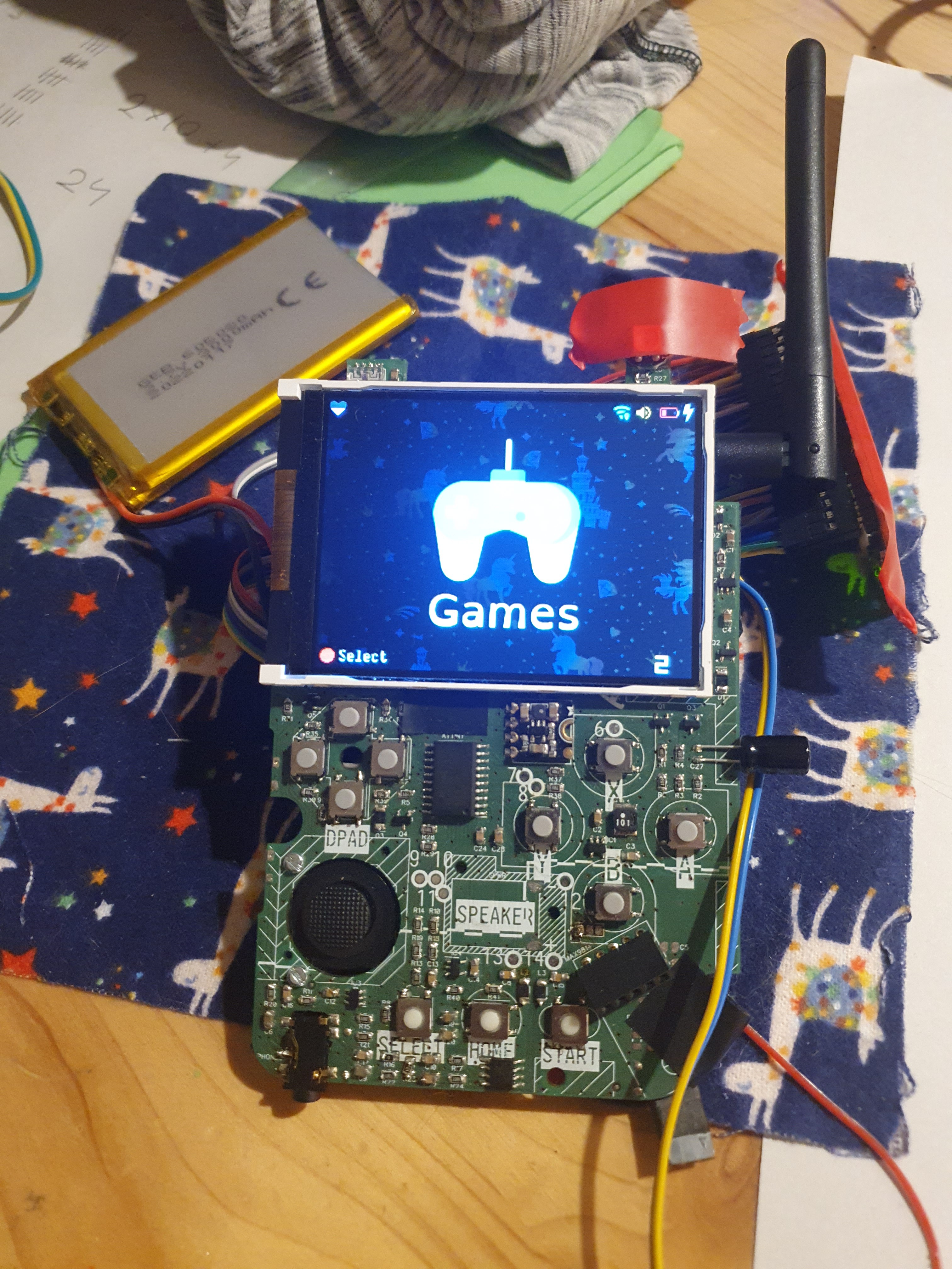
![]()
The image does not do it justice, but it consisted of a really intricate layers of PCBs in strange shapes that were soldered together, sometimes in right angles to give the device its shape. It is fair to say at that point DFM held no meaning for me.
![]()
Going Vertical
But then I had a revelation - the pill form factor was dead end:-) I have switched to vertical layout, like the original GameBoy had. By doing so, I got about 50% more volume, room for thumbstick and dpad, drastically simpler PCB stackup, much better thermals and far easier routing and assembly (yet I still managed to shoot myself in the foot by some clever use of right angle PCB soldering:). All this for a device that looked a lot more modern and slimmer.
![]()
The bigger problem was that I really did not enjoy programming the device (and I am software engineer by trade). Fair warning - my opinions below are just mine: I liked Raylib for its simplicity (and it is the only part that survived till now), but I am C++, not C person, and some of the architectural choices were perplexing. Performance was not stellar either, I could hardly squeeze out 30fps (interestingly though screen tear, which I feared because it used SPI with no tear mark info to update parts of the display at a time to save bandwidth (courtesy of juj/fbcp-ili9341: A blazing fast display driver for SPI-based LCD displays for Raspberry Pi A, B, 2, 3, 4 and Zero), did not visibly happen). The rest of the software stack was far worse though - I learned to appreciate the GPU drivers a RPi and realized that their design was really clever - a lot of the things I feared (such as showing overlays of my gui over other apps that will be running) were extremely simple. Documentation was not though. I spent most of my time sifting through internet finding bits and pieces.
The biggest problem was that I could not convince myself that giving this to my kids, is a good idea as it would be yet another screen to consume stuff on (and one that I would have to maintain for them:).
Crosssing the Rubicon
So I realized I wasted a year of my life. Back when I had the RP2040 prototype, I was happy - the chip was super fun to program, just enough power to do what I wanted, no retroarch, no linux stack. It was perfect. Except for the QFN package. But we do live in amazing times, and automated assembly, while still pretty expensive, cost around same amount that people spend in pubs or so. I crossed the rubicon, went back, resurrected the old RP2040 project, converted it to the amazing vertical layout and realized that I can make it *much* smaller - yet have enough room for all the peripherals I envisioned (I was stuck in the LoRa + NRF world still).
At this point another revelation came to me: RP2040 was really amazing chip, but unlike any other MCUs I worked before, the flash was not integrated. At first, I viewed it as a minor annoyance as I had to place & route another component, but then I remembered the old days and gameboys and segas and how they all had cartridges. You swapped cartridge and you had completely different game. O... K..., but digital content download is oh so much better, right? Well, not when you are a kid (more on that later), and digital content download will never add an accelerometer to your cartridges, or camera, or, wait... LoRa, or NRF, or WiFi (which is the one good thing I lost when I switched from RPi Zero to RP2040).
The Humble Cartridge
And so cartridges become part of RCKid's identity: the base hardware is simple, the flash for RP2040 and whatever else you might want to have sits in the cartridge and can be swapped in & out. At this time I used the precision machined pins for a really reliable contact and the mkII was born (pictured here with the backside showing the cartridge connector, unpopulated NRF and working display from front):
![]()
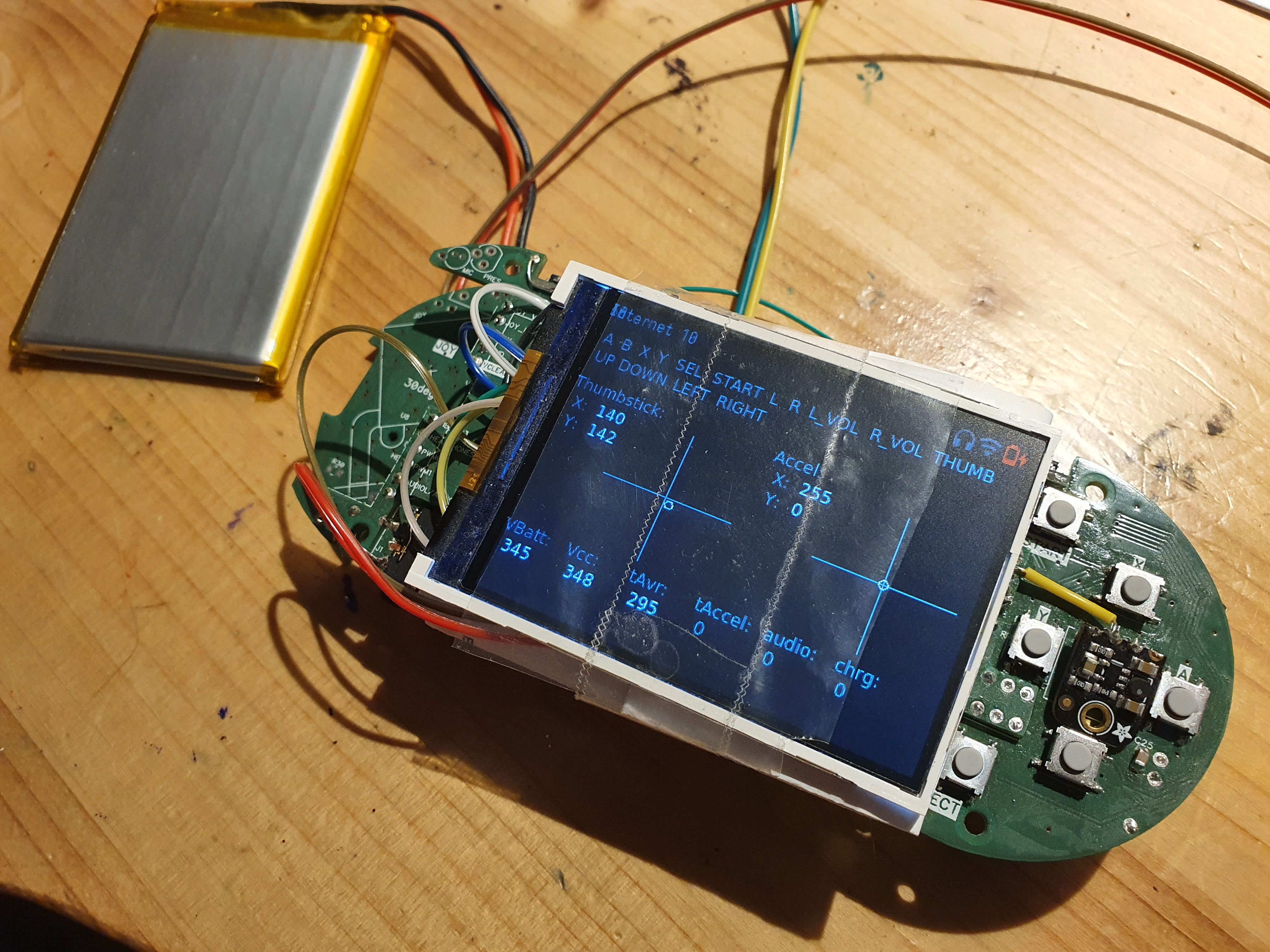
This is, sadly, still heavily abridged. The mkII went through great many PCB iterations. Mostly to deal with coil whine (unsuccessfully), added RGB lights everywhere, and power management - after watching some youtube videos, I am really scared of LiIon batteries:) Then xmas 2024 came and I had 2 devices ready for my betatesters. This is important, I had exactly two working devices ready. At this point the device did the following:
- 320x240 IPS display connected via 8bit 8080 interface and controlled by PIO on RP2040 (oh-so-satisfying:)
- PWM sound - I essentially copied the sound output of early raspberries with a Schmitt trigger and a filter. I then spent months poking around it with oscilloscope and multimeter trying to figure out why my sound sounds so horribly bad, only to realize that the circuit was right and this is just the nature of 8bit audio. Updated my PWN to 12bit and was happy.
- accelerometer, light sensor, PDM microphone, the cartridge of course:)
- C++ SDK where I implemented a few games (tetris, space invaders, sokoban, pong, 15 puzzle), mp3 player and a few utilities (clock, data sync).
- SD card inside for data storage
One thing that deserves special mention is the absolute ease of use with which the RP2040 can be reflashed from any computer via the UF2 bootloader - absolutely amazing!
At this point RP2350 was hot & new and I was debating with myself whether to give in to feature creep again, but I knew better. I felt like physics at the end of 19th century - everything was beautiful, and I only had a few tiny problems to fix. Boy was I wrong...
TO BE CONTINUED...
[1] ATTiny3217 - historically I have been using AVRs ever since university, barebones, not Arduino. My beef with the older versions was the 6pin ISP programmer, but the new ATTiny series programmable via the UPDI (1 pin and serial-to-usb programmer simple hacking is a bliss. The chip is pretty powerful too with really decent ADC, RTC support, good sleep modes and relatively large number of pins, all of which I put to good use in this project.
-
Hello World!
03/17/2026 at 22:35 • 0 commentsI have been working on this "quietly" for the past 3+ years with various iterations, so I have a huge backlog of technical details and opinions that I would like to eventually share here, piece by piece as I will find some time to choose what its interesting and write it down, so stay tuned:)
Let me start with technical details:
- RP2350 MCU from RaspberryPi that mixes raw power (520KB RAM, 2x Cortex M33 cores at 150MHz with overclocking possibility) and ease of use (C++ SDK). Further supported by great community and skillfully designed so that programming it is *fun* even for experienced developers (PIO)
- unique cartridge system: the firmware is not stored on the device, but in every cartridge. Cartridges can be swapped, shared, or reprogrammed with any computer easily. On top of the mandatory FLASH for the firmware, cartridges contain 8 high speed digital pins (HSTX, SPI, I2C, UART, PWM) and 2 analog pins to enable hardware tinkering
- 2.8" 320x240 IPS display with 65536 colors. Perfect for retro gaming and pixel art with enough catchy detail, but not too many pixels to design. 60 FPS refresh rate.
- 16bit stereo sound (headphones & mono speaker) with up to 48kHz playback. Powerful enough for MP3 playback
- SD card for media & settings, up to 64GB supported. FAT32 and exFAT filesystem - DPAD, A, B, Select and Start buttons with customizable RGB backlight
- 3 axis accelerometer with integrated pedometer
- rumbler for haptic feedback (simple motor)
- 1300mAh LiIon rechargeable battery with USB-C charging, or 3x AAA batteries, both options should give around 10 hours of active time.
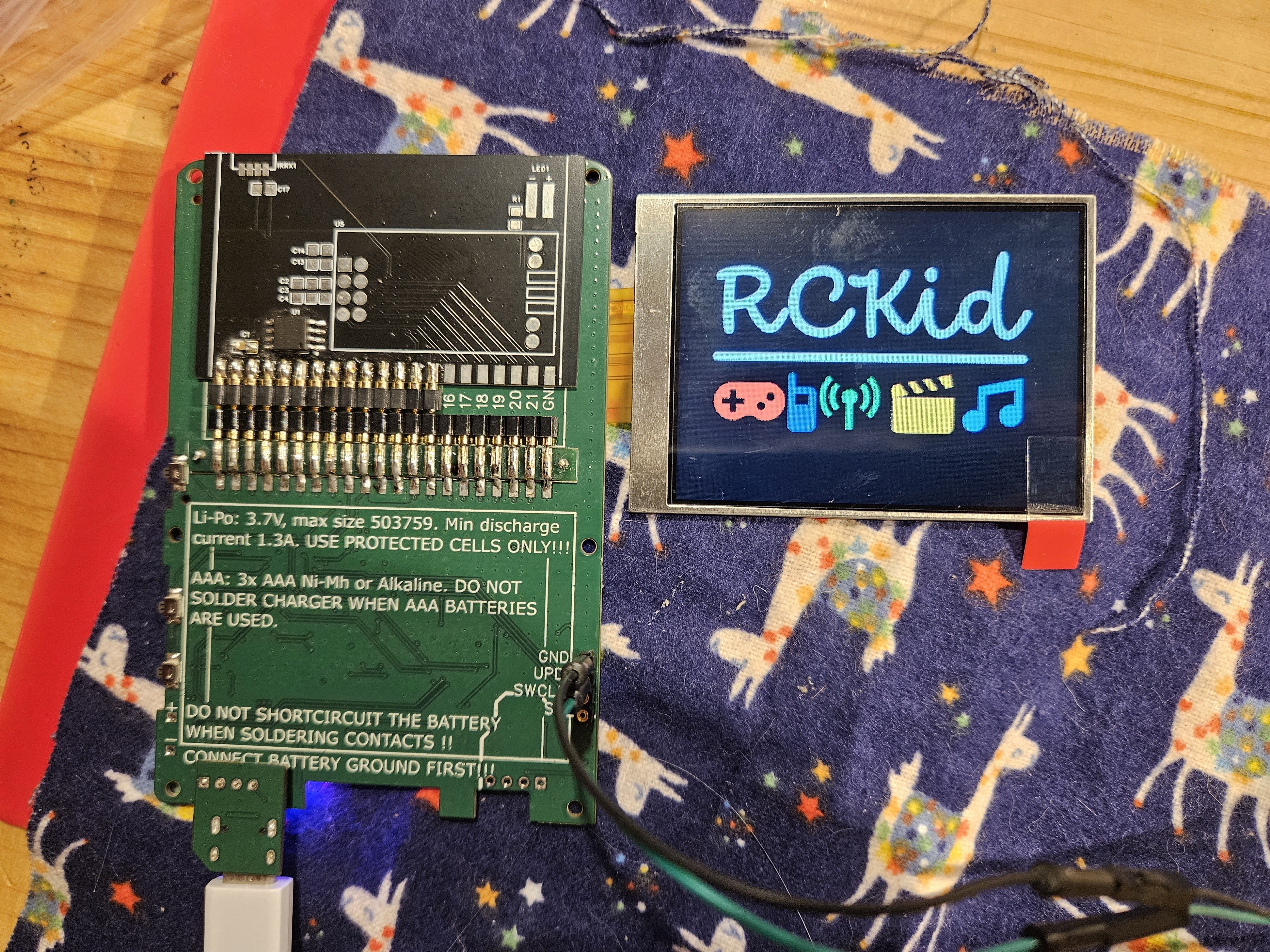
RCKid
The first truly personal device for kids — designed to grow with them from drawing sprites to writing C++