 Zduka
ZdukaPast few weeks I have been busy with yet another almost final revision of RCKid, 3.2, codename Beaver King (from now all versions will have names based on currently favourite animals of my kids as they get super excited when they see the names written on the boards). Below are shots of the final PCB - presented here in beautiful black & ENIG finish that I plan for the more bulkier orders later on. This one will be the boring green & HASL for cost savings though:)
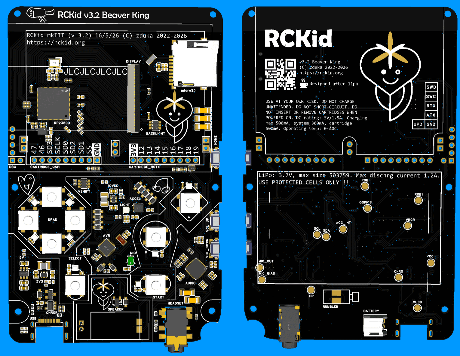
The version incorporates the lessons learned from building the SDK 1.0, some cost saving decisions and hopefully a lot of DFM improvements, namely:
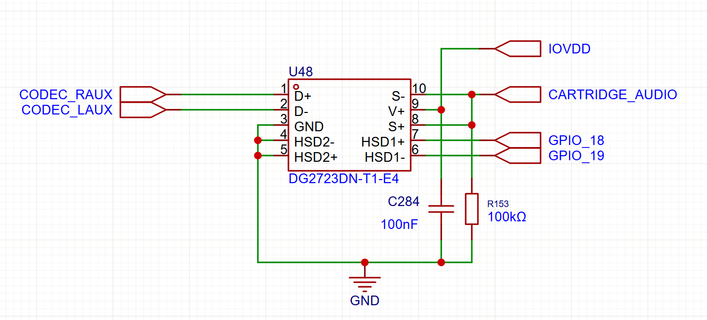
- the FM radio is gone. It can return in the cartridges, where fundamentally it belongs better. It simplifies the assembly process by not having to worry about the antenna placement, makes the BOM much easier (this was the only part that was not available directly from JLCPCB) and makes the audio design much cleaner because of the extra space I gain there. It clears one pin on the RP2350, which I put to use immediately in the analog/digital demux switch for cartridge pins (see below)
- I am taking a bold step and making my own speaker enclosure. Previously I have used an already enclosed speaker from Samesky with wires that I had to solder manually. Now I am using non-enclosed speaker with spring contacts for much easier assembly, which is great. But I have to make the enclosure for it. The idea is that natural enclosure forms between the PCB and the top plate (you can see its outline in the image above on the PCB). I am not yet sure about the quality of the seal this will make, but I reckon its worth a try. The new speaker is cheaper, and louder, according to the datasheet.
- I am changing buttons too: the side buttons which I had to solder manually to the bottom side are replaced with sinking ones that are larger, better centered (the actuators are actually close to the middle of the buttons) and will be soldered by JLCPCB. For the top buttons, I have used the super thin ones, without plungers, but making the plungers on the buttons themselves proved very difficult. Also I did not like the feeling. So now I switched to buttons with integrated silicone plungers, hoping that this would simplify the mechanical tolerances, and hence assembly complexity for the buttons
- I have replaced rumbler motor with one that uses spring contacts as well and will sit under the PCB for yet simpler assembly
- I have also changed the battery connector - I have found that I can buy the batteries I need with JST-PH connector as well, which is just large enough to fit under the PCB, and at the same time I am trying even different option where a special daughterboard with spring contacts will be soldered to the battery wires, making the assembly even simpler (I am scared that the battery wire will get squished when I close the PCB on the JST-PH connector and without transparent cases, there is no way to tell
Five things were changed electrically:
- LTR-390UV sensor for ambient light & sun detection. There was free room on the PCB, I already have the chips purchased back from mkII so no extra cost, and my hope is that the light detector will allow me to do very crude wireless transmission between two devices by blinking the display white opposite to the light sensor so that kids can exchange tiny pieces of information this way.
- with the FM radio removes, I have added analog multiplexers & control line to two of the cartridge pins. These can now be used either as digital pins, or can be used as analog inputs to the audio codec (where the FM radio previously connected). This means cartridges can provide extra audio HW with ease (such as the FM radio:)
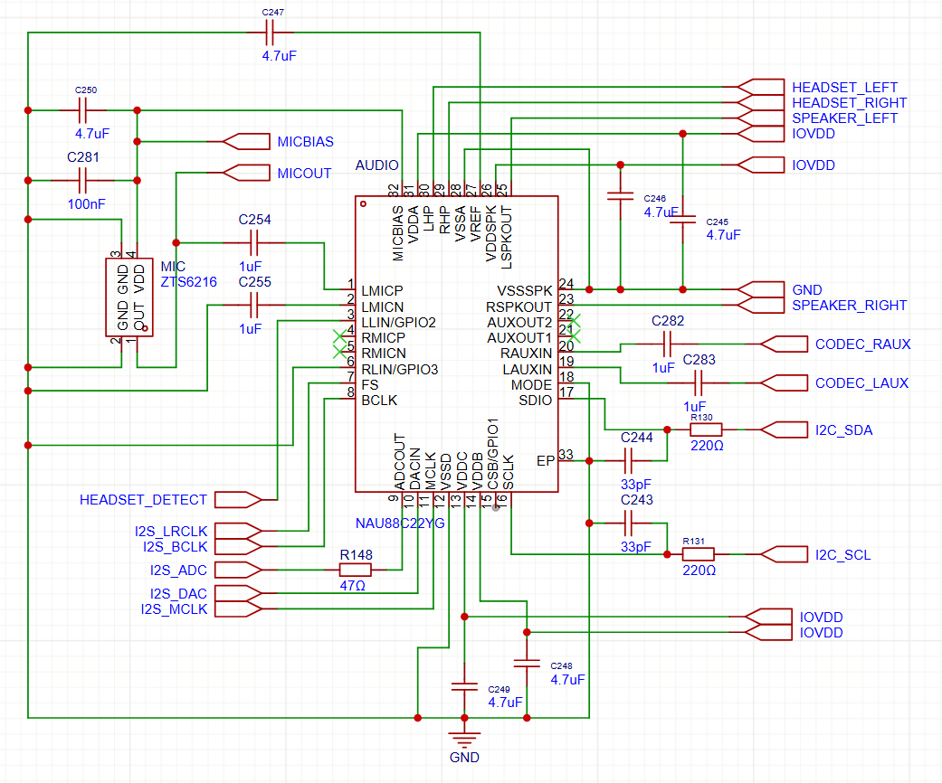
- previously the board had electret microphone, but they did not work. I have tried everything to make them work, but to no avail. This time I am switching to MEMS microphone hoping this would solve the problems.
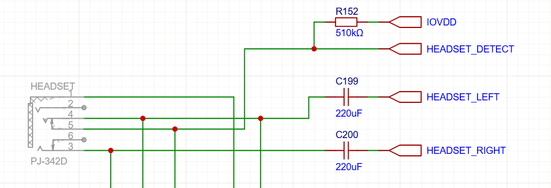
- instead of double ground connection, the headphone detection circuit has been reworked to use the integrated tip switch in the jack connector. This should allow me to detect even headsets with microphones reliably (previously this was flaky, I suspect because the microphone on the second ground ring changed the signal electrically to sometimes fall outside of the reliable high-low region)
- AVR and RP2350 are no longer connected with interrupt line (it was not used in the past). Instead those pins go to the now larger debug connector and are UART TX for both chips, which should ease debugging a lot
I have also reworked the case a bit - first room had to be made for the new components (speaker case, rumbler, battery connectors), but then I am also adding a slight curved rim to the top (see the incomplete picture below for the difference). The transparent SLA prints look very nice, but are very, very brittle, both of my kids managed to chip theirs already. So current plan is to print the back cover from nylon and the extra curved rim will protect the clear front case similarly to how phone protectors work.
That's it. I am running latest visual changes now and then letting the design sink a bit as usual in case I have forgotten something very important. Then in about a week, I am ordering the boards:) So wish me good luck, and if you happen to spot a mistake in the circuits above (especially the microphone which I am the least sure about), please, please, let me know:) Thanks!
Discussions
Become a Hackaday.io Member
Create an account to leave a comment. Already have an account? Log In.