A controller for all your IoT needs.
To make the experience fit your profile, pick a username and tell us what interests you.
We found and based on your interests.
ESP_IoT_Controller_v2.zipGerber files, updated silkscreenZip Archive - 201.80 kB - 06/11/2017 at 10:01 |
|
|
schematic.pdfupdated versionAdobe Portable Document Format - 61.33 kB - 05/07/2017 at 12:09 |
|
|
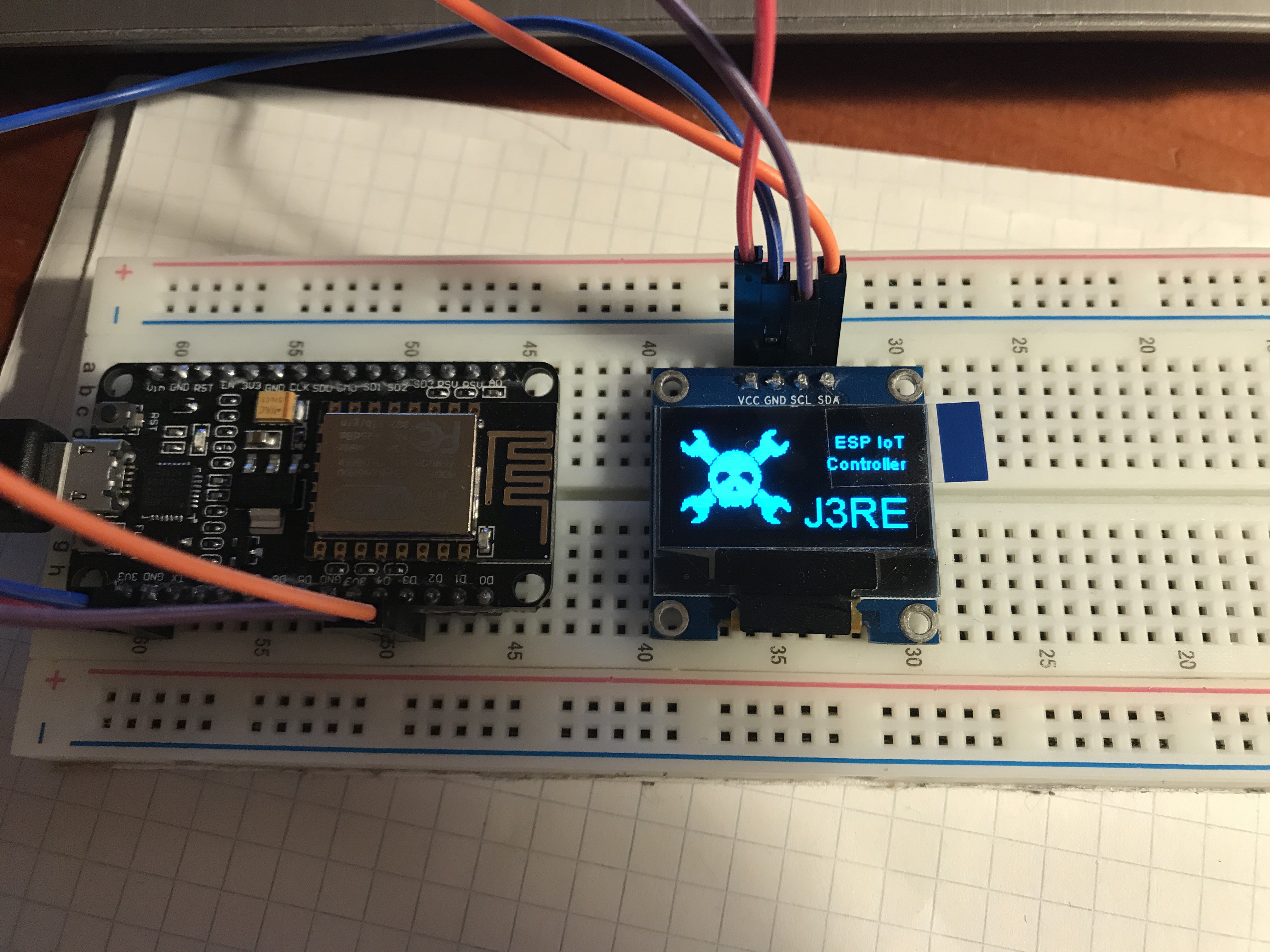
I have now ordered the OLEDs from three different vendors. Two of three times they had the "right" pinout (the pinout I used for the PCB design). The other time the VCC and GND pins were swapped. On the first picture you can see how I fixed this problem.
The last displays I have ordered, came in these nice cases. I have to build a project which fits in there. (thinking of an ATtiny and a coin cell, ...)
I combined spacehuhn's deauther and packet monitor programs into one program and changed a few things, now the program runs on my controller.
I can switch between the two modes by pressing left and right
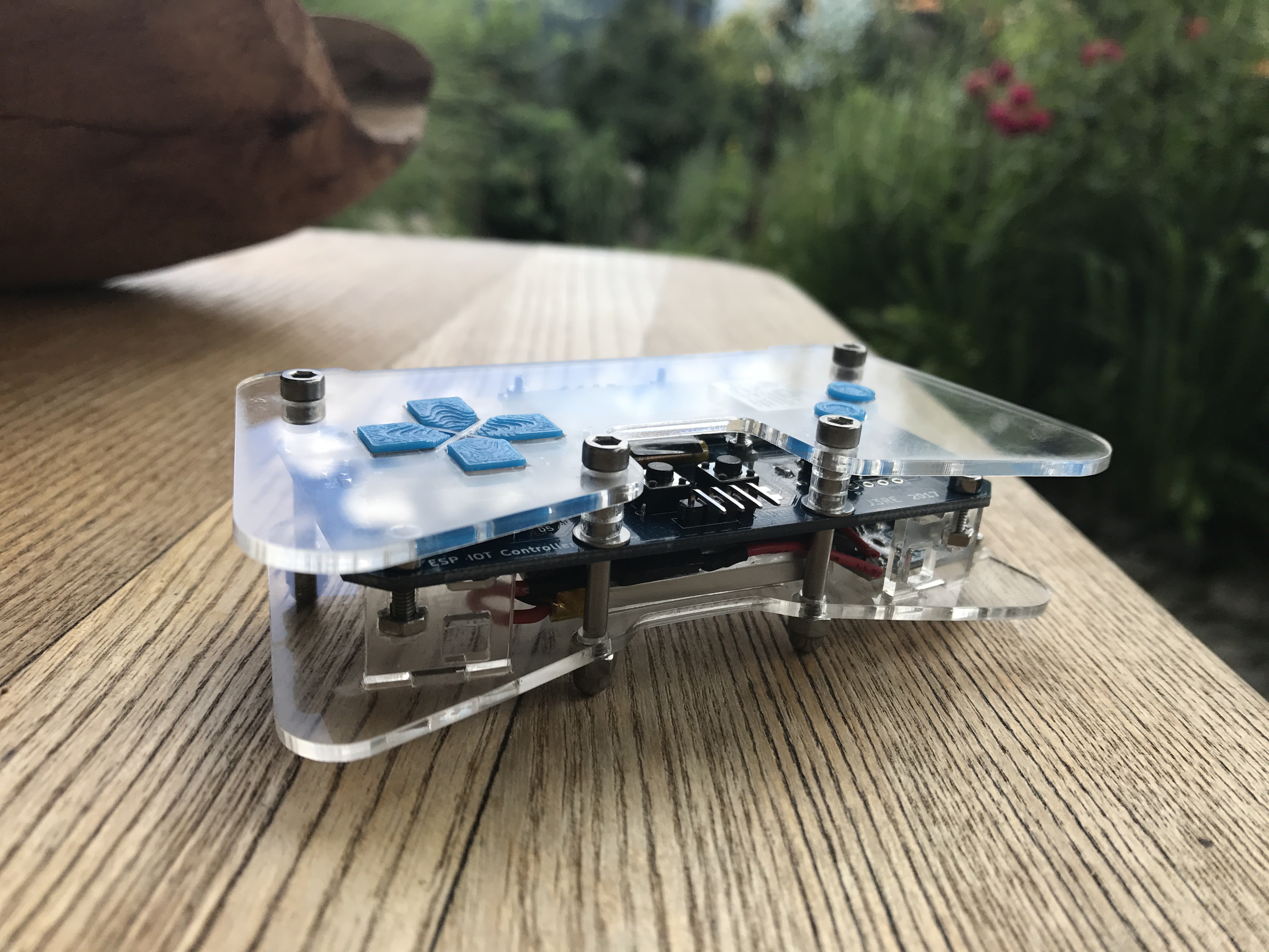
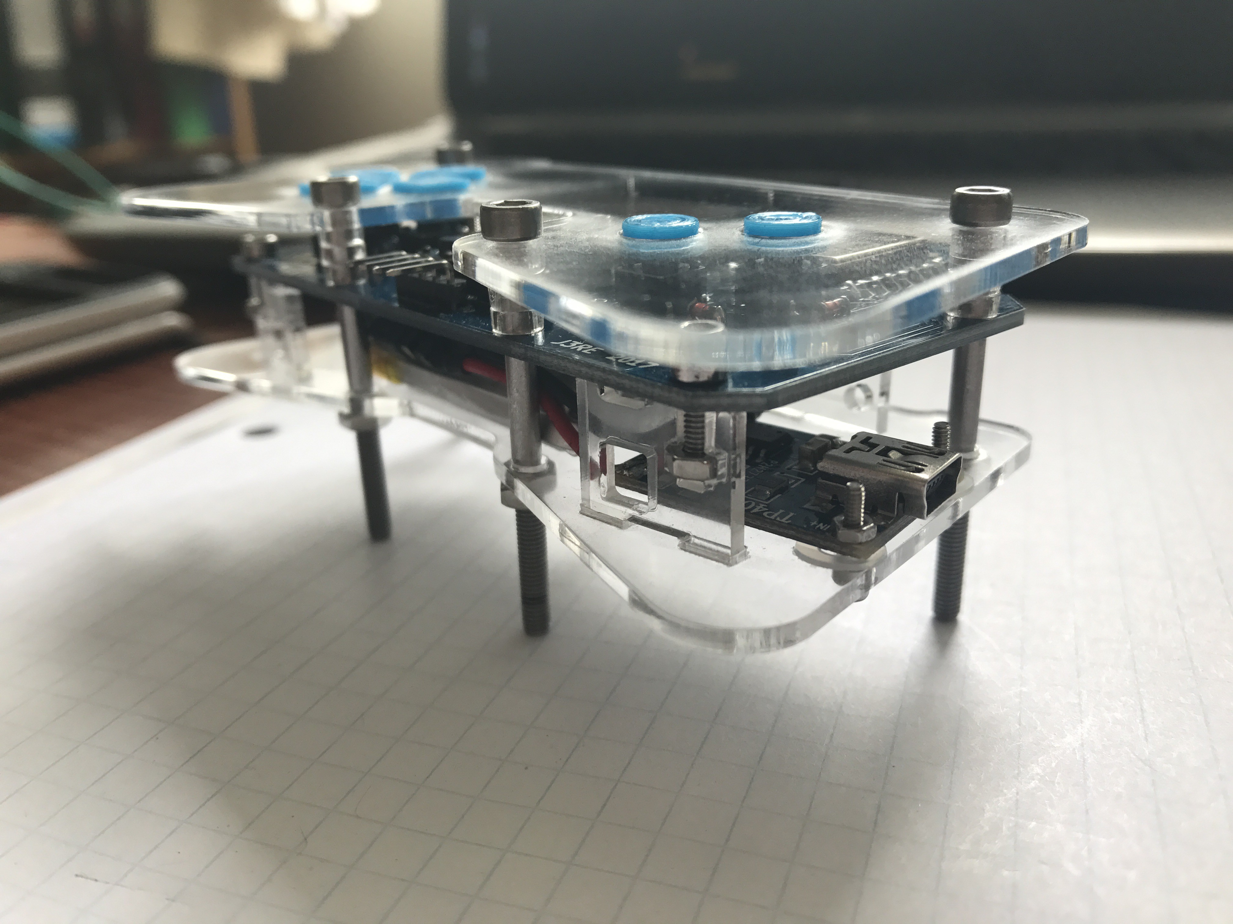
I finally had access to a metal saw, so I cut the screws to the right length and screwed on some cap nuts.
I made a short demo video how I use the controller to interact with my smartHome. It was a bit difficult to get the right exposure on the OLED display, but I think it is readable.
I also received ~12€ from the "Hackaday Prize Seed Funding" a few days ago. A big thanks to Hackaday and the Hackaday community. I used the money to buy Andrew "bunnie" Huangs new book "The Hardware Hacker".
I soldered the PCB and assembled all the parts. I still need to cut the screws to the right length, but apart from that the hardware is finished. The PCB is functional, but there are some things I would change next time. For instance:
I will make an example code, which shows how to use the buttons and control the LEDs. The code should be on github in a week or so.
PS: If someone near to Austria wants a PCB, drop me a line, I don't need all of them.
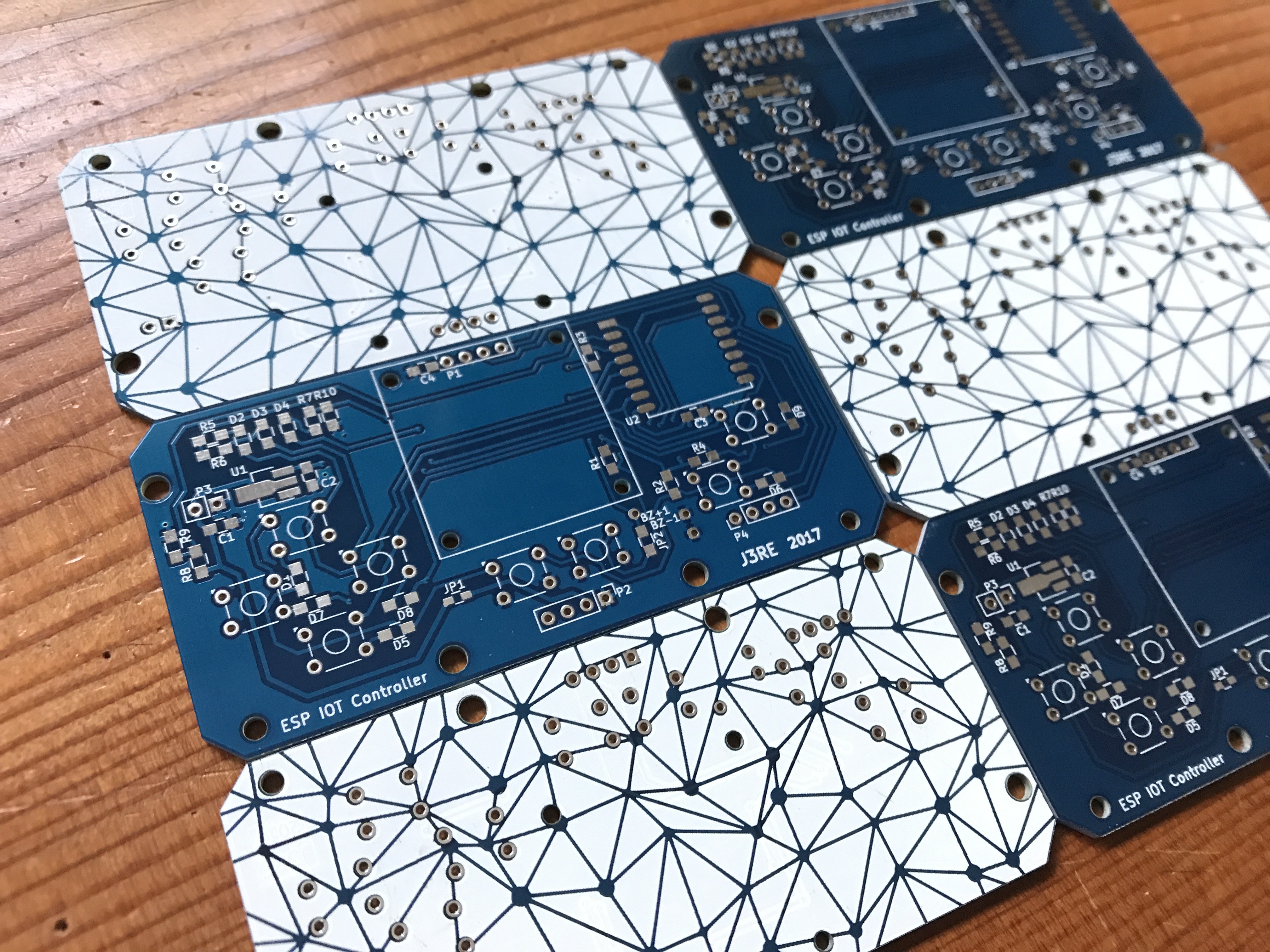
The PCBs arrived yesterday, 16 days after ordering them. Impressive.
Unfortunately I am not in my apartment until sunday evening. Maybe I have enough time to solder the board next week.
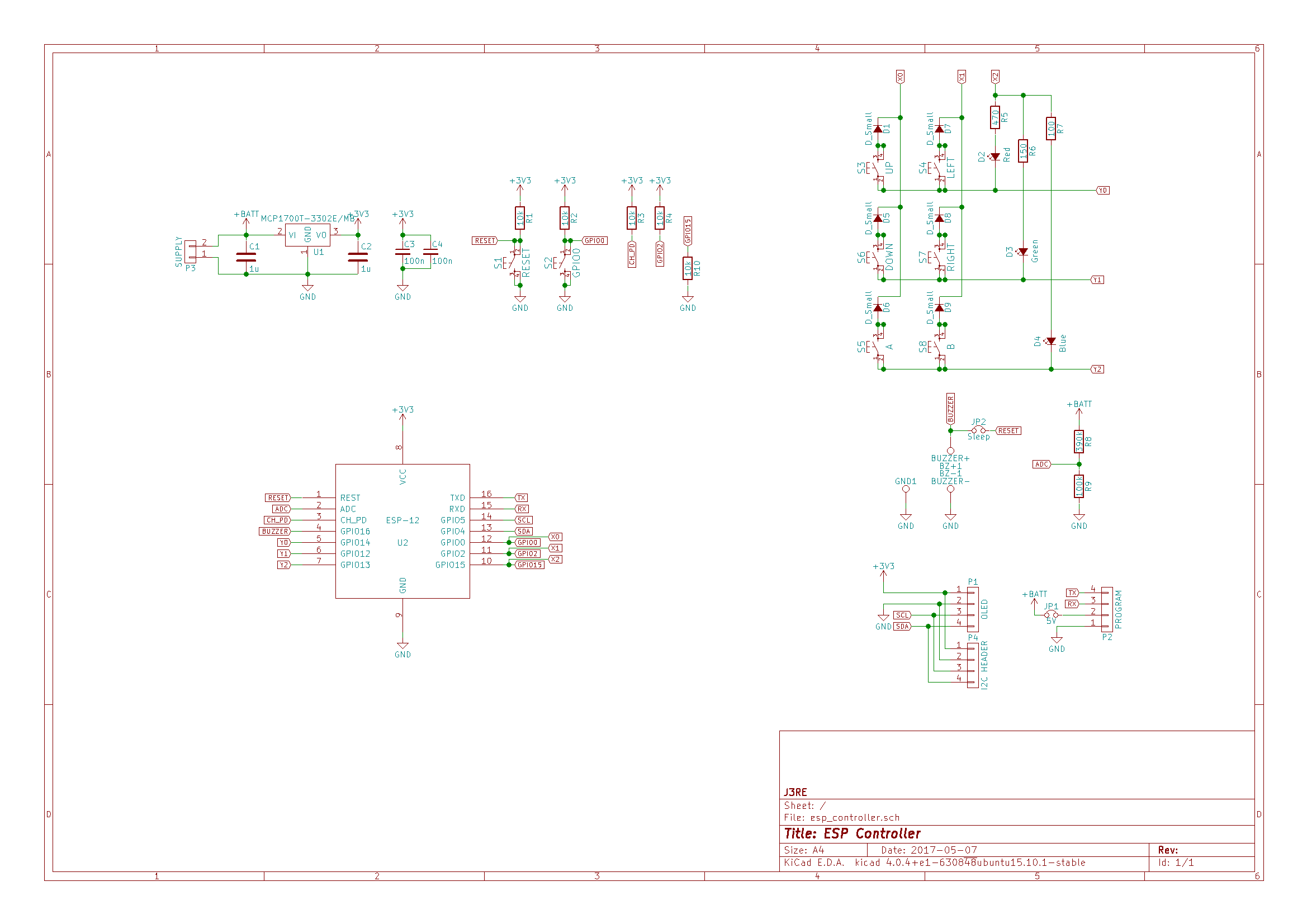
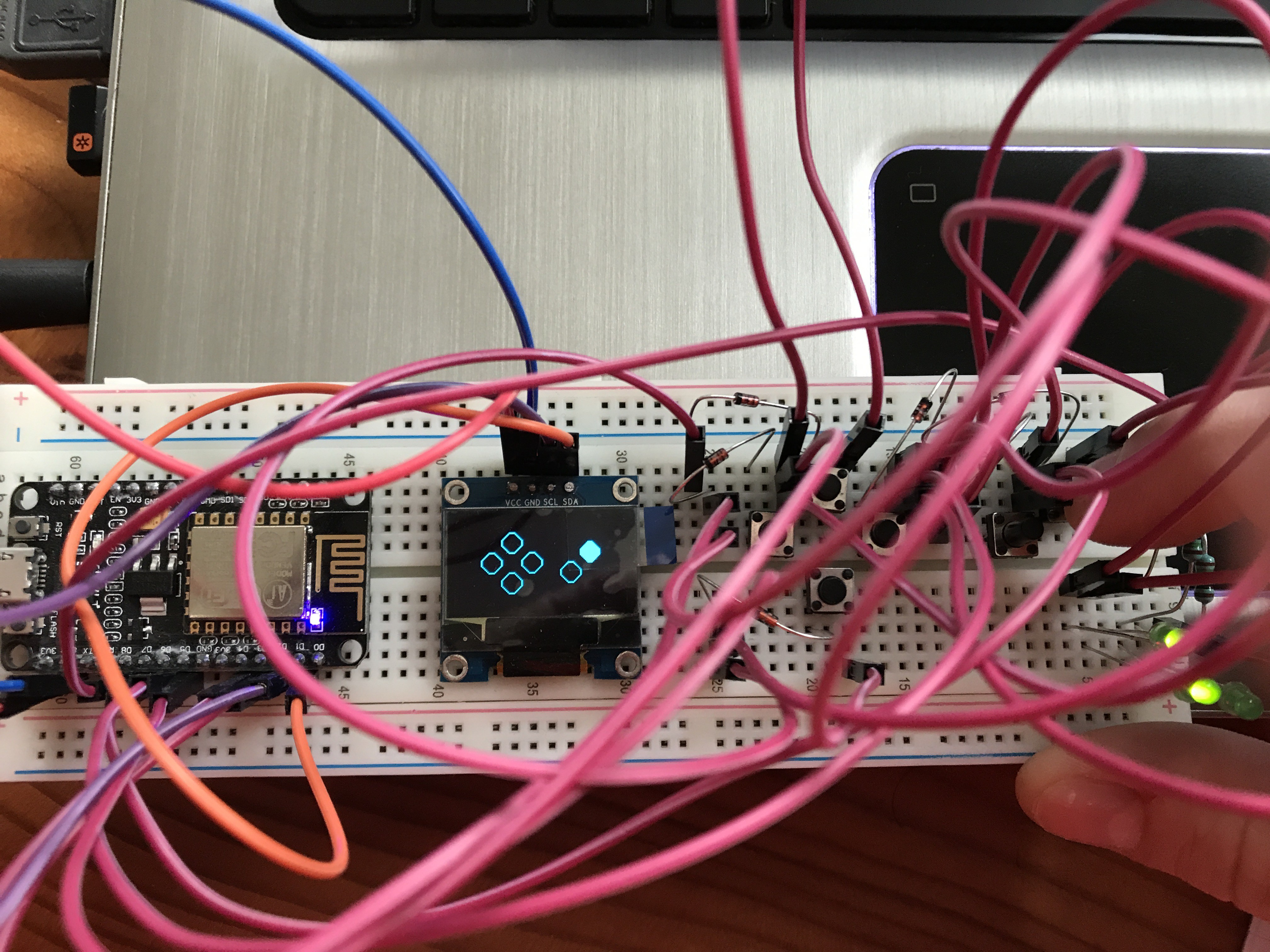
I have added a diode to every button. Now I can detect more than 2 simultaneous button presses.
The circuit works pretty well on the breadboard. The multiplexed LEDs are flickering, but I think I can fix this in software.
I also ordered the PCB today, it should be here in a month or so.
The PCB-Mill still needs some software tweaks, so I may get them manufactured at a PCB house and try the mill at my next project.
Meanwhile I started writing a test program. For testing I use a NodeMCU board. I use this nice library by squix to communicate with the OLED.
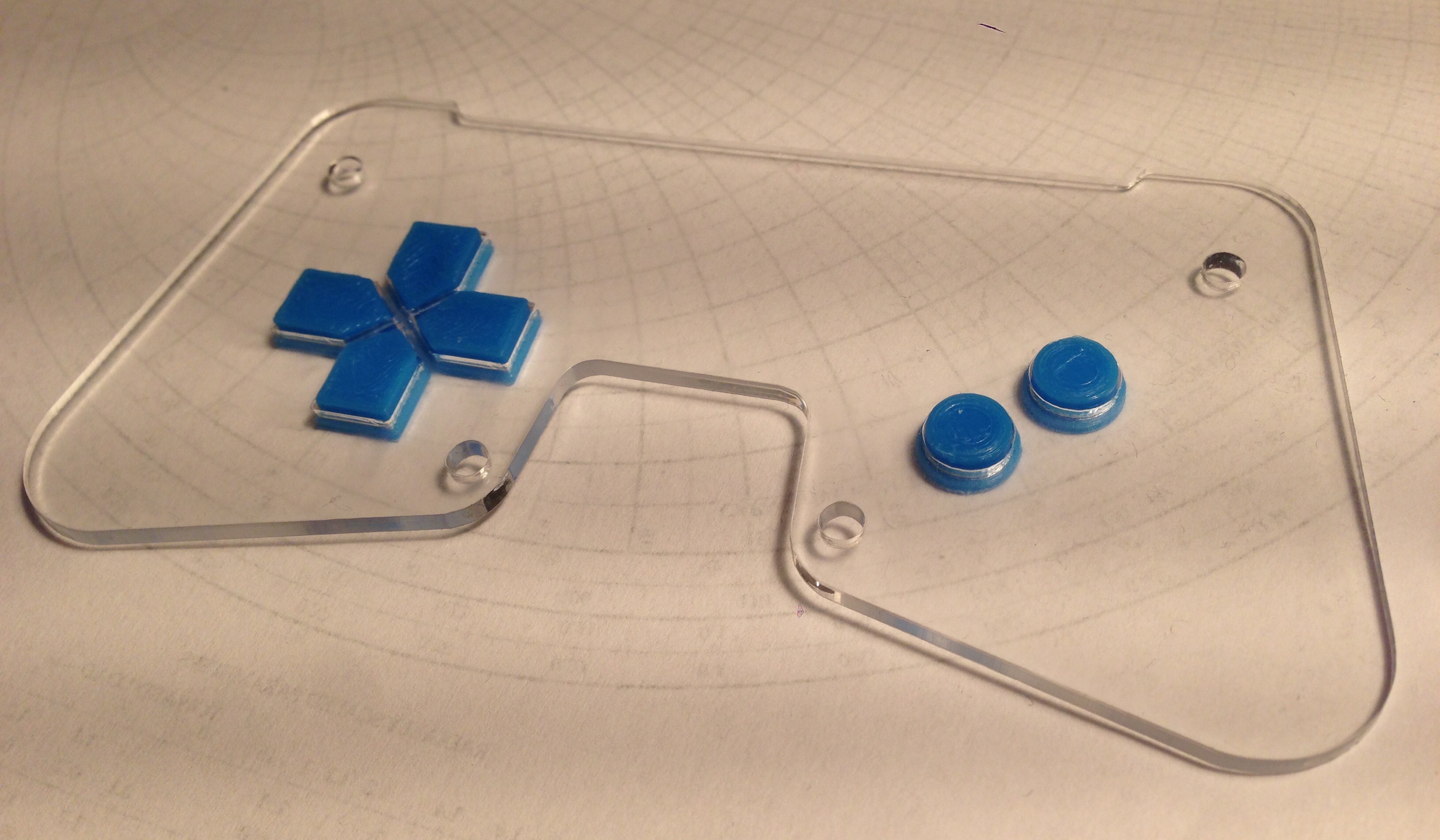
Today I printed the buttons for the controller. The surface finish isn't that beautiful, but they fit nicely into the top acrylic plate.
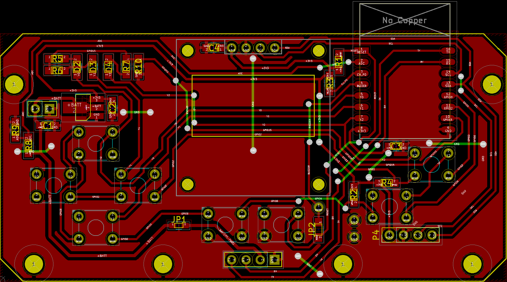
I have access to a small CNC-Milling machine. Therefore I designed an 1-layer board with relative thick traces 0.4mm (15.75 mils). I wasn't able to route everything on the top layer, so I have to use some jumper wires for the bottom layer.
Create an account to leave a comment. Already have an account? Log In.
Diseño brutal! Además de la rapidez y funcionalidad que le das. Love it
I see you've achieved some design goals we have in common :) deauther and gamebuino are things I want to port to my #LAMEBOY - another ESP12 handheld project :)
Jeremias, your board looks awesome! Love the artwork!
What program did you use to render the model with the plexiglass case?
PS: Thanks for liking my Giant RGB LED Cube project.
Looking forward to seeing more details on this - looking to do something similar with my #GBAA: Game Boy Advance Arduino project!
Nice project, I like the cartridge concept. You could make IR, 433MHz or a GPS cartridges. I haven't much pins left to do something like this, I can only use the Rx/Tx pins for additional hardware.
Thanks man!
I was going to try and retain the cartridge reading to take them as the original, but on this version that is a step too far. I'm just going to breakout all my pins alongside 5v and ground pins to give plenty of options for expansion.
For your project you should look to breakout the i2c-capable pins on the ESP8266; then you can add multiple devices (other microcontrollers, i2c lcd screens, i2c expanders etc) to the same bus.
Great idea, I haven't thought about using more than one I2C-slave device.
Now I have added a breakout for the I2C-pins.
Become a member to follow this project and never miss any updates
 Bud Bennett
 Andrey Kalmatskiy
 C. Scott Ananian
 Julius
I wish to print the pcb with provided files, but I have never printed or used pcb making software, which 2 layer file inside the zipped folder should I be using to order printed pcbs? Thanks