Close
0%
0%

Simon Says PCB

A PCB project that uses a ESP32 C3 Supermini and a custom designed PCB to make the Simon Says game

Similar projects worth following
After learning how to design schematics and PCBs on Altium I wanted to take what I learned to make my very own PCB. I wanted to start small, and after searching the web for ideas on what a beginner PCB project would look like, I saw someone had recreated the Simon game with a microcontroller, buttons, LEDs, and their own custom PCB. I wanted to do the same with the hardware I have which is what this project is.

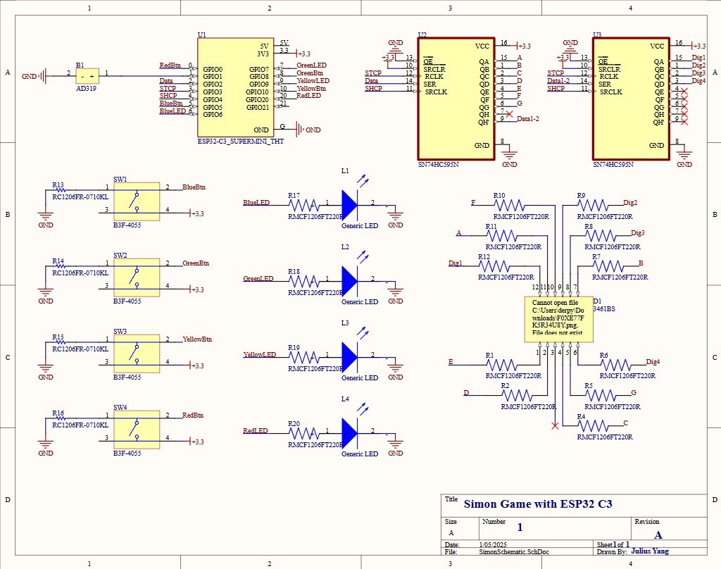
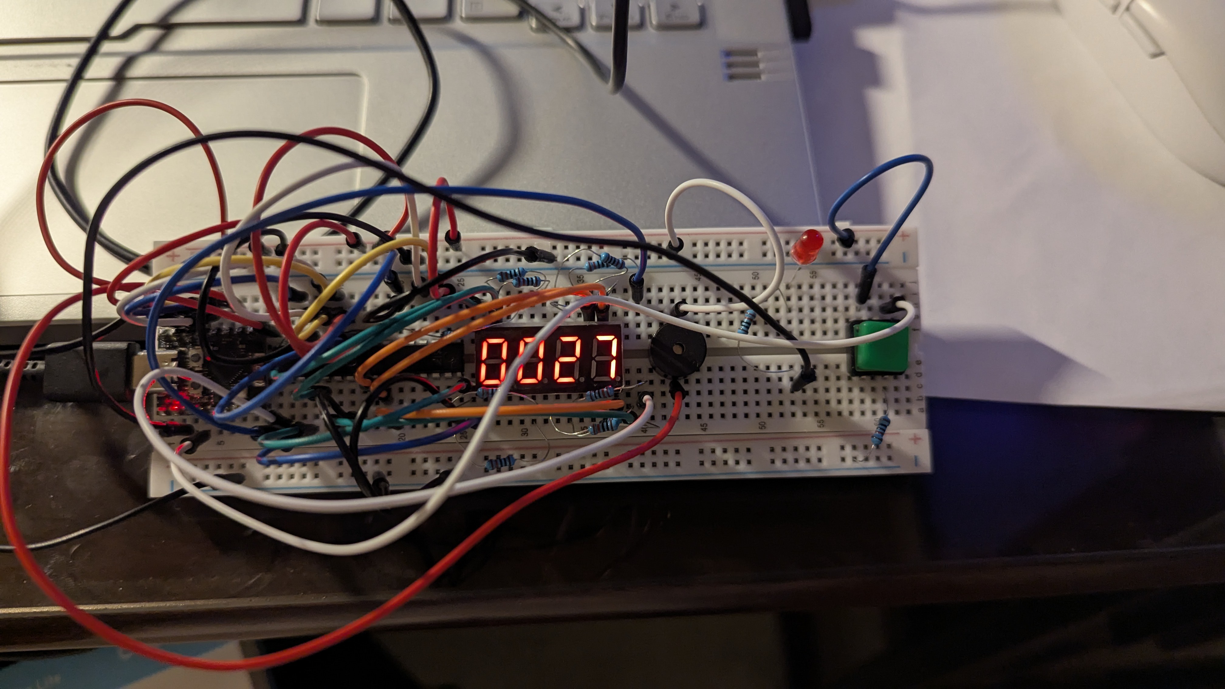
The Game: The Simon game is a very simple game that consists of 4 colored buttons, each with a corresponding LED. It is a memory game where the user is tested to see how many button presses they can memorize in a random sequence. So the computer will first light up one of the colored LEDs and the user has to repeat that color by pressing the corresponding button. Then the computer repeats that sequence, but this time adding another color (could be the same one) to the mix. The game keeps on going until the user fails to match the sequence the computer has generated.

Why?

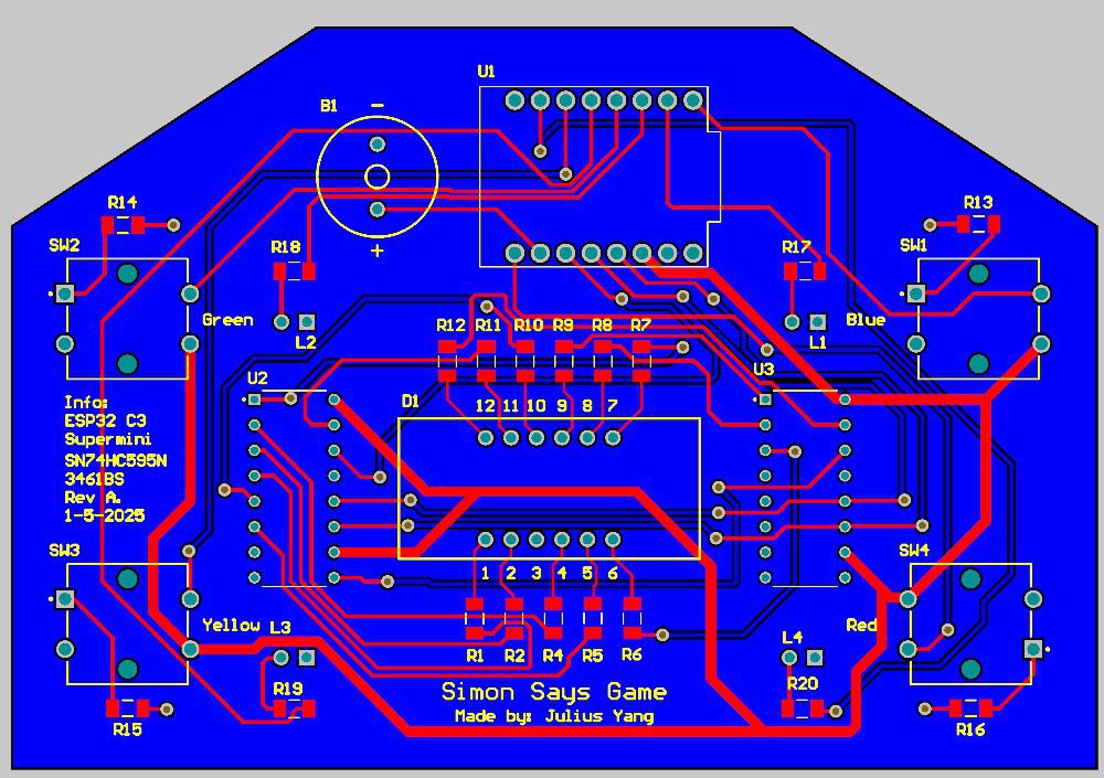
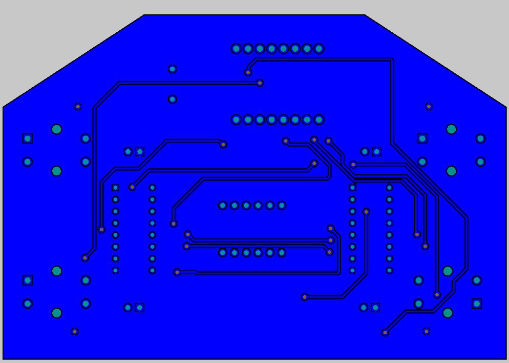
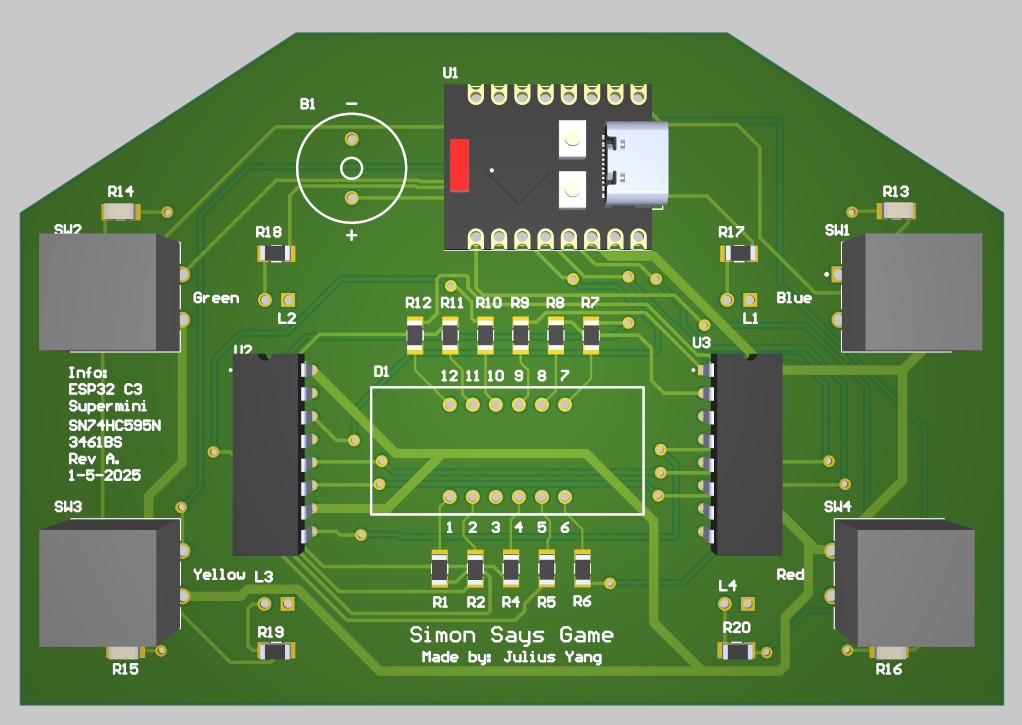
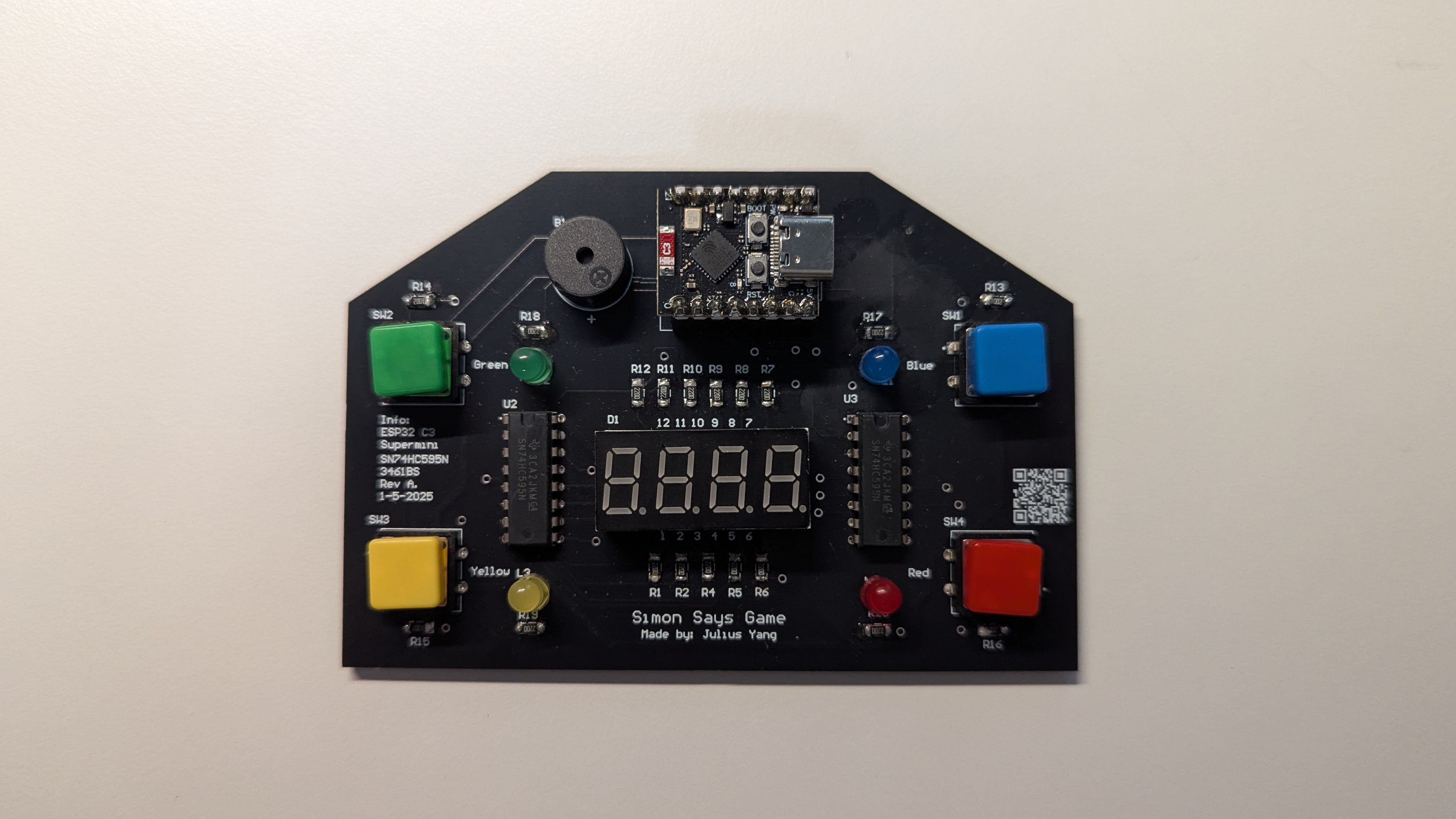
This is my first project where I decided to go through all stages of the PCB design process; from creating a schematic all the way to assembling the final PCB after it has been produced. I wanted to choose a project where the design would be extensive, but tame enough where I did not have to touch high current or high speed signals. I also happened to have a lot of the components needed for this project lying around and I thought it would be a good way to tie in my hardware and software skills.

This is my first hackaday project and one that I hope to document well to show my thought process and the lessons I will learn along the way!

Schematic PDF_[No Variations].pdf

Schematic PDF version

Adobe Portable Document Format - 207.73 kB - 02/13/2025 at 06:51

Preview

Gerber for SimonGamePCB.PcbDoc.zip

Gerber files

x-zip-compressed - 39.89 kB - 02/13/2025 at 06:51

Download

Assembly Drawings_[No Variations].pdf

Assembly Drawings, autogenerated by Altium

Adobe Portable Document Format - 137.08 kB - 02/13/2025 at 06:50

Preview

SimonGamePCB.PcbDoc

PCB placement and routing file for Altium

pcbdoc - 1.67 MB - 02/13/2025 at 06:49

Download

SimonSchematic.SchDoc

PCB schematic document for Altium

schdoc - 281.00 kB - 02/13/2025 at 06:49

Download

View all 6 files

  • Assembling the Board

    Julius02/13/2025 at 07:06 0 comments

    After exporting my project files and getting my PCB manufactured it finally came! I truly am astonished at how quickly we can go from project design to getting a physical PCB in hand; it only took me a week and a half and it was very affordable to get a custom PCB produced. 

    Now that I have all of my parts in hand and the PCB as well it is time to assemble it! The first thing I started off with was the SMD resistors. I used 1206 size SMD resistors since I was going to be hand soldering them to my board. To do that I first applied my solder to one end of the pad, soldered the resistor to that end, and finally soldered the other end once the resistor was secured. With so many resistors on my board (mainly for current protection), this process took me awhile to do.

    After soldering my resistors I soldered the rest of my through hole components. This part wasn't too bad, however I messed up when soldering my display. I forgot to check to see if the display was flat before I went ahead and soldered the rest of its pins. That was a grave mistake, because after hours of trying to desolder and manipulate the pins so that the display lie flat, I could not get it to budge. Another issue I noticed was that most of my through hole pads were too narrow; I should have increased the pad sizes. Although I was still able to secure all of my components, it did make the tolerances for soldering much tighter than they should've been. For my ESP-32 I did not want it to be a permanent fixture to the PCB, so I used some male to female header pins and soldered them in place instead. Here's the final result of the finished PCB!

    The finished PCB!

    My next step is to finish coding and upload my final code to the ESP-32

  • Designing the PCB

    Julius02/13/2025 at 06:44 0 comments

    Creating the Schematic

    After prototyping everything on Wokwi and confirming it with a simple test circuit I moved on to create a schematic of the circuit in Altium Designer. First was to find footprints to represent all of the components I have in the circuit. For some, like the 74hc595 shift register I was using, it was very easy to find symbols, footprints, and their corresponding 3D model. However, for other components I could not find any of this information, so I had to create my own components using the dimensions from their datasheets. After creating the components, I wired them up on the schematic, double-checking to ensure that I did not miss a component and did not mess up on the wiring. This is the final result of that schematic:

    Schematic For PCB

    PCB Design

    After wiring my components on the schematic, it was time to turn that design into a PCB! Altium associates all of the schematic symbols with their PCB footprint, so when transitioning to part placement all of their footprints, along with their nets transferred over. 

    An important part of my design was that I wanted the PCB to be easy to hold, and easy for the player to use. Since the game requires the player to constantly press buttons, I wanted to place them so that their thumbs would not be obstructed by a component. That's my reasoning for the decision to place the 4 buttons on the edges of the PCB, 2 on each side. Since the buttons were going to be on the side I wanted to place all of the other components towards the center of the board. The buzzer and ESP32 reside on the top edge, moving the larger components away from the screen and the buttons. As for size, I definitely could have made it much smaller, but for ease of assembly and use I decided that a board roughly 3"x4" would be a good size. 

    PCB with all layers shown

    Since my board is a 2-layer PCB I did the standard top layer for signals, and bottom layer for the ground plane. If my signals had to cross one another, I used a via and routed the signal on the bottom layer, ensuring that a channel was created for it through the ground plane. For the most part I used the same trace widths except for the 3.3V line which was wider than all of the other traces. I probably could have gotten away with a narrower trace, but since this was the power line I wanted to ensure that there was enough current to power all of my components.

    Bottom Layer

    After all of the placement and routing this is what the final PCB looks like on Altium! All there is to do is to order my components and to fabricate the PCB

    3D View of PCB

    This was done between January 3, 2025 and January 5, 2025

  • Starting Off

    Julius02/10/2025 at 09:43 0 comments

    When thinking about what I needed for this project I determined I needed: a microcontroller, a display, 4 buttons, 4 LEDs, and resistors. It happened that I had all of those things in one form or another in the kit I already had at home. 

    For the microcontroller I decided to go with the ESP32-C3 Supermini I had because it was a super small chip that was very capable. Not only does it have 11 GPIO pins which is just short of the 10 I needed; it has Wi-Fi, Bluetooth, and a very capable processor. This will give me the room to do more with this project in the future.

    Large, zoomable image of ESP32-C3 Development Board ESP32 SuperMini WiFi Bluetooth Mini Module. 2 of 8

    For the display I originally wanted to go with two 1 digit seven segment displays so I can show scores from 0-99. However, I started to realize the wiring can get very complicated and the 2 displays would actually take up a decent amount of space on the PCB. Instead I went with a four digit seven segment display with the same number of pins as a single digit display. It also wasn't too small and it seemed doable with 2 shift registers, which are used to drive the display.

    It was easy to find the rest of the components, I had LEDs with 4 different colors, 4 buttons, and a plethora of different resistors so it was onto building the circuit on a simulator.

    Simulating And Prototyping

    To simulate to test what I wanted to do was feasible or not I used the ESP32 Simulator called Wokwi. Their platform allows me to wire up components to an ESP32 and verify whether or not my circuit works. The best part of the simulator is that I can upload my C code and it will simulate how the microcontroller interacts with the rest of the circuit.

    Learning About 7 Segment Displays

    I did the simulation in a few stages, especially since I did not know how to use seven segment displays. So I first started off by wiring up a 1 digit display and testing it to learn how they work. I found out that I can use a shift register to write to these displays by shifting data (or in this case electrical signals) out to the correct pins of the display to light up the segments that need to be lit. Another video (LINK VIDEO HERE) taught me how to utilize 2 shift registers which is what I ended up going with to drive the 4 digit display. I was able to confirm that this was possible with the wiring I wanted for the PCB and that my code was able to drive the display correctly.

    After verifying the simulation I then went to create a prototype using the wiring and code from the simulation. I was super worried when my display was not showing the digits correctly at first, segments that were lit weren't supposed to be on. However, it turned out to be 2 wires that were in the wrong position and I got the display to work. My prototype just increments the counter every second and to see it work was a relief.

    Connecting Everything Else

    Once I got my display working I started to wire up the buttons, resistors, LEDs, and a buzzer that I decided to include to add audio. I wrote up code that would increment a counter by 1 whenever a button is pressed. The LED corresponding to the button's color will light up, and the display will show the count every single time. I did not want to create the full Simon game just yet; I wanted to first check that my wiring was correct and that all of my components were able to work with each other.

    Prototyping

    Now that the simulation is done I needed to test my circuit by building it out in the real world. Since I was limited by the size of my breadboard, I decided to connect everything but 3 sets of buttons and LEDs. I just wanted to verify that the button can trigger a sound to play on the buzzer and then change the display. I uploaded the same code I wrote onto my ESP32 and it worked just how I intended it to. Now that the wiring was verified and I knew there was a path forward to making the full game I went onto coding the full game.

    All of this was done between December 30, 2024 and January 3, 2025

View all 3 project logs

Enjoy this project?

Share

Discussions

Similar Projects

Does this project spark your interest?

Become a member to follow this project and never miss any updates