 Aula Jazmati

Things Used
Hardware
- ACEBOTT ESP32 Smart Home Edu Kit – Level 2 (QE024)
- ESP32 Controller Board
- I2C 1602 LCD Module
- Ultrasonic Sensor (HC‑SR04)
- Servo Motor SG90
- Passive Buzzer Module
- Acrylic structural parts (feeder frame, hopper, etc.)
- Jumper wires (included)
- Pet food bowl
- A small container for food storage (optional)
Software
- ACECode (Scratch‑based) OR Arduino IDE
Understanding the Components
1. I2C 1602 LCD Module
This display shows 16 characters per line, 2 lines. It uses I2C communication, so only 4 wires are needed (VCC, GND, SDA, SCL). We'll use it to display the running timer (hours:minutes:seconds) and the feeding status (“off” or “on”).
Pinout:
- V: Connect to 5V
- G: Connect to GND
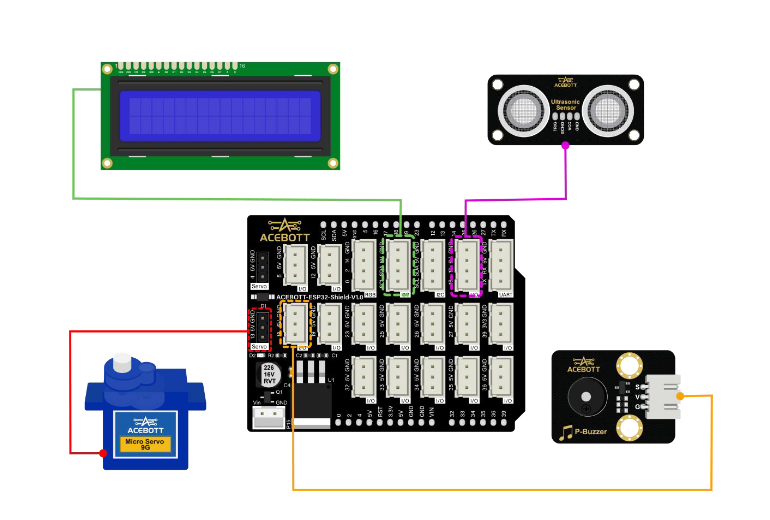
- SDA: Connect to GPIO21 (I2C data)
- SCL: Connect to GPIO22 (I2C clock)
2. Ultrasonic Sensor (HC‑SR04)
This sensor measures distance by sending a sound pulse and measuring the echo return time. It detects when your pet is in front of the feeder. Only when the pet is near (distance ≤ 10 cm in our code) will the food be released – no stale food sitting in the bowl.
Pinout:
- VCC: Connect to 5V
- GND: Connect to GND
- TRIG: Connect to GPIO16 (or any digital pin)
- ECHO: Connect to GPIO17 (or any digital pin)
3. Servo Motor (SG90)
The servo rotates a small gate or lever inside the food hopper, releasing a portion of kibble into the bowl. In our code, it sweeps from 0° to 120° and back to 0° to ensure a good flow.
Pinout:
- Orange/Yellow: Signal – connect to GPIO13
- Red: Connect to 5V
- Brown/Black: Connect to GND
4. Passive Buzzer
The buzzer sounds after the food is dispensed to signal the end of the meal. This lets your pet know that feeding is complete.
Pinout:
- S: Connect to GPIO18 (or any digital PWM pin)
- V: Connect to 5V
- G: Connect to GND
Assembly
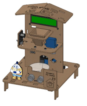
Follow the kit's official Assemble documentation – Level 2 for detailed visuals. Here's a summary:
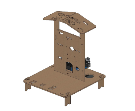
Step 1: Build the Feeder Frame
Assemble the acrylic pieces that will hold the food hopper, the servo, and the ultrasonic sensor. Typically, the servo is mounted under the hopper, with a small gate that opens when the servo rotates.
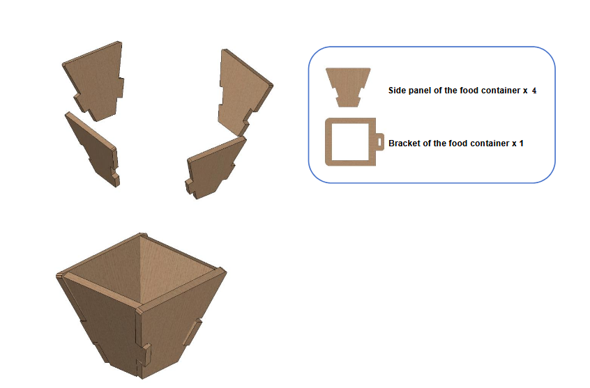
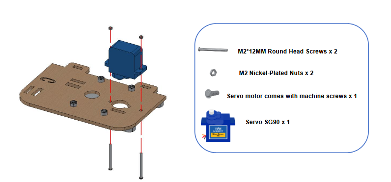
Step 2: Install the Servo
Mount the servo into its designated slot. Attach a small lever or arm that will block/release the food.
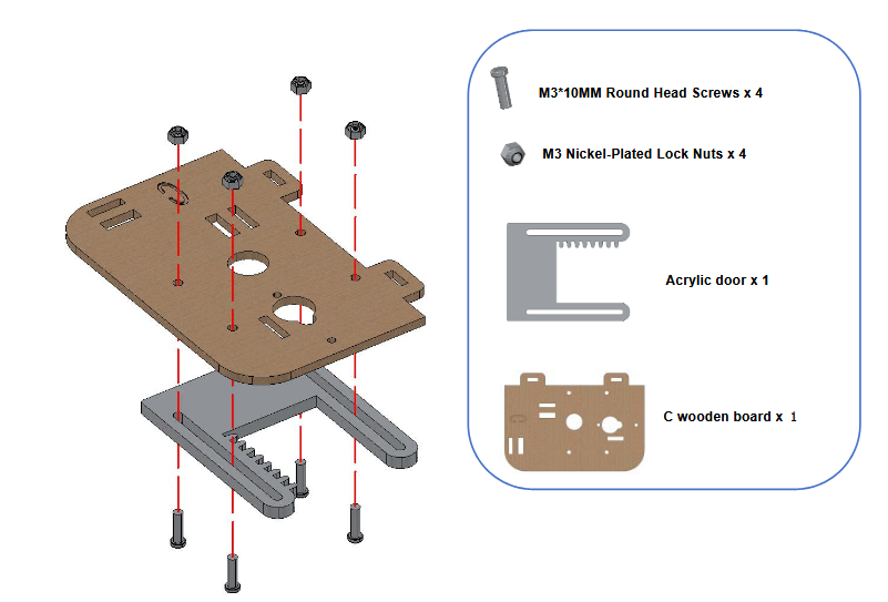
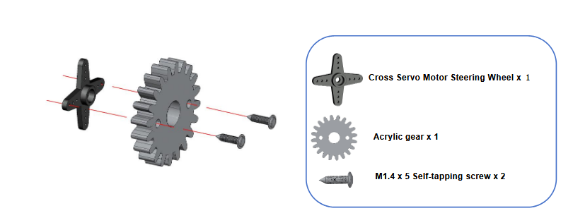
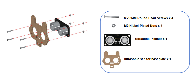
Step 3: Install the Ultrasonic Sensor
Place the sensor facing forward, at a height where it can detect your pet when it approaches.
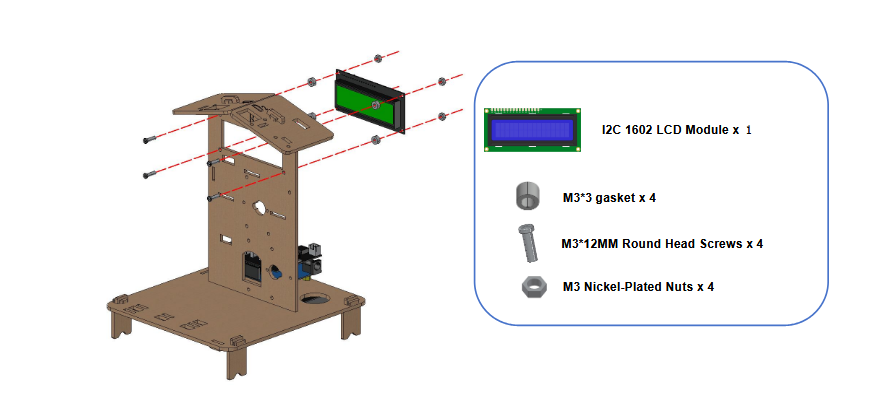
Step 4: Install the I2C LCD
Mount the LCD on the front panel of the feeder for easy visibility.
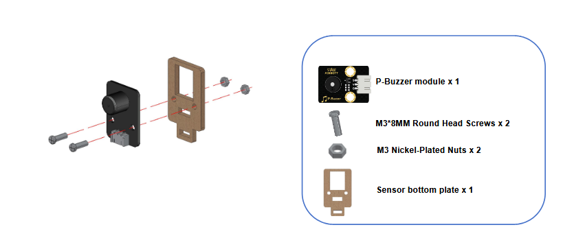
Step 5: Install the Buzzer
Place the buzzer module on the top or side so the sound can be heard clearly.
Step 6: Connect All Wires
Follow the wiring diagram.
Step 7: Add the Food Bowl
Place a bowl under the food outlet.
Code
Logic Overview
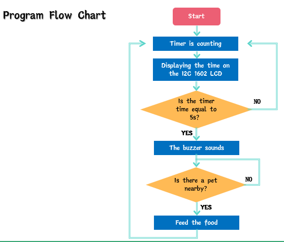
- Timer starts – the program records the elapsed time since startup.
- LCD displays the running timer (hours:minutes:seconds) and “Feeding: off”.
- When the timer reaches 5 seconds (adjustable), the timer resets to 0.
- The system waits until the ultrasonic sensor detects a distance ≤ 10 cm (pet is near).
- The LCD status changes to “Feeding: on”.
- The servo sweeps from 0° to 120° and back to 0° to open and close the food gate, dispensing food.
- After dispensing, the buzzer sounds for 1 second to signal the end of the meal.
- The system returns to counting time and waiting for the next interval.
Calibration & Testing
1. Ultrasonic Sensor Test
Upload a simple sketch that prints the distance to Serial Monitor. Make sure it reads correctly when you place your hand (or your pet) in front of the sensor. Adjust the threshold in the code (currently myUltrasonic.Ranging() > 10) to suit your pet’s size and the desired proximity.
2. Servo Angle Test
Find the correct angles to open and close the food gate. You might need to adjust the sweep range (0° to 120°) to match your mechanical design.
3. Buzzer Test
Verify that the buzzer produces a clear tone when tone(buzzer, 800) is called....
 Richard Deininger
 junkotron
 ROFLhoff
 Owen
Owen