 grecotron
The VGA History
The VGA standard and its corresponding controller were developed by IBM in 1987 and within the following three years it dominated the market of IBM-compatible computers. It supported a resolution of 640x480 with 16 colors and used a 15-pin input interface.
The standard was largely based on the older and well-established NTSC analog television standard, retaining many technical characteristics in order to facilitate the creation of VGA-to-TV converters. It maintained the same vertical resolution of 525 horizontal lines, of which only 480 are visible, while it chose a horizontal scanning frequency of 31.469 kHz, exactly double that of the NTSC standard.
Its operating principle is based on the serial scanning of the screen, line by line (from left to right, from top to bottom). For proper synchronization with the display, two synchronization signals are generated, whose active portion is at a logical low level:
- The horizontal synchronization pulse (HSYNC), which is activated at the beginning of each line
- The vertical synchronization pulse (VSYNC), which is activated at the end of each frame to restart scanning from the top of the screen
In addition, it produces three analog signals with levels ranging from 0 V up to 0.7 V, corresponding to the RGB (Red, Green, Blue) color channels.
The digital signals anatomy
The VGA standard imposes strict specifications regarding the frequency and structure of the generated signal, which consists of two main components: the horizontal and vertical synchronization pulses.
Proper timing ensures the stable and reliable display of the image on the screen, synchronizing the rendering of each line (scanline) and each frame. All the individual time intervals are based on a unified clock frequency, known as the Pixel Clock. The Pixel Clock frequency is 25.175 MHz. Based on this frequency, both the horizontal and vertical refresh rates are calculated, which are critical for the correct refresh of the image on the screen.
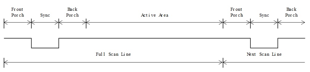
The Horizontal SYNC
| Scanline Part | Cycles | Duration (μs) |
|---|---|---|
| Active Area | 640 | 25.42 |
| Front Porch | 16 | 0.64 |
| Sync Part | 96 | 3.81 |
| Back Porch | 48 | 1.91 |
| Scanline | 800 | 31.78 |
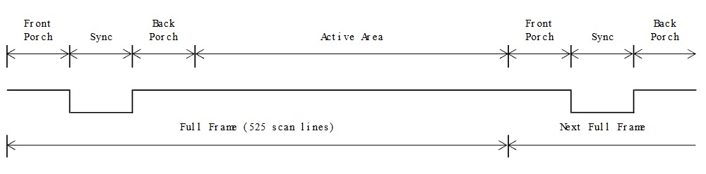
The Vertical SYNC
| Frame Part | Lines Count | Duration (ms) |
|---|---|---|
| Active Area | 480 | 15.25 |
| Front Porch | 10 | 0.32 |
| Sync Part | 2 | 0.06 |
| Back Porch | 33 | 1.05 |
| Full Frame | 525 | 16.68 |
Analog RGB signals
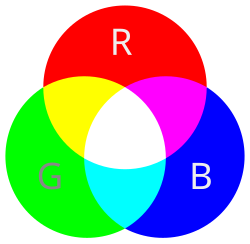
The transmission of color information is carried out through an analog RGB signal (Red, Green, Blue). The overall signal is separated into three independent channels, each carrying the information for one primary color:
- Red channel
- Green channel
- Blue channel
The signal level of each channel ranges from 0.00 V to 0.70 V, where:
| Level (Volt) | Brightness |
|---|---|
| 0.00 | Absence of Color (Black) |
| 0.35 | Medium Brightness Color |
| 0.70 | Maximum Brightness Color |
This range is generated by a digital-to-analog converter (DAC), which converts the digital value of each color into the corresponding analog voltage level. It is evident that three DACs are required, one for each color channel.
The combined activation of the RGB channels leads to additive color synthesis, which enables the creation of a wide overall color spectrum.
Hardware Architecture of the Serial VGA Controller
The VGA controller is implemented using a PIC 18F47K42 microcontroller, squeezing out every bit of its available horsepower through efficient utilization of its peripherals.
The choice of an 8-bit microcontroller was not accidental. While employing a 32-bit ARM Cortex-M device or an FPGA would have made the implementation considerably easier, it would undermine the very objective of the project. The aim was not to build a high-performance VGA controller, but to prove that even a resource-limited microcontroller, when paired with smart peripheral management and disciplined...
Read more »

 marble
 SingularitySurfer
 zpekic
 Pavel
Pavel
Very cool!