 mircemk
Very often, I receive a request from my viewers to explain the method of making the cases for my electronic projects. First of all, let me tell you that the cases are not made with 3D Printing, but from a special PVC material.
In fact, this is the secret to the beautiful appearance and versatility in the construction of these houses. I purchase this material from a local company for the production of illuminated advertisements and they simply call it PVC.
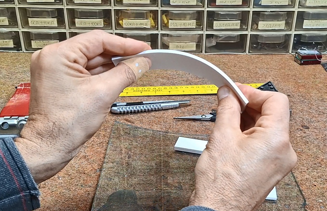
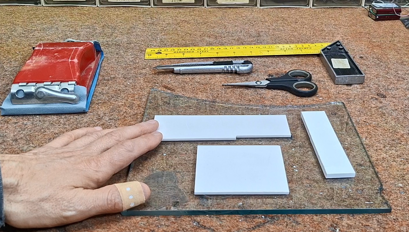
The material is relatively strong, but up to a thickness of 5mm it can be processed with a hobby knife. Even, they can be bent to a certain angle. The best surface for processing PVC is some hard material, and I specifically use a piece of 5mm thick glass. As for processing tools, we also need scissors, sandpaper and a metal ruler. Here's what cutting one piece looks like.
Now let's move on to the method of making a housing for a specific electronic assembly.
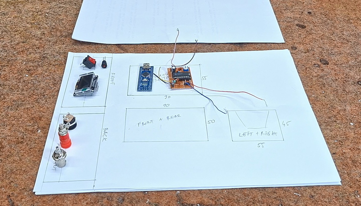
This time I will explain to you the making of the so-called "matchbox" housing, which is the most complex to make, but therefore the most practical. First, we need to determine the rough dimensions of the final box based on the components used in the assembly. In this case, I have a small PCB and an Arduino nano microcontroller, and on the front there will be an OLED display and a switch with an LED diode. On the back of the housing we need to have a power connector, an Antenna Input and a connector for connecting a regular wire. For easier access when installing the electronics, and possible service and adjustments (which is almost regular with DIY devices), we make the box with slightly larger dimensions than necessary. First we make a draft with dimensions on paper, and then we draw the pieces on the PVC material.
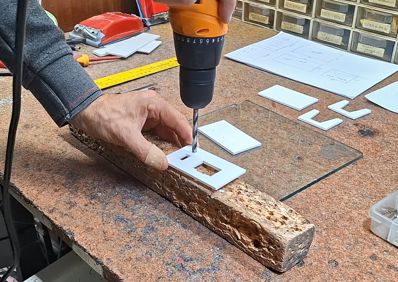
The inner part of the box is made of 3mm PVC. After we draw the parts, we move on to cutting them. Then we make appropriate openings on the front and back. The straight lines are cut with a hobby knife, and the round ones with a drill and similar woodworking tools.
When we are done cutting, we slightly sand the edges and move on to gluing. For this operation, we can use one of the many universal glues, but it is not recommended to use super glue at this stage. This is what the finished inner part of the box looks like, in which the electronic assembly will be installed.
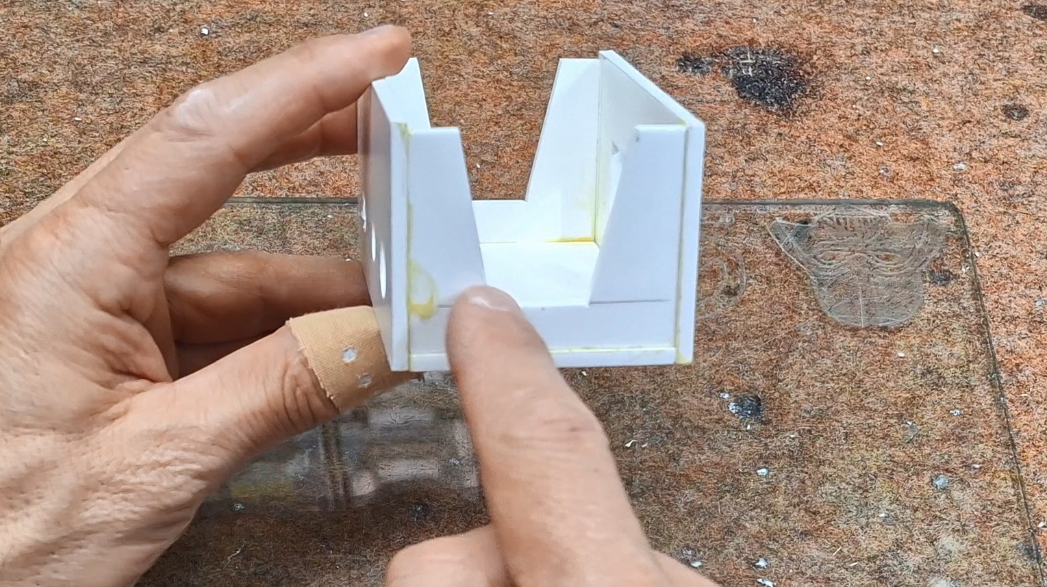
As you can see, both sides are "open" in order to have better access to the components inside. For larger boxes, it is practical to make the back box modular, i.e. to attach it to the rest of the box with screws. After this comes the construction of the armor around the box. Now a very important note: the internal dimensions of this "shell" should be one millimeter larger than the length and width of the inner box, so that it can move freely back and forth, just like a matchbox.
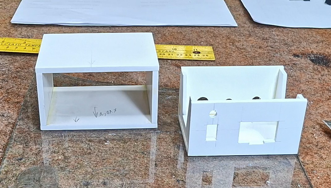
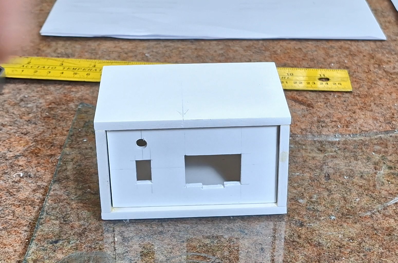
For a better visual impression, this part is made of thicker PVC board, specifically 5mm. We also sand this part and glue it with universal glue. Here's what the finished box should look like. The inner part should move freely within the armor.
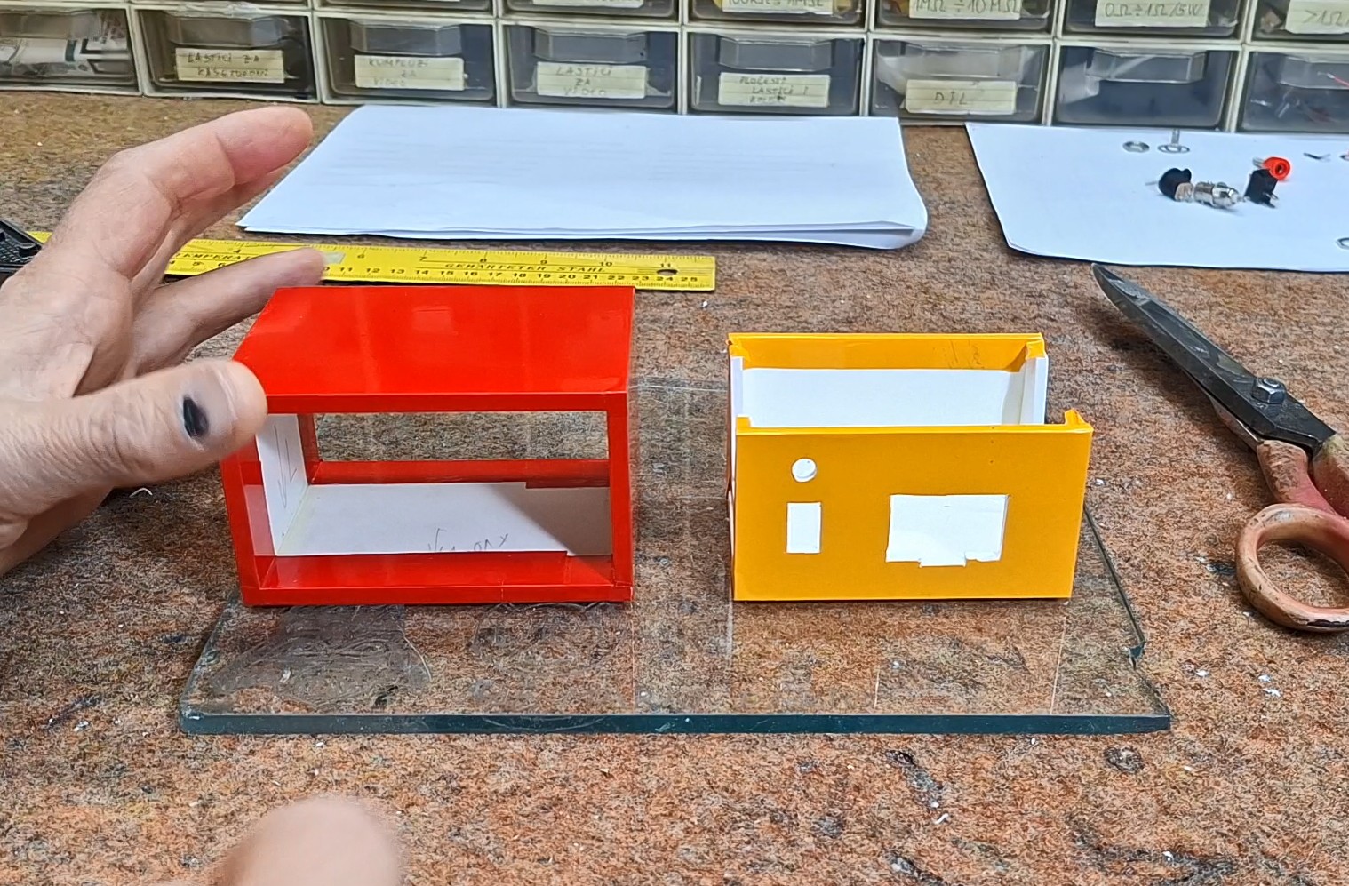
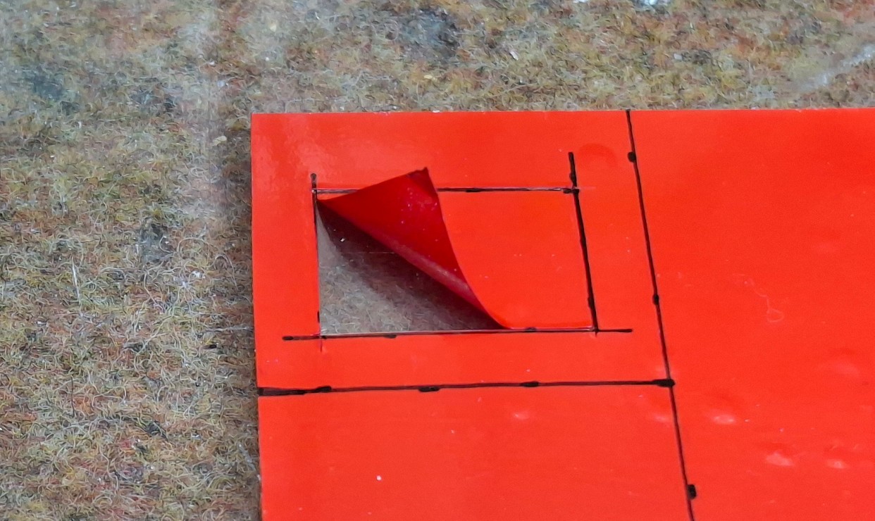
Next comes the covering of the box with self-adhesive wallpaper. Most often, the front and back of the box are covered with a lighter color (white or cream) because then the markings that will be printed need to be legible. We choose the color of the armor according to our wishes. Let me just tell you that sticking wallpaper requires a little more patience and experience that you will gain over time.
Now it's time to mount the electronic part inside the box. First, the elements on the front and back are mounted (in this case the switch with the LED, the Display, and the connectors on the back). Specifically, I will attach this small display on the back with double-sided adhesive, and on the front I will put a special mask, the making of which you will see below.
Now we attach the PCB in some way (the easiest way is with double-sided adhesive) to the bottom and make...
Read more »
 Makerinator
 matthewkleinmann
 Daniel Domínguez