 Prashant Sinha
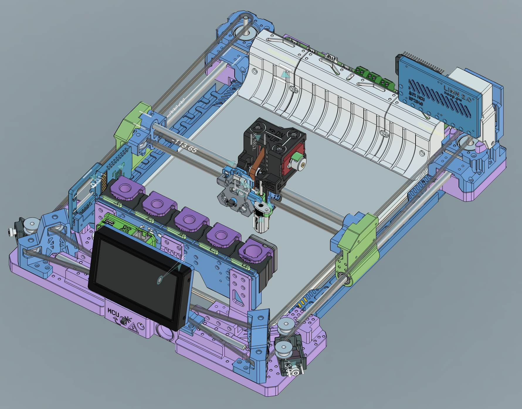
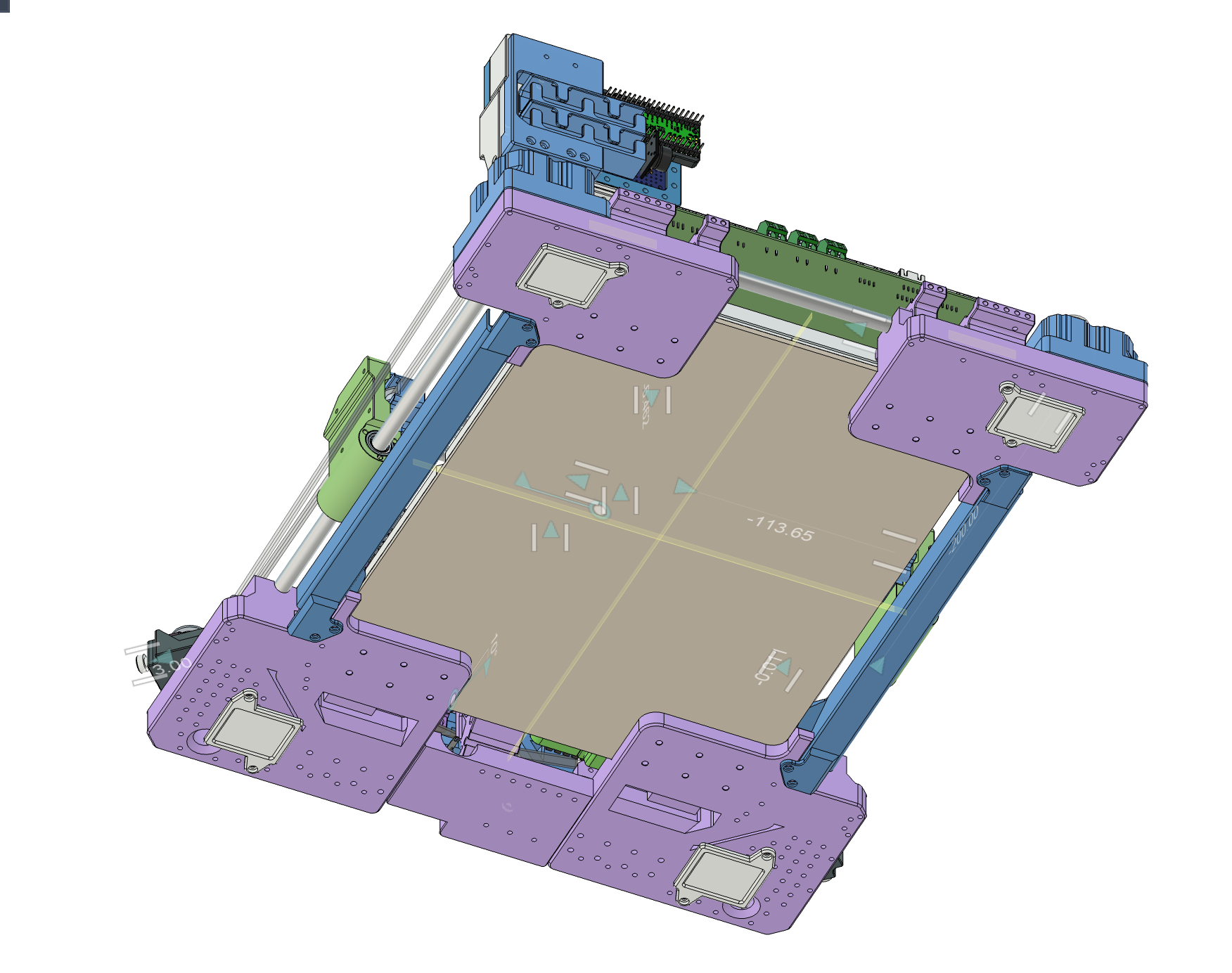
The plotter is designed to be scalable. Four components in each corners mate with variable lengths of rods/belts/base.
A hard MDF board and the four steel rods on the edges together form a sufficiently rigid and square frame. I got the rods and bearings from a Tronxy 3D Printer Kit, as well as the driver PCB and XY Stepper Motors.
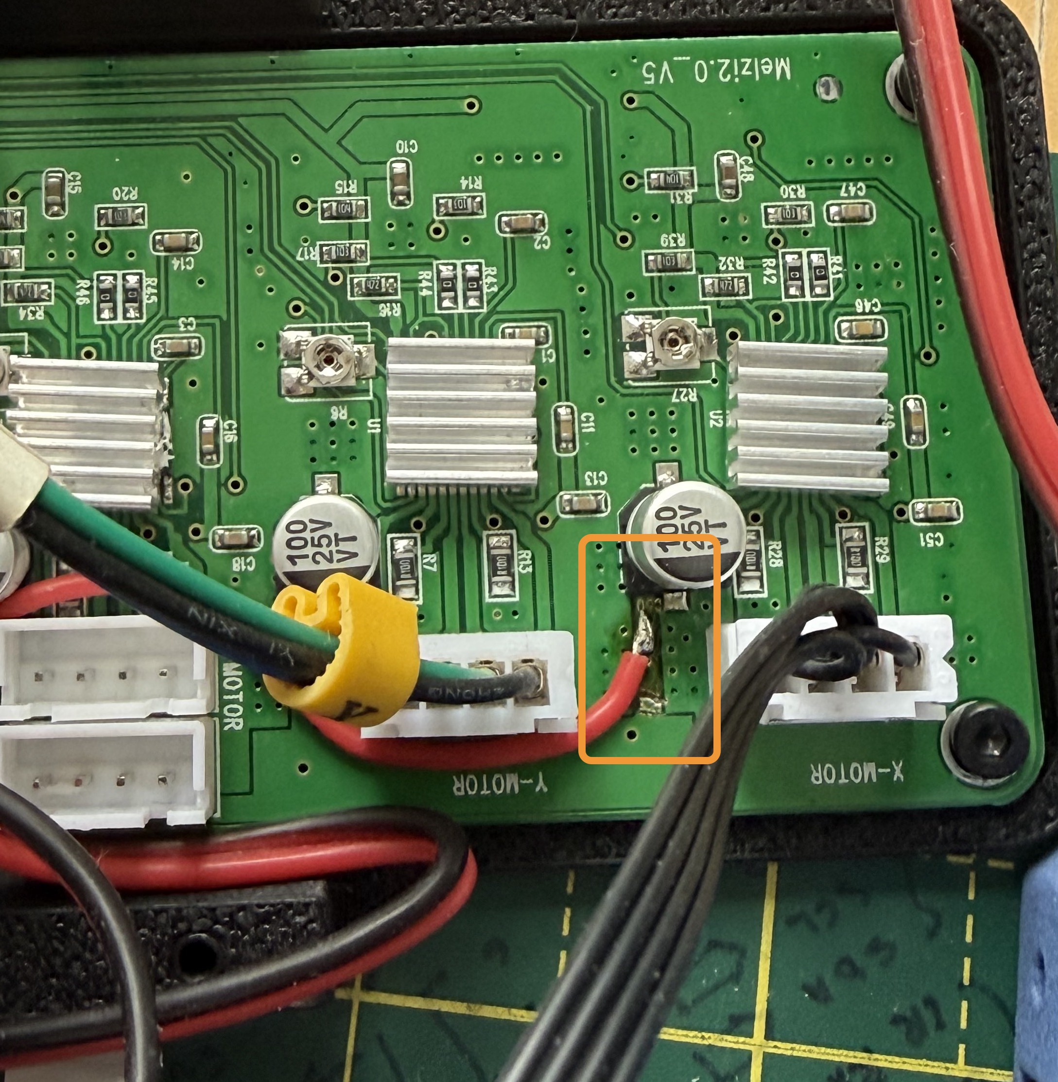
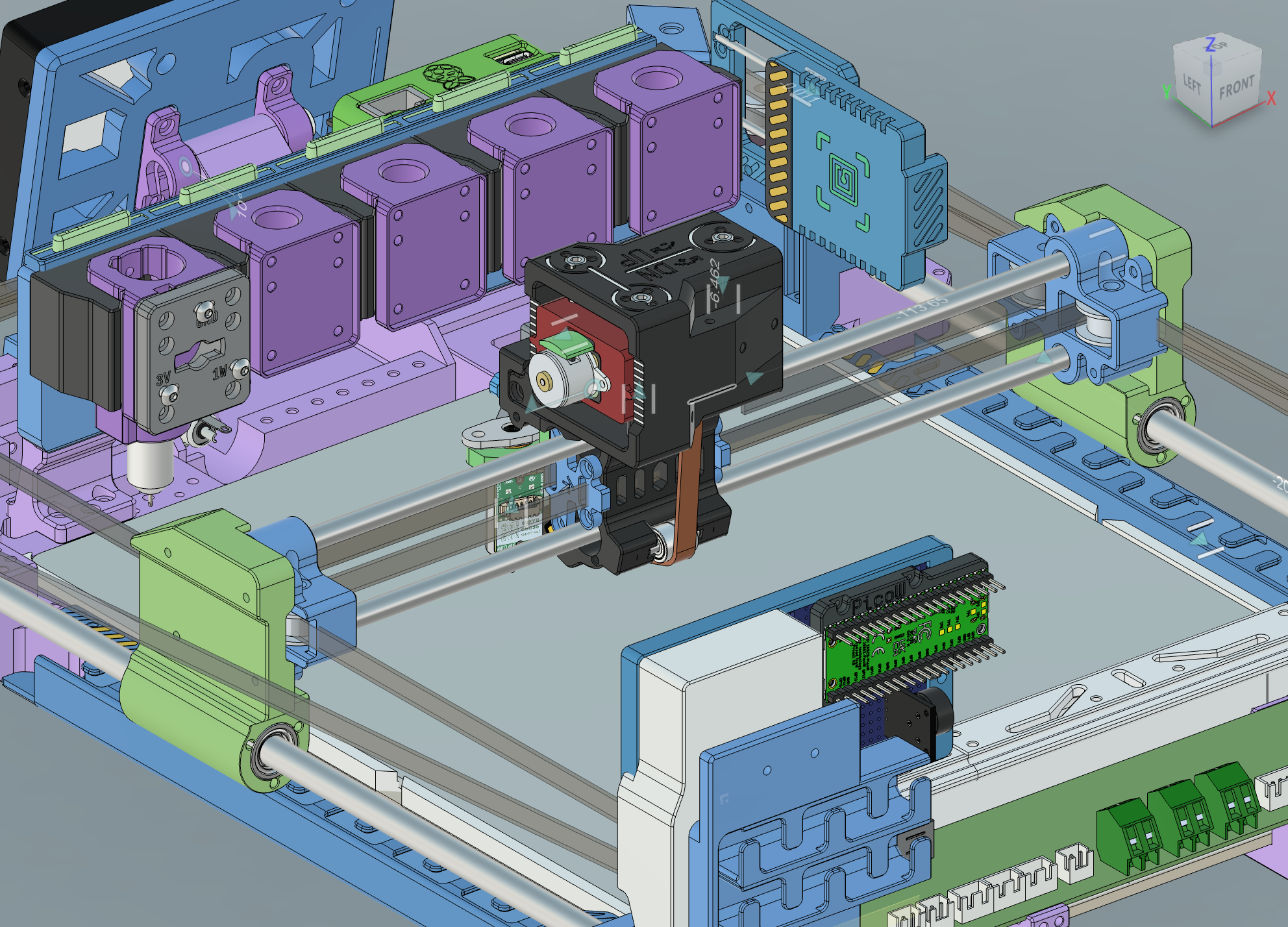
The driver board uses 12V, and has 4 A4982 driver chips. Z axis is configured to drive dual Z axis motors so we have a different pinout here for the motors.
I'd noticed the small SRM1509 and Linear motors get too hot on 12V regardless of proper VREF, so I cut the 12V trace and supplied external 5V to Z and K (the toolhead lock) axis drivers.
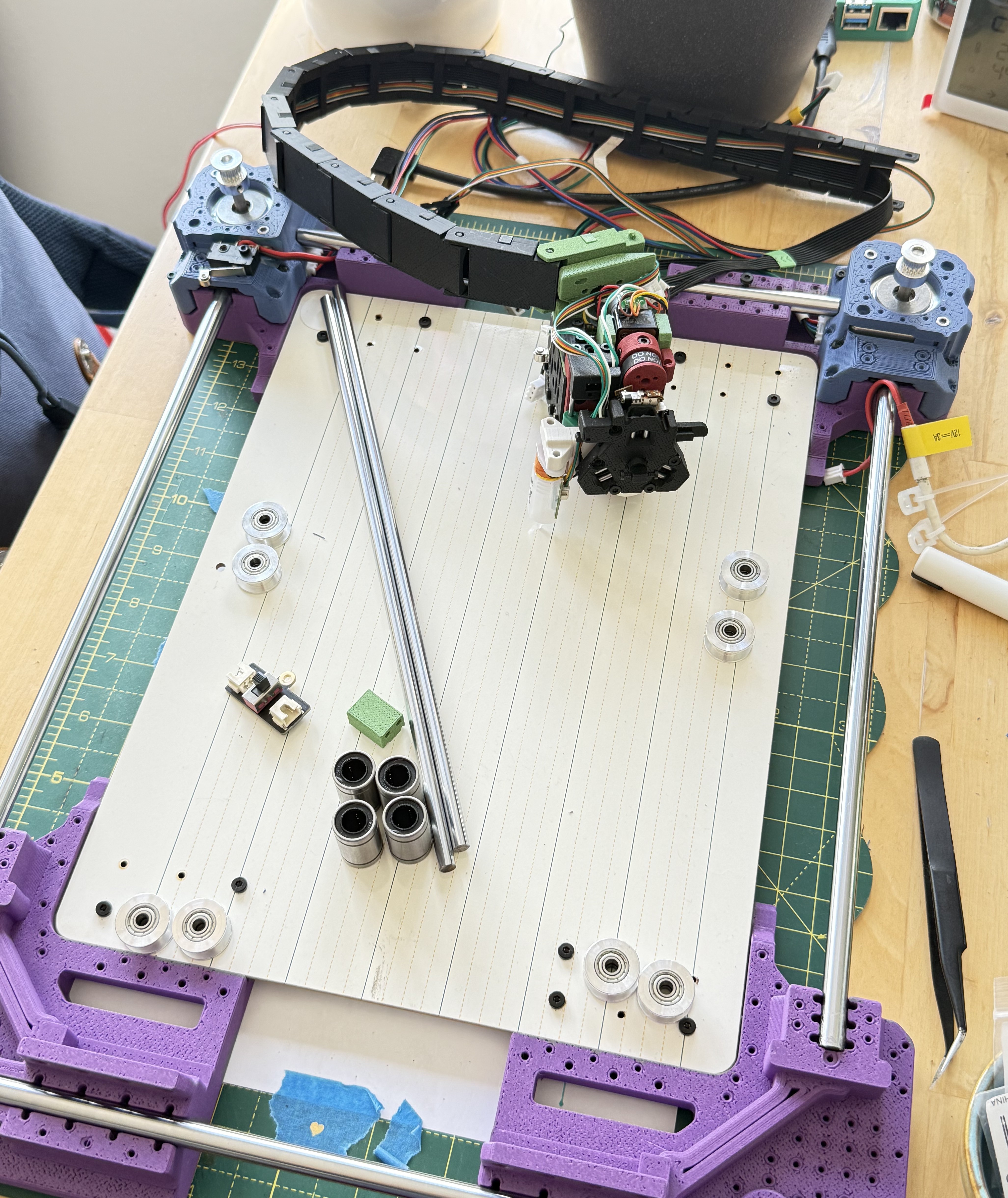
When the belts are tensioned the frame is pulled inwards along the belt direction, which reduces the wobble. However it will likely deform when lifted in the current setup. There is not much to do unless we switch to a metal frame.
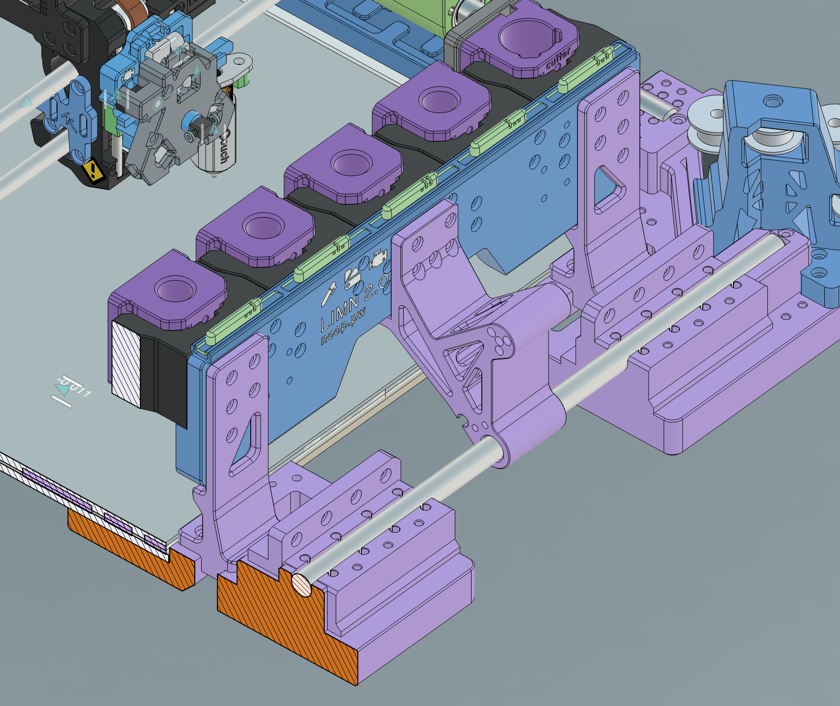
The tool dock however needed special consideration as we need it to not move and survive the toolhead crashing into it. To keep it positioned the brackets (shown below) mate with a steel rod, and rest on the base. The middle one also acts as a hinge for the LCD.
--
I'm quite close to finishing the design. I've built a 1:1 model in Fusion360, and would just like to give a shout to amazing people on GrabCAD and Printables (and elsewhere) for sharing their models. I'll be posting the STEP files on Printables (about a week or so). There are many parts, with some parts such as the K axis requiring special considerations (and it's pretty specific to the hardware I had at hand) so there's a bit of work left to do to documenting them. Almost all parts print without supports.
Discussions
Become a Hackaday.io Member
Create an account to leave a comment. Already have an account? Log In.