 JP Gleyzes
As an RC planes enthusiast, I already designed several planes using foam cutting technics.
To do this you will need a foam cutter machine and a "board" to pilot it. Regarding the board, I already published a cheap FluidNC 4 axis controller.
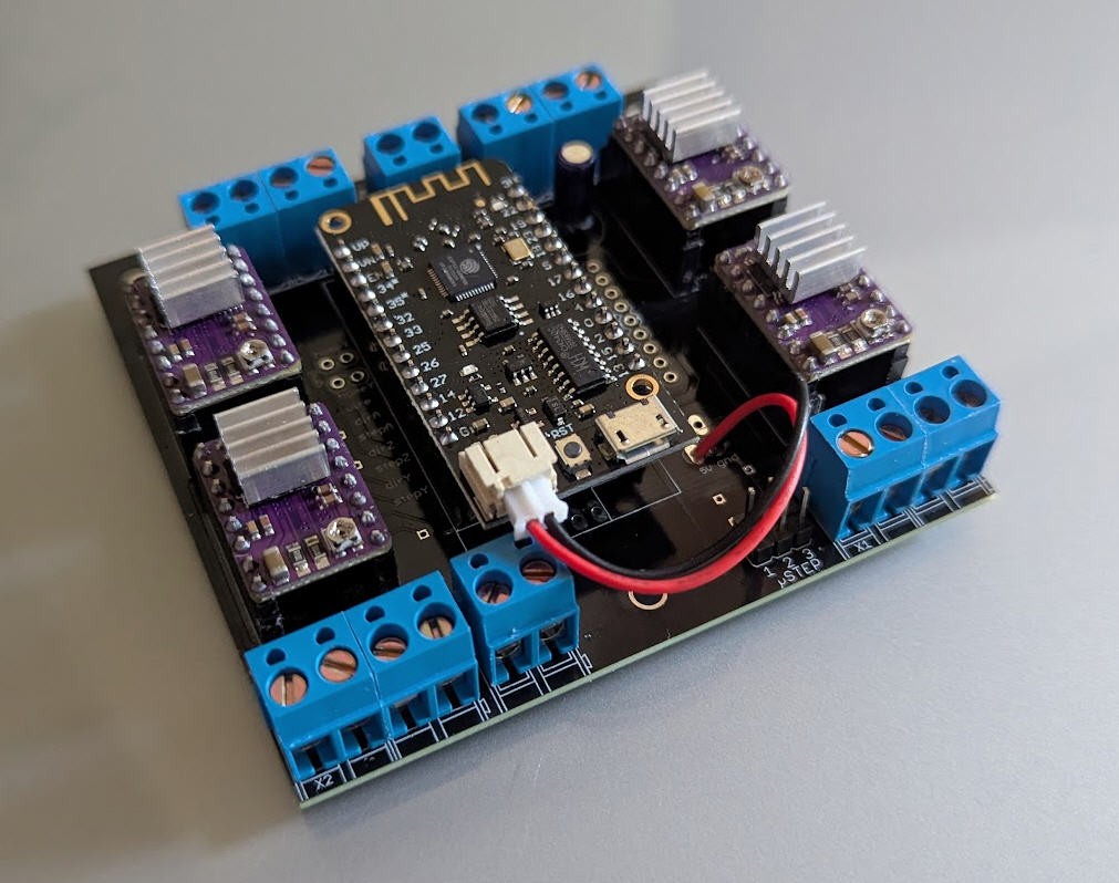
This controller has already proven to work very well. But it needs "software" to produce the Gcode and to control the board. This is exactly what this project is dealing with !
Although several solutions does already exist, none of them were (IMHO) simple and powerful enough for my needs...
So I wrote two applications :
- WiHoWI (Wing hot Wire) devoted to design the Gcode file of the wings
- hoWiGs (hot Wire Gcode Sender) devoted to drive the FluidNC controller
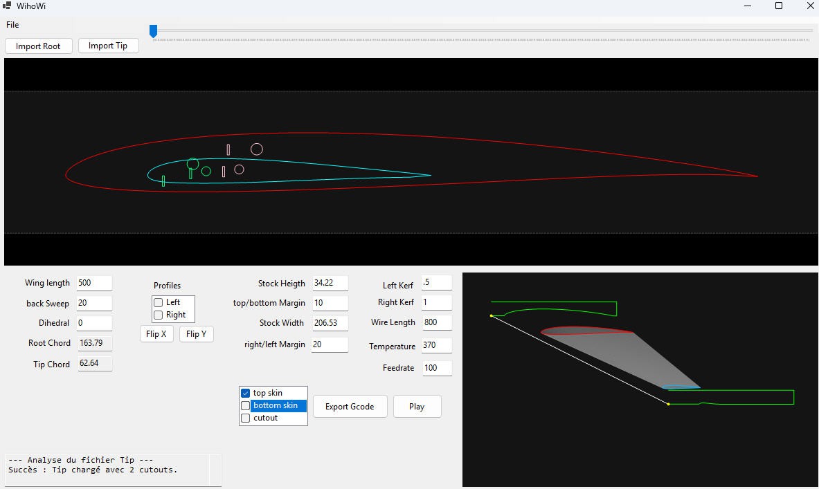
WiHoWI : CNC 4-Axis Hot Wire Wing Cutter
WiHoWI is a specialized CAD/CAM utility designed for 4-axis CNC foam cutting.
This software synchronizes two independent 2D profiles (Root and Tip) to generate precise G-Code for tapered wings, including complex internal cutouts and automatic stock material management.
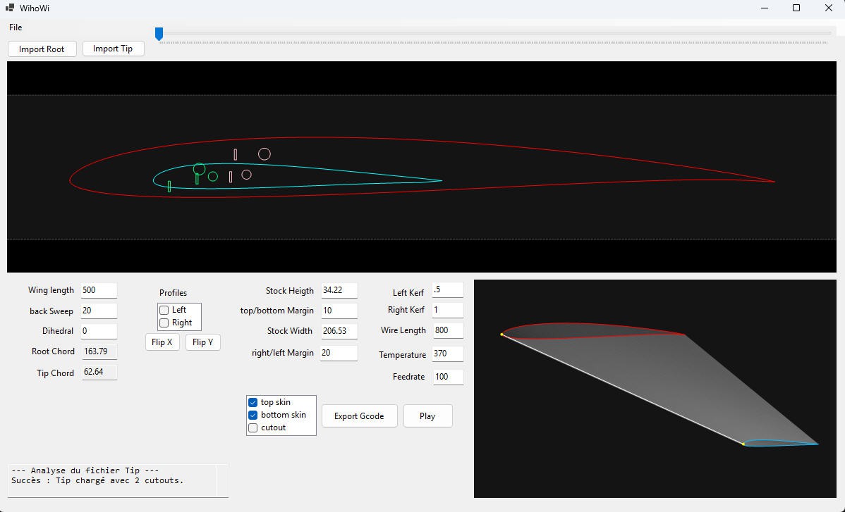
Key Features and usage
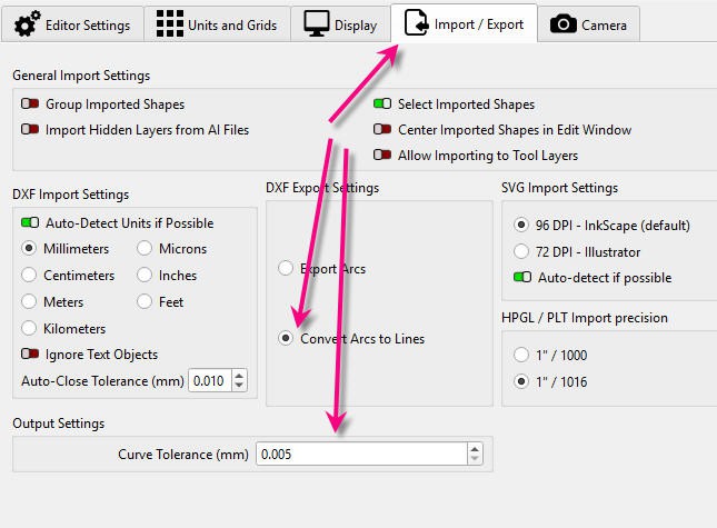
Dual Profile Synchronization: Import Profiles: Use the `File > Open` menu to open existing projects (.whw) or use dedicated buttons to load DXF files for the Root and Tip.
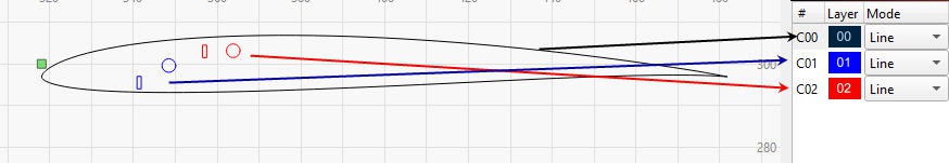
You can use any CAD software able to produce "polylines" dxf. (above lightburn example)
It works also with the free version of QCAD :
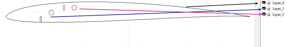
remember :
- layer 0 : contains the profile
- layer 1 : contains the cut outs attached to the intados
- layer 2 : contains the cut outs attached to the extrados
Remember also to choose the "polylines" option for lightburn... currently the software does not support Splines...
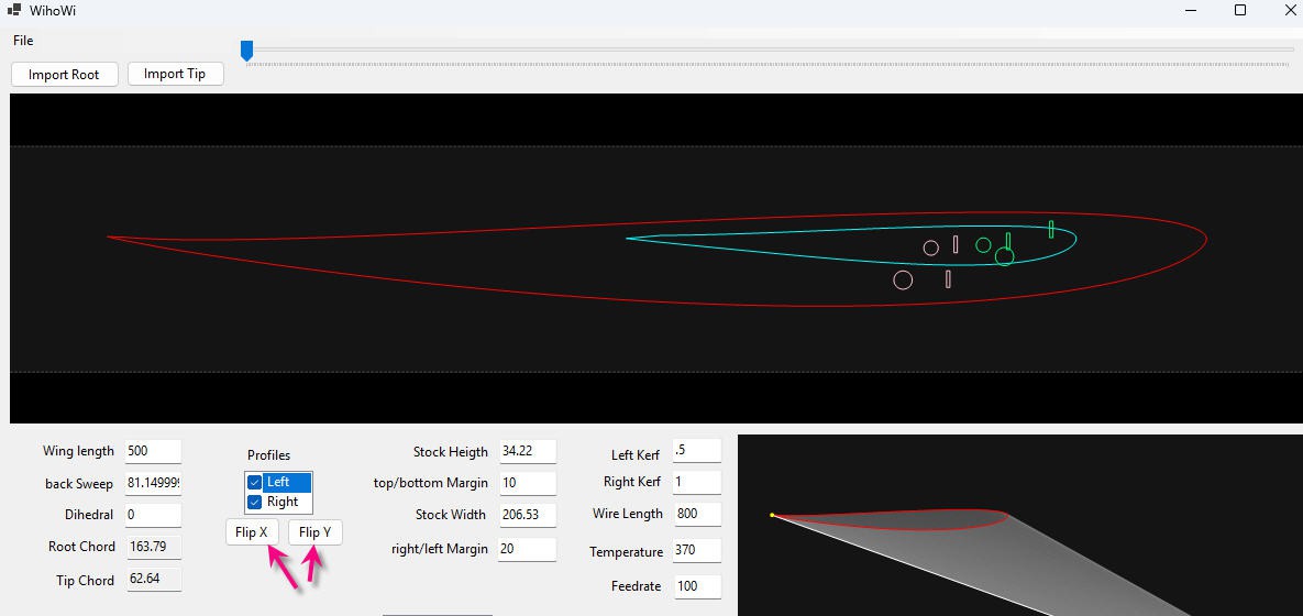
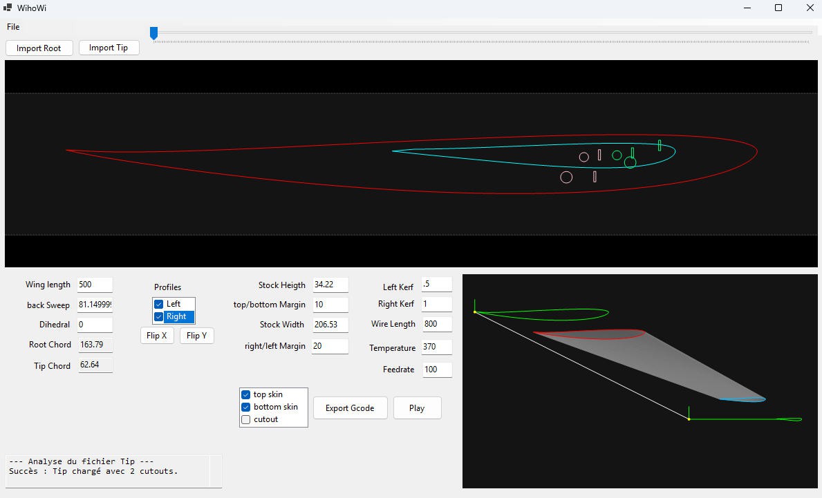
Define Geometry:
- Enter the Wing Length.
- Adjust Back Sweep and Dihedral
- Note: Root/Tip chords and washout angles are automatically computed from the DXF and cannot be changed manually. Software automatically identifies the Leading Edge (LE) to serve as the pivot point (0,0) for sweep and dihedral calculations.
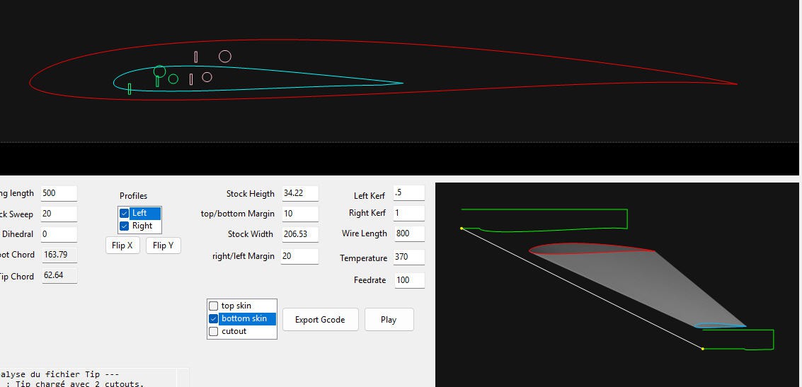
Dynamic Stock Visualization: Automatically calculates required block dimensions based on dihedral, sweep, and safety margins.
Flipping: Integrated X and Y mirroring to adapt profiles for left/right wing panels without re-designing the CAD file. (tick the profile(s) you want to flip and apply)
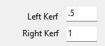
Advanced Kerf Compensation: Supports asymmetric kerf values for the left and right towers to account for heat dissipation differences.
4-Axis G-Code Generation:
Produces synchronized X/Y and A/Z movements with controlled transition speeds (G1) to maintain wire tension and accuracy.
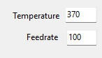
you can choose:
- Feedrate: Default cutting speed (expressed in mm/min)
- Temperature: PWM control (0 to 1000) to match material density.
Synchronization: Ensures that both the Root (X/Y) and Tip (A/Z) towers reach their respective destinations at the exact same moment. This critical for tapered wings where the path lengths differ between the two towers.
Remember that CNC Origin is located on the left edge at the bottom of the foam stock.
When ready you have several options to produce the paths
Top Only: will cut only the top skin (from left to right and exit on right stock side)
Bottom Only : will cut only the bottom skin (from left to right and exit on right stock side)
Top + Bottom : will enter left of stock, then cut top skin then cut the bottom skin (from left to right then right to left and exit on left stock side) (note that I also flipped the profiles to enter cut by the trailing edge
CutOuts
They can be cut in a single path with the core of the wing or in multi paths.
When cut in a single path, the software will garanty that the wire enters and exists at a synchronized point into the foam. Note that intrados and extrados cut outs are attached as expected/described into the dxf.
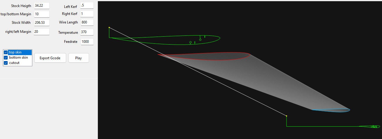
On the following picture, I pressed...
Read more »