mircemk
A Variable Frequency Oscillator (VFO) is an electronic circuit that generates a signal at a tunable, adjustable frequency, essential for controlling the operating frequency in radio transmitters and receivers. So far, in several of my previous videos, I have shown you how to make such a devices using the Si5351 clock generator. This time I will explain how to make a VFO but now with the AD9850 Signal Generator Module.
The AD9850 chip generates a pure sine signal in the range from 0 to 40 MHz. The Si5351 is indeed more advanced and cheaper, but at the output it generates a rectangular signal rich in harmonics, which in the receiver generate non-existent Image signals, which means we listen to the same radio station on multiple receiving frequencies.
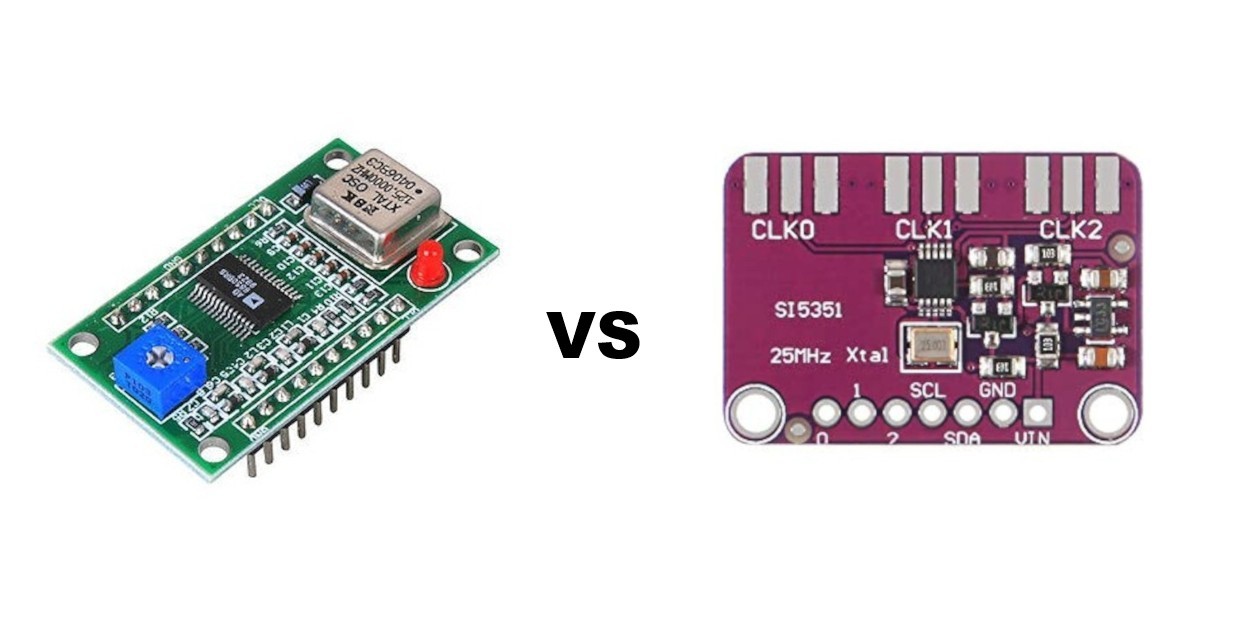
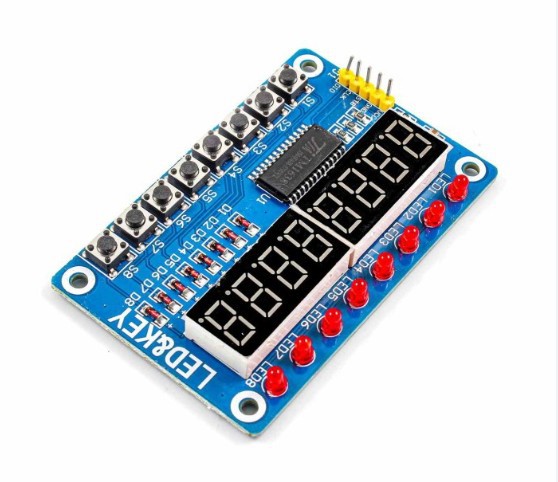
In that sense, the AD9850 is superior because it generates a pure sine signal that has a much smaller number of harmonics and is very suitable for use in local oscillators of HF radio devices. This time, to display the generated frequency, I will use the ultra-cheap TM1638 module, which is ideal for this purpose, combining an 8-digit 7-segment display, 8 LEDs, and 8 buttons, all controlled via only 3 digital pins.
This project is sponsored by PCBWay. From concept to production, PCBWay provide cutting-edge electronic design solutions for global innovators, Including hardware design, software development, mechanical design, product testing and certification. PCBWayengineering team consists of experienced engineers in electronics, embedded systems, and product development. They successfully delivered hundreds of projects across industries such as medical devices, industrial automation, consumer electronics, smart home, and IoT.

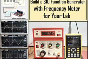
The 7-segment LED numbers give the entire device a nice retro feel. The module is also compact and well-made, so it can be used directly on the front of the box, greatly simplifying the construction of the device.
Now let's take a look inside and see what components this device contains.
- fst, there's the AD98500 module,
- Arduino Nano microcontroller board,
- a rotary encoder,
- and the previously mentioned TM1638 module.
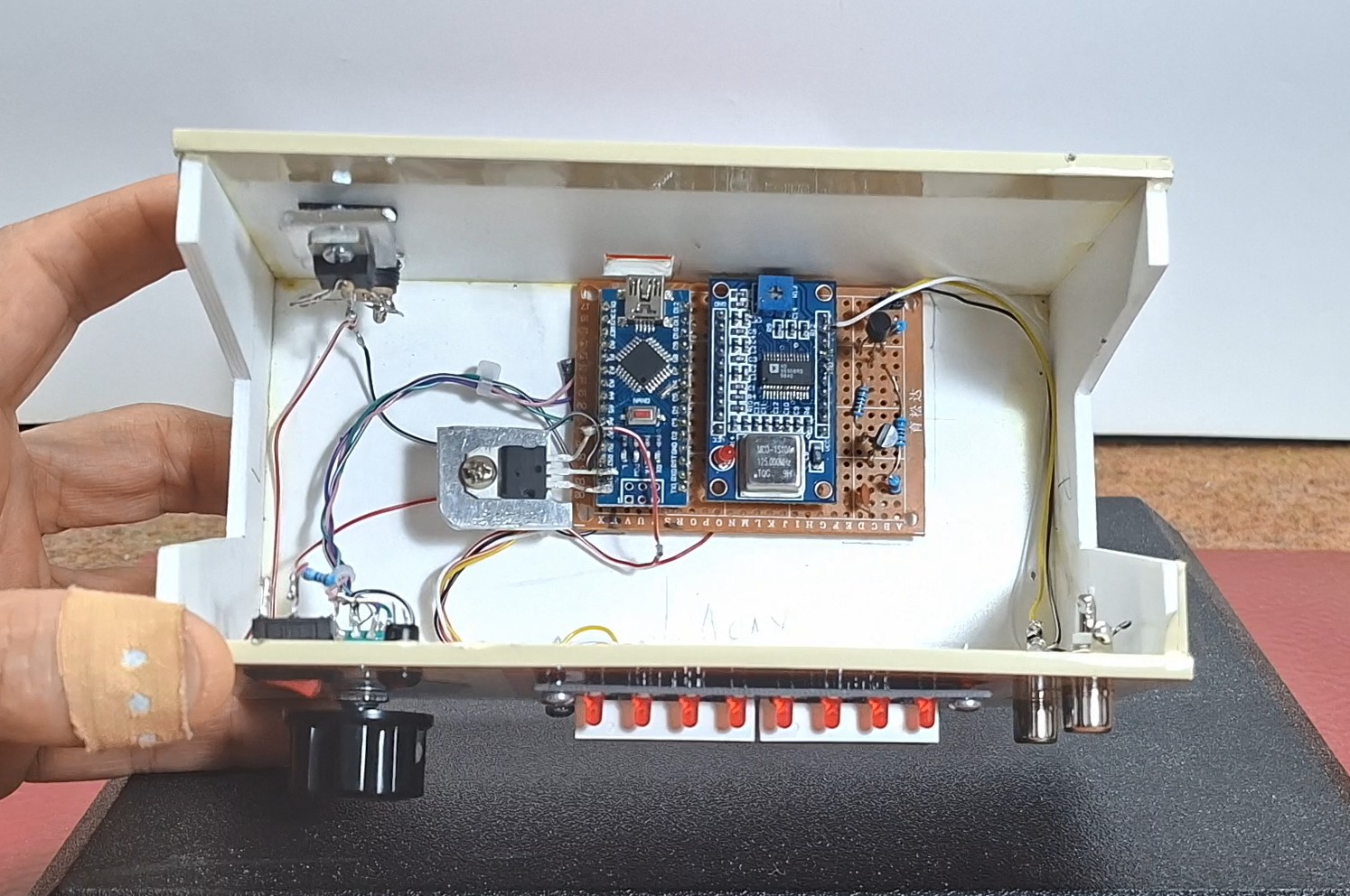
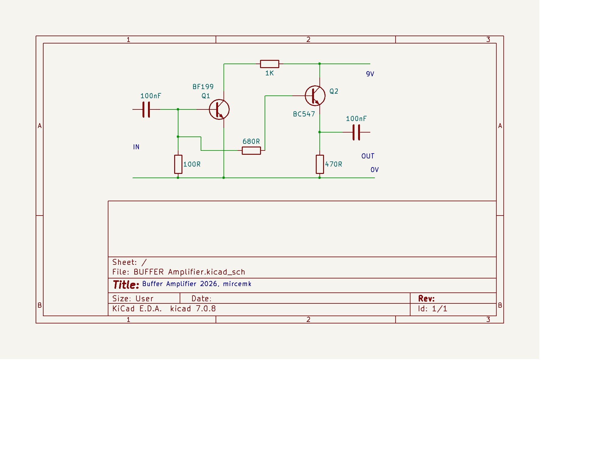
You can see two more components mounted on heat sinks and an additional assembly with two transistors on the PCB. The assembly is a Buffer Amplifier that raises the signal level from 1 to 5Vpp, this one is an LM317 stabilizer and provides 9V for the buffer circuit and the other one is a 7805 linear stabilizer through which the AD98500 module is powered. I made these additional modifications for the needs of one of my devices with special requirements, otherwise the assembly without these modifications is quite sufficient, using a direct 5V power supply. You can also see the schematic of the buffer amplifier below.
Now let's see how the device works in real conditions. Immediately after turning on the display shows the default frequency that was previously entered in the code. With the rotary encoder we can change this frequency in steps of 1kHz. On the first button we can change this step to 10Hz 100Hz 1kHz, 10kHz and 100kHz. On the second button the modulation type AM, USB, or LSB is changed. The next 5 buttons are used to directly activate one of the 5 most used HF Bands successively. (1.8, 3.5, 7, ....). It is important to note that we can continuously change the frequency from one band to another, so this also includes broadcast frequencies. The last button has a function when using this VFO with Superheterodyne receivers with an IF of 455KHz. Namely, by activating this option, the actual output signal is 455KHz higher than the one shown on the display. The eight LEDs at the top, signal which of the options is currently active. Another very useful feature is the ability to change the intensity of the display and LED lighting. By pressing the encoder button we enter a mode where the display brightness can be changed from 0 to...
Read more »
 sq7bti