 nobcha
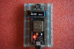
The tinySA now has an SG function. I needed a SINAD meter for receiver sensitivity tests. So I built one on an ESP32-C3 and also on a Raspberry Pi Pico.
What it does
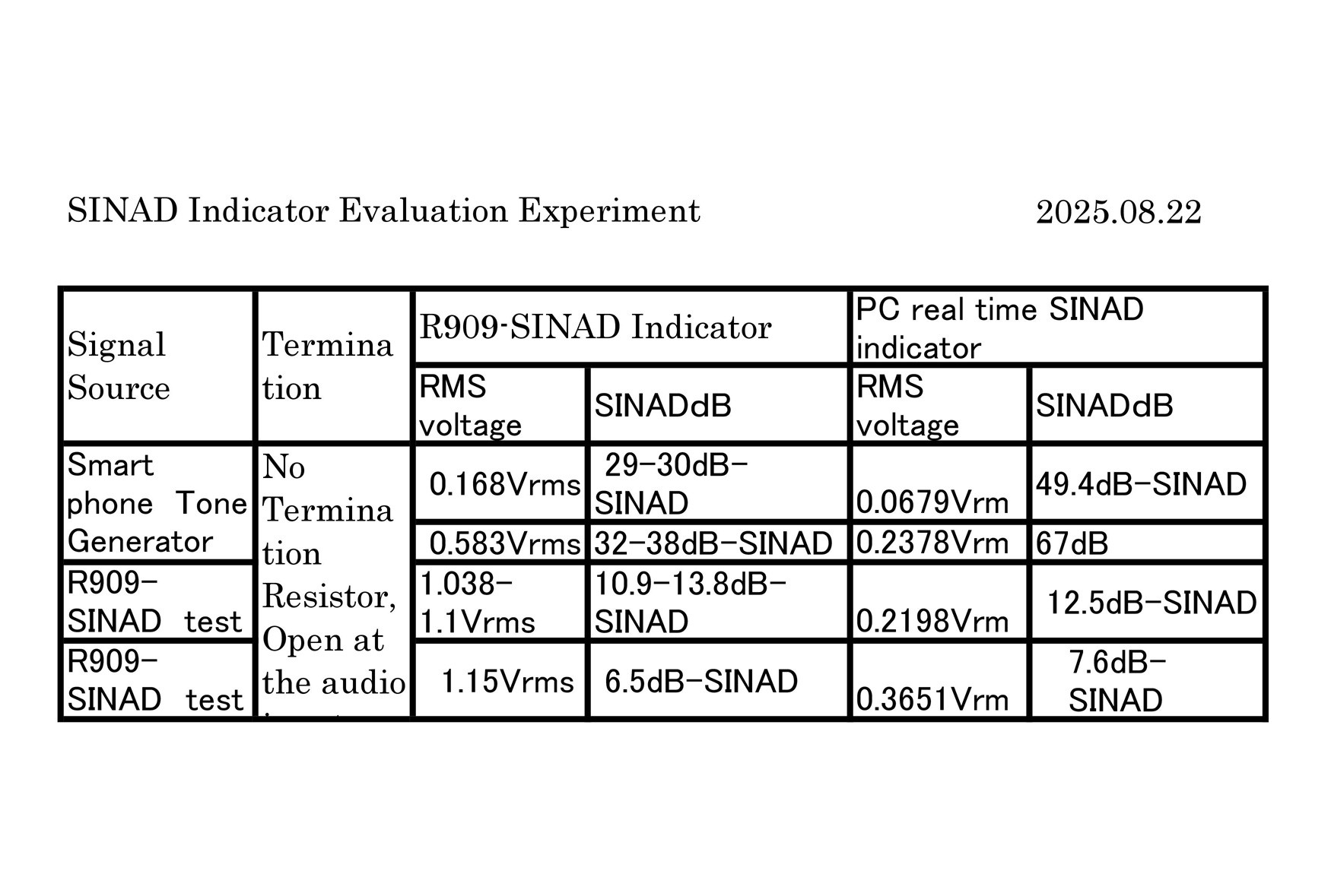
- SINAD measurement: 10kHz sampling, 1kHz digital notch filter (IIR)
- Waveform display: Real-time audio waveform
- FFT spectrum: Visualize noise and distortion
Why SINAD?
(Signal + Noise + Distortion) / (Noise + Distortion). Includes distortion. Tells you about usable signal quality. Works for FM, AM, and SSB.
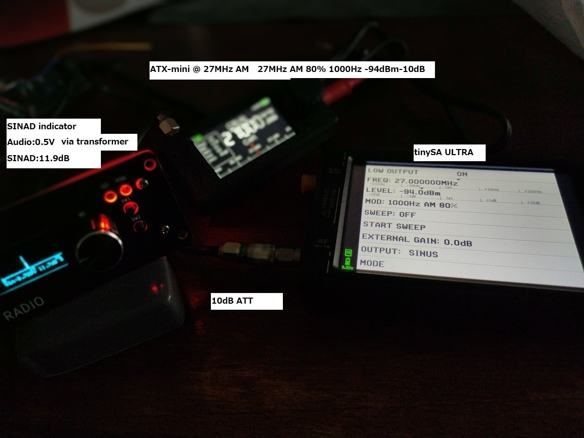
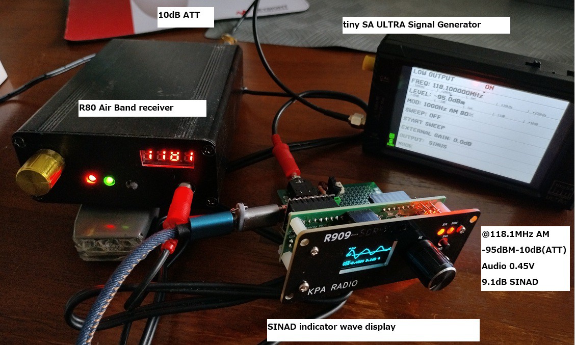
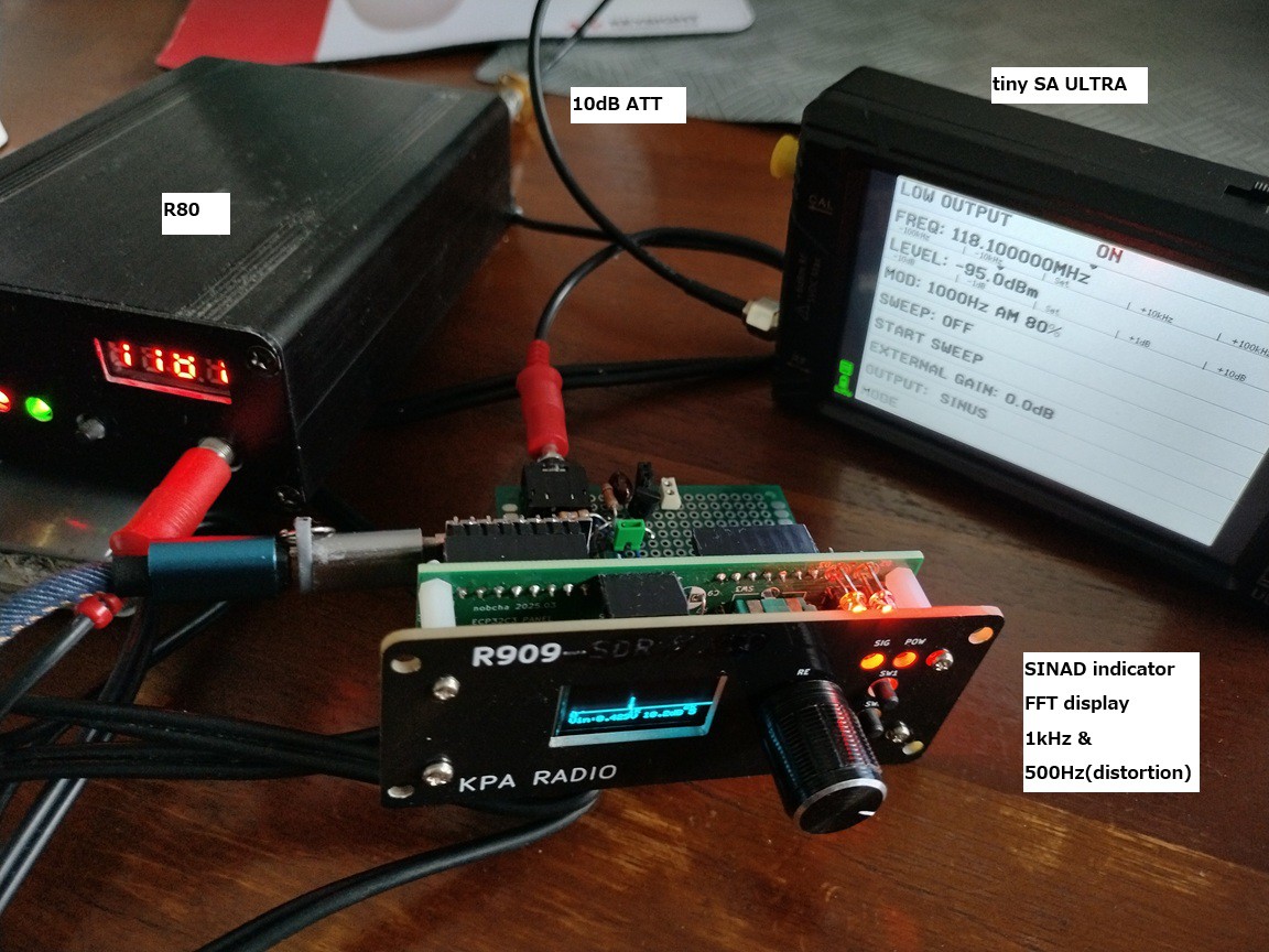
The setup
tinySA ULTRA(SG) → Receiver under test → ESP32 SINAD meter or RPP SINAD meter
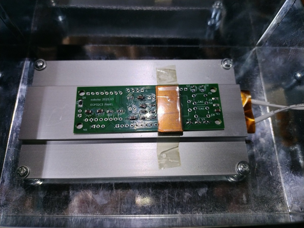
Code & hardware
Open source. { https://github.com/Nobcha/R909-SINAD/blob/main/}
This short video shows the ESP32-based SINAD meter in operation, including real-time SINAD readout and FFT display.
👉 https://www.youtube.com/watch?v=a2N7Uo3oPMg
In the video, notice how the SINAD value changes with signal level and how the FFT reveals noise and distortion components.
Referrence:
BLOG:https://hrd-737.hateblo.jp/entry/2025/07/05/165913
*This is a hobby project. Works for me. Maybe it works for you too.*

 Igor Brkic
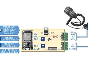
 Ryan Kinnett
 aeropic