 nobcha
Background and Motivation
It started with a small surprise.
My nanoVNA has a built-in signal generator function. One day I realized: if I have a calibrated RF source right there on my bench, why not use it to measure receiver sensitivity properly? That question set everything in motion.
Receiver sensitivity measurement has a surprisingly fragmented history. In the professional world, digital modulation has taken over, and BER (Bit Error Rate) has become the natural sensitivity metric. But analog modes never disappeared — they just stopped evolving.
For FM receivers, SINAD (Signal to Noise And Distortion) is the established standard. But AM and SSB receivers — both in amateur and professional use — still rely on NQ (Noise Quieting) as a proxy. NQ is intuitive, but it is loosely defined and difficult to compare across different receivers and operators.
There is a growing argument that SINAD should become the universal sensitivity standard across all modulation modes — FM, AM, and SSB alike. I find that argument compelling. SINAD is more rigorous, more reproducible, and once you have the right tool, easier to apply than most people assume.
The problem is that SINAD meters have traditionally been expensive, specialized instruments. That felt like an unnecessary barrier.
So I decided to build one.
Principle of SINAD Measurement
The analog origin
The original SINAD meter was a purely analog instrument. Its core was a 1kHz notch filter — a narrow band-reject filter tuned precisely to remove the test tone from the receiver's audio output.
The measurement procedure was simple:
Feed the receiver a 1kHz modulated RF signal from a signal generator
Measure the total audio output level (S+N+D) — signal, noise, and distortion together
Switch in the notch filter to remove the 1kHz tone
Measure the remaining output (N+D) — noise and distortion only
Calculate the ratio:
SINAD (dB) = 20 × log10 ( (S+N+D) / (N+D) )
The digital implementation: IIR notch filter
In this project, the analog notch filter is replaced by a digital IIR (Infinite Impulse Response) notch filter — the direct digital equivalent of the analog circuit.
The IIR notch filter is tuned to 1kHz in software, and applied to the sampled audio stream in real time. This eliminates the need for precision analog components, and the filter characteristics can be adjusted freely in code.
Analog approach: hardware notch filter → level meter
Digital approach: ADC sampling → IIR notch filter → power calculation → SINAD
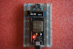
This is the core of the measurement engine — implemented first on ESP32-C3.
FFT as a diagnostic tool
The implementation also includes FFT (Fast Fourier Transform) analysis, but this serves a different purpose — it is not used for the SINAD calculation itself. Rather, FFT provides a visual spectrum display, useful for:
Verifying that the 1kHz test tone is present and clean
Checking for interference or spurious signals in the audio
Diagnosing the receiver's noise floor visually
In short: IIR notch filter for measurement, FFT for diagnosis.
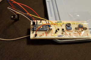
The necessary functions described above will be implemented using a prototype circuit with an ESP32-C3 in the Arduino IDE.
Demo Video (Real-time SINAD measurement)
This short video shows the ESP32-based SINAD meter in operation, including real-time SINAD readout and FFT display.
👉 https://www.youtube.com/watch?v=a2N7Uo3oPMg
In the video, notice how the SINAD value changes with signal level and how the FFT reveals noise and distortion components.
Referrence:
Schematics:https://github.com/Nobcha/R909-SINAD/blob/main/R909-VFO_ESP32_SCM.pdf
BOM:https://github.com/Nobcha/R909-SINAD/blob/main/5531_esp_25_BOM.pdf
Gerber files:https://github.com/Nobcha/R909-SINAD/blob/main/5531_esp_25.kicad_pcb.zip
Sketch:https://github.com/Nobcha/R909-SINAD/blob/main/try_7_3i_sinad_meter.ino
Referring sketch:https://github.com/Nobcha/R909-SINAD/blob/main/filter%20section.ino
 SingularitySurfer
 Darren Winter