 Arnov Sharma
-
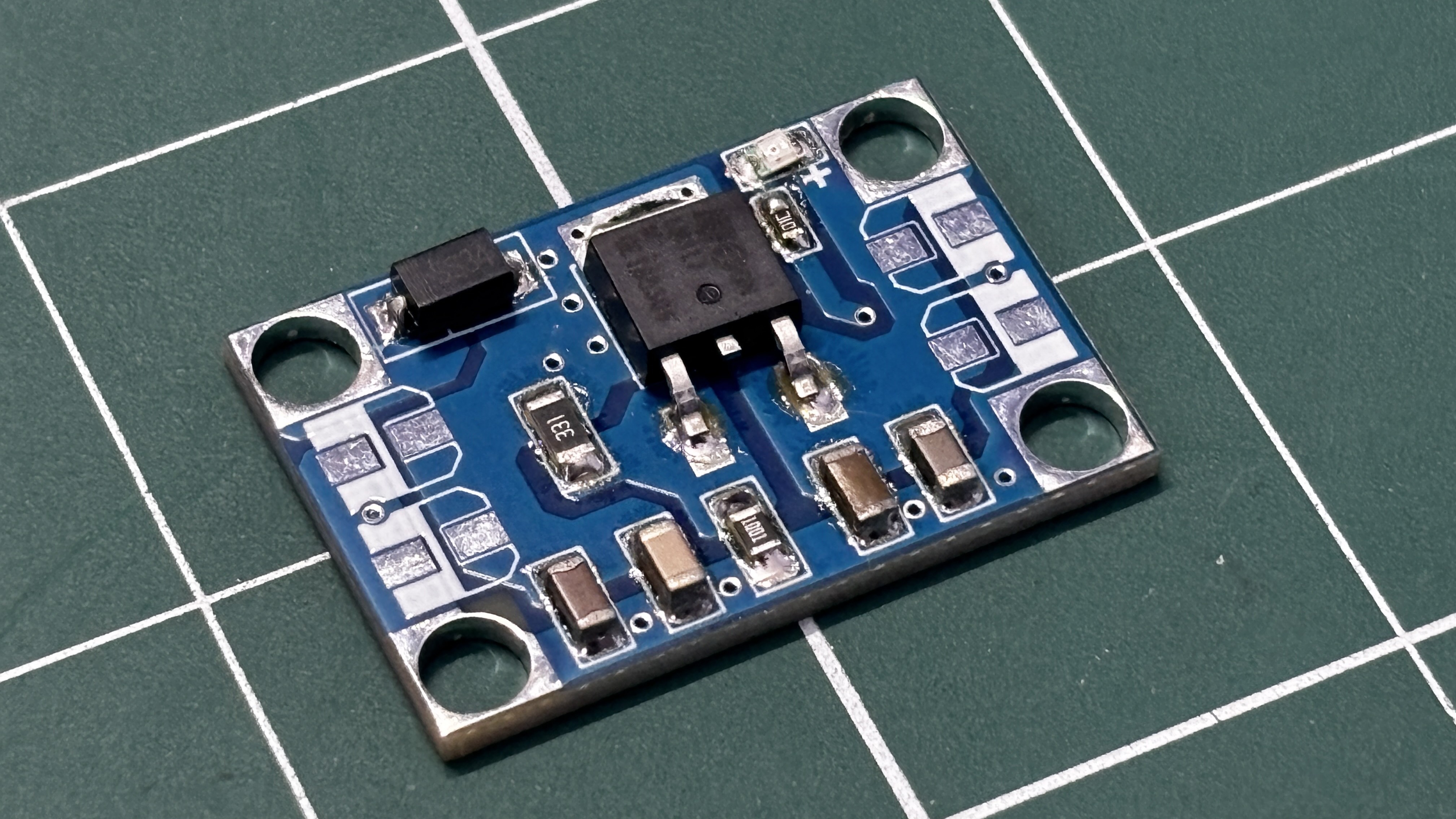
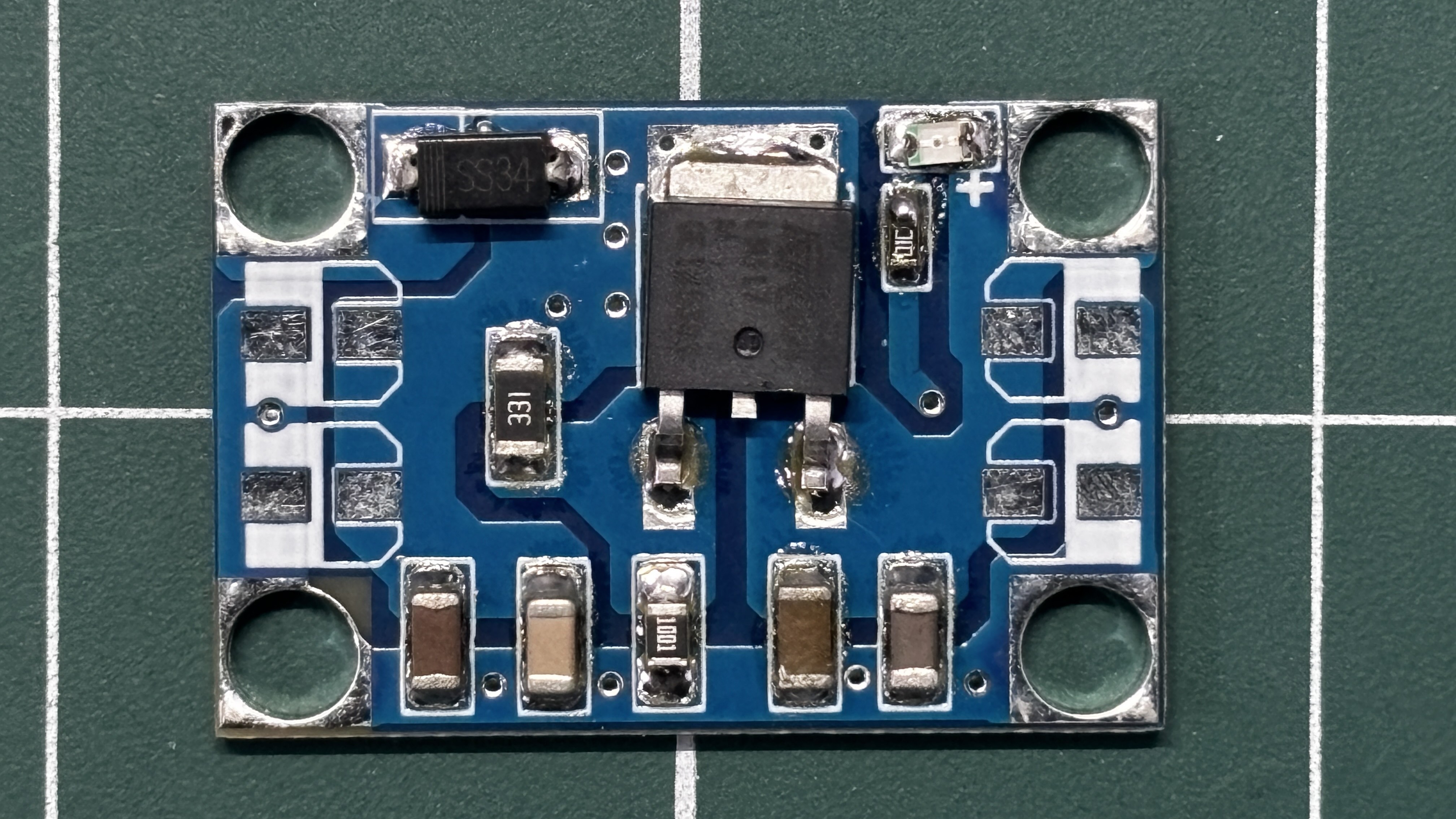
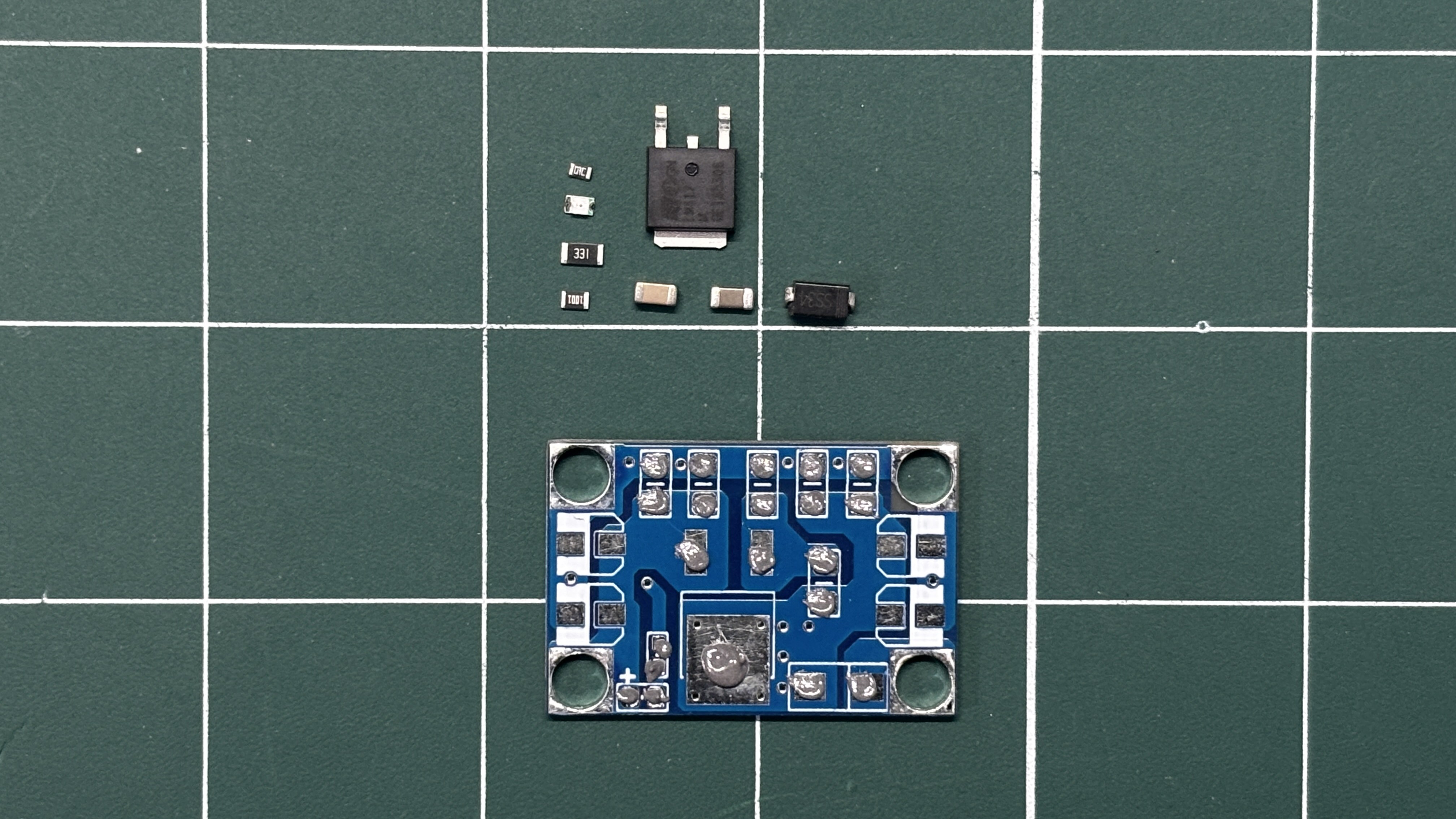
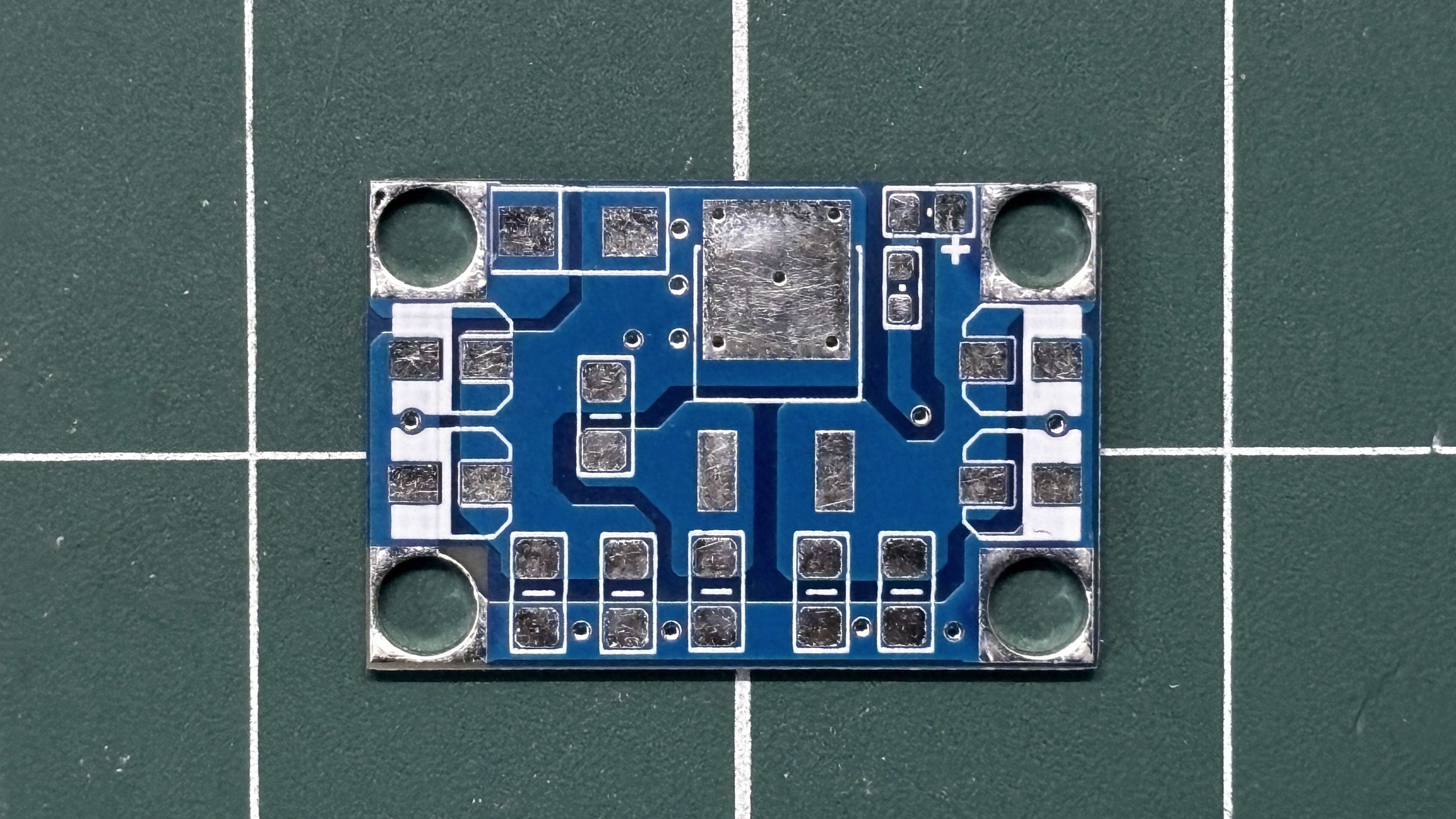
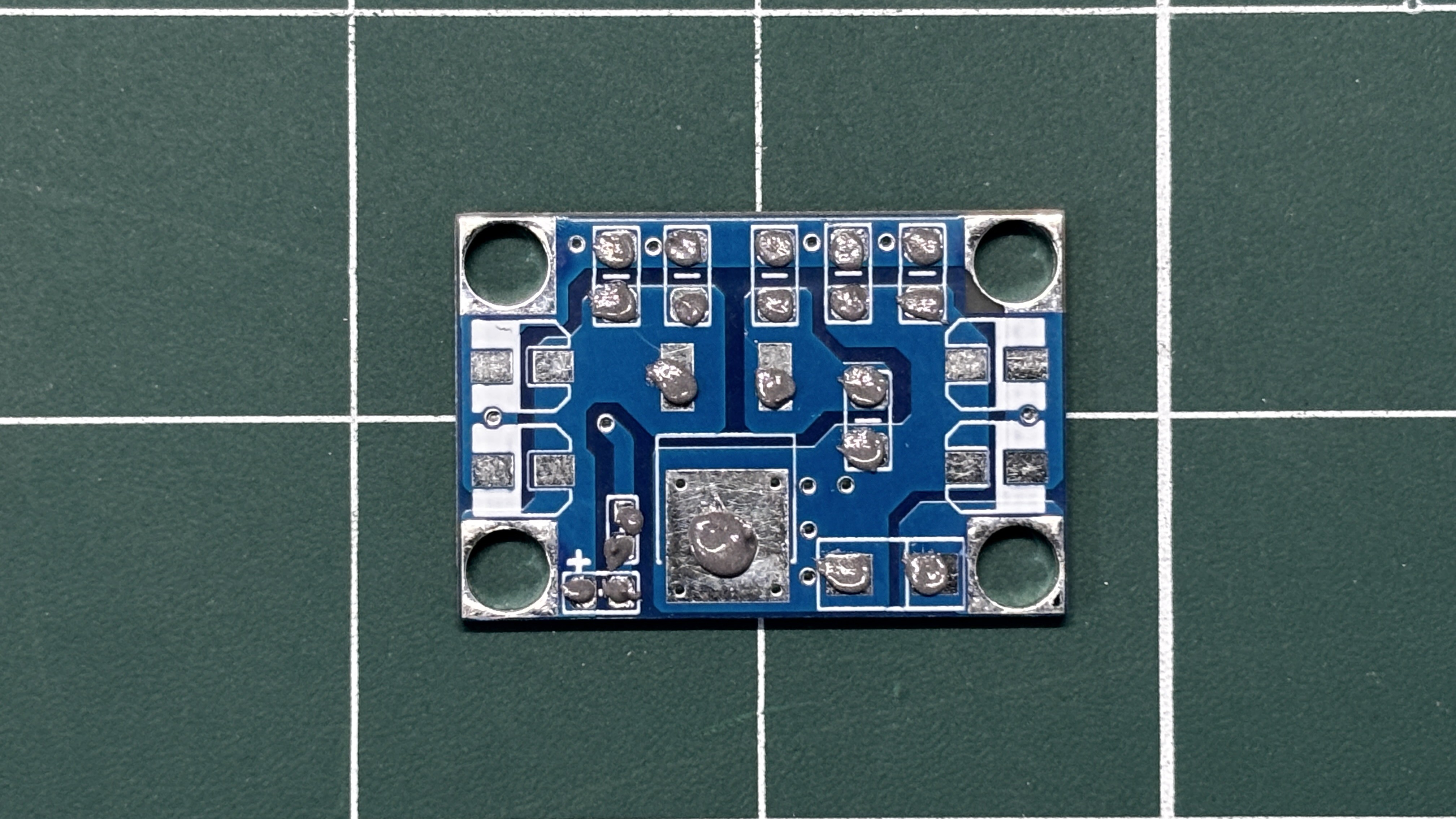
1PCB ASSEMBLY
![]()
![]()
![]()
![]()
![]()
- We begin the PCB assembly process by first adding solder paste to each component’s pads one by one using a solder paste dispensing needle. Here, we are using 63/37 SnPb solder paste.
- We then pick and place each SMD component in its correct location.
- The PCB is then placed on a reflow hotplate, which heats the PCB from below up to the solder paste melting temperature. As soon as the PCB reaches that temperature, the solder paste melts, and all components are secured in their positions, completing the PCB assembly process.
-
2SMPS TEST
![]()
![]()
![]()
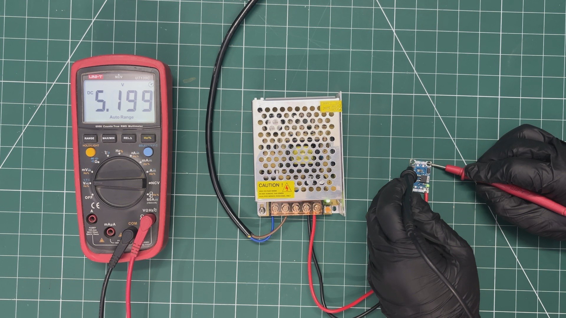
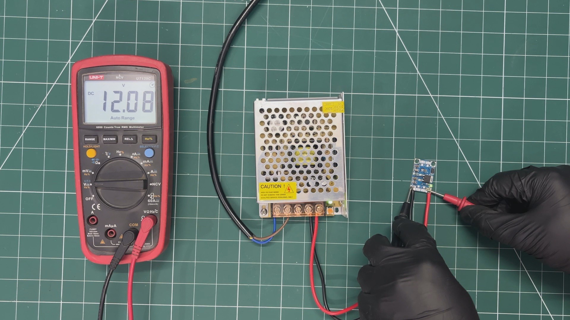
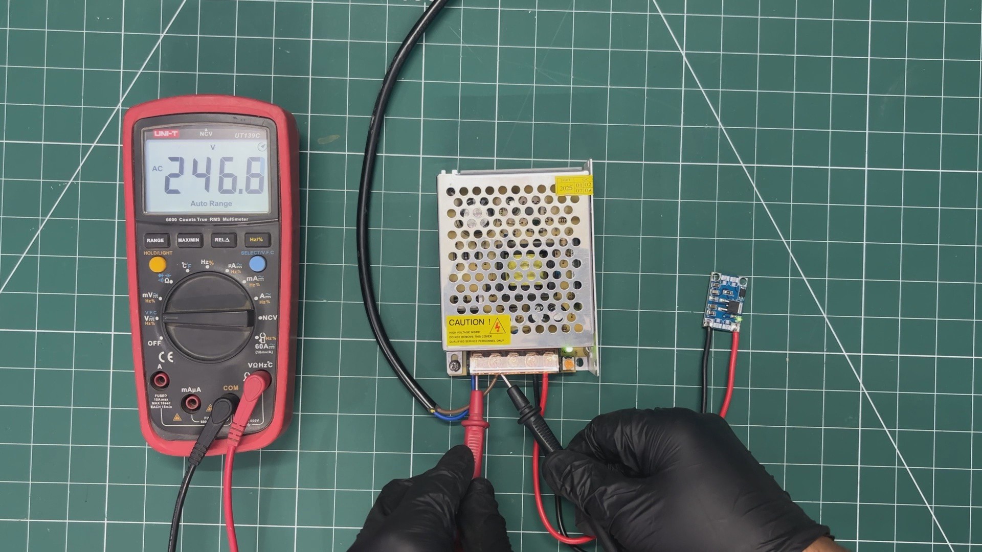
For the initial test of our buck converter, we used a 240V AC to 12V, 5A SMPS as the power source. We connected the VIN and GND of our buck converter to the 12V output of the SMPS.
Please note that we are working with AC here, so it is recommended to follow proper safety precautions and wear safety gear, such as gloves, while handling AC power.
Using a multimeter, we first measured the voltage across the AC input terminals to ensure that an AC voltage was present at the input of the SMPS.
Next, we measured the voltage across the input of the buck converter, which was around 12V.
Finally, we measured the voltage across the output of the buck converter, which was around 5V. This confirms that our setup is functioning correctly.
-
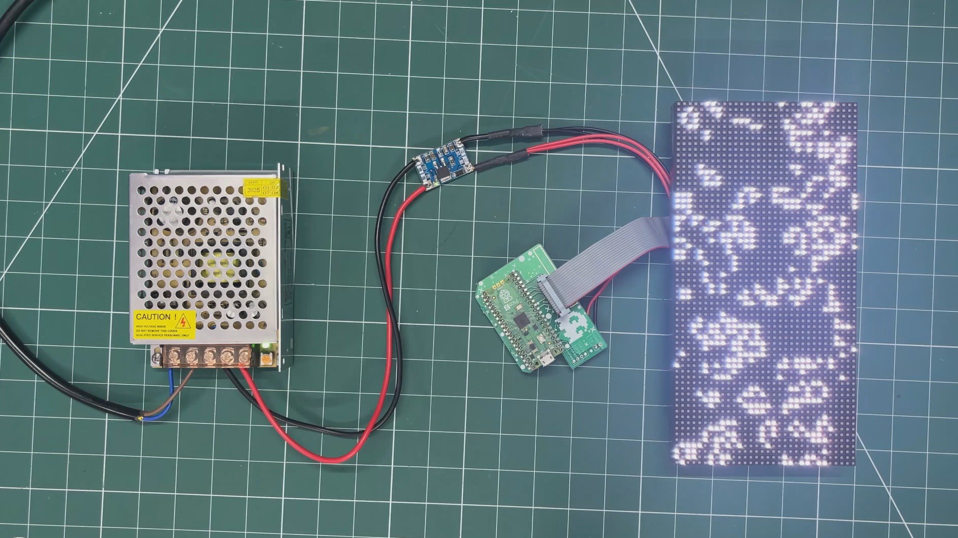
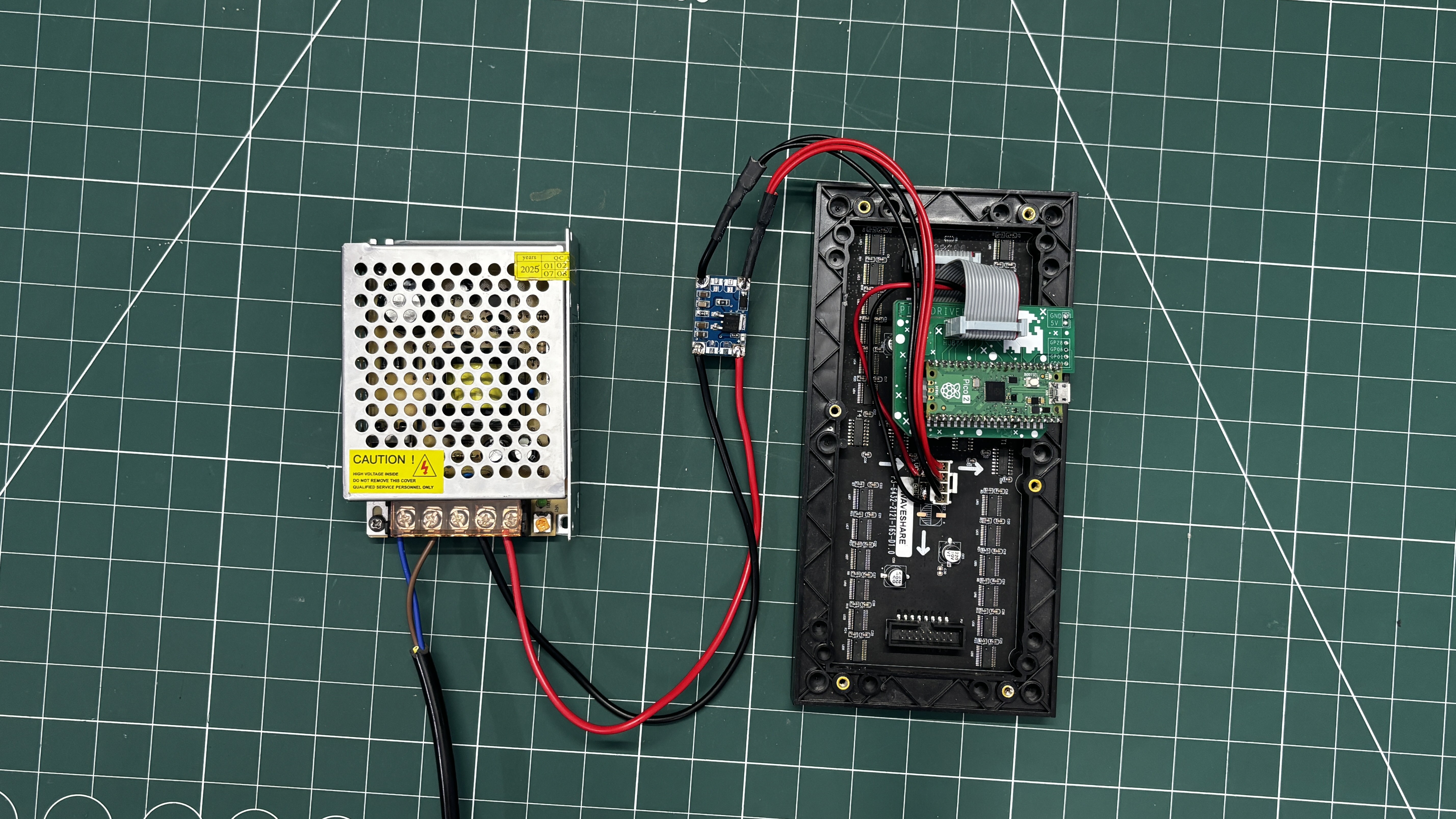
3Raspberry Pi PICO & RGB P3 Matrix DEMO
![]()
The next test for our buck module was a practical application.
We are working with an RGB 64×32 P3 matrix board, which requires a stable 5V, 3A supply, and this setup is driven by a Raspberry Pi Pico and is running our ported version of Conway’s Game of Life, which was perfect for the demo run.
You can check out the article below for a complete breakdown of how to use this matrix panel.
https://www.hackster.io/Arnov_Sharma_makes/64x32-matrix-panel-setup-with-pico-2-25a3c3
CODE
#include <Adafruit_Protomatter.h>
// Pin definitions
#define R1 2
#define G1 3
#define B1 4
#define R2 5
#define G2 8
#define B2 9
#define A 10
#define B 16
#define C 18
#define D 20
#define CLK 11
#define LAT 12
#define OE 13
#define WIDTH 64
#define HEIGHT 32
uint8_t rgbPins[] = { R1, G1, B1, R2, G2, B2 };
uint8_t addrPins[] = { A, B, C, D };
Adafruit_Protomatter matrix(WIDTH, HEIGHT, 1, rgbPins, 4, addrPins, CLK, LAT, OE, false);
bool grid[WIDTH][HEIGHT];
bool newGrid[WIDTH][HEIGHT];
void setup() {
matrix.begin();
randomSeed(analogRead(0));
// Initialize grid with random values
for(int x = 0; x < WIDTH; x++) {
for(int y = 0; y < HEIGHT; y++) {
grid[x][y] = random(2);
}
}
}
void loop() {
matrix.fillScreen(0);
// Update grid based on Game of Life rules
for(int x = 0; x < WIDTH; x++) {
for(int y = 0; y < HEIGHT; y++) {
int aliveNeighbors = countAliveNeighbors(x, y);
if(grid[x][y]) {
// Any live cell with two or three live neighbors survives.
if(aliveNeighbors < 2 || aliveNeighbors > 3) {
newGrid[x][y] = false;
} else {
newGrid[x][y] = true;
}
} else {
// Any dead cell with three live neighbors becomes a live cell.
if(aliveNeighbors == 3) {
newGrid[x][y] = true;
} else {
newGrid[x][y] = false;
}
}
if(newGrid[x][y]) {
matrix.drawPixel(x, y, matrix.color565(255, 255, 255)); // White color
}
}
}
// Copy newGrid to grid
memcpy(grid, newGrid, sizeof(grid));
matrix.show();
delay(100); // Adjust the delay for speed control
// Check if the grid is stable or empty
if(isGridStableOrEmpty()) {
resetGrid();
}
}
int countAliveNeighbors(int x, int y) {
int aliveNeighbors = 0;
for(int dx = -1; dx <= 1; dx++) {
for(int dy = -1; dy <= 1; dy++) {
if(dx == 0 && dy == 0) continue;
int nx = (x + dx + WIDTH) % WIDTH;
int ny = (y + dy + HEIGHT) % HEIGHT;
if(grid[nx][ny]) {
aliveNeighbors++;
}
}
}
return aliveNeighbors;
}
bool isGridStableOrEmpty() {
for(int x = 0; x < WIDTH; x++) {
for(int y = 0; y < HEIGHT; y++) {
if(grid[x][y]) {
return false;
}
}
}
return true;
}
void resetGrid() {
for(int x = 0; x < WIDTH; x++) {
for(int y = 0; y < HEIGHT; y++) {
grid[x][y] = random(2);
}
}
}
After flashing the Pico with the above code, we connected the matrix’s VCC and GND to the VOUT and GND of the LM317 buck converter board. We then turned on the SMPS, and the setup started functioning successfully.
-
4CONCLUSION
![]()
The conclusion of this build is simple: our LM317 buck converter works quite well and can be used with the matrix setup we tested. Not just the matrix, the output voltage of the board can be easily adjusted by changing the values of R1 and R2, allowing it to be used with a variety of applications. For now, we will be using this board in a display-related project and also in a Raspberry Pi 4–based project, which we will be posting shortly.
With that, the project has been finalized, and all the related documents are attached in this article. Special thanks to NextPCB for providing PCB services for this project—you can check them out for reliable, high-quality PCB services at a great price.
Thanks again for reading this far, and peace out!
DIY LM317 Based Buck Converter
Made a super small Buck converter module based around LM317 that can provide a stable 5V for powering XYZ electronics.
Discussions
Become a Hackaday.io Member
Create an account to leave a comment. Already have an account? Log In.