 Allan Binder
Before the HV boost modules arrive (40 days in transit), I wanted to validate as much of the detection circuit as possible using just the ESP32 itself. The idea is simple: use one GPIO as a signal generator to inject fake pulses into the front end, and use another GPIO to listen for interrupts at the output. If the right number of pulses come out the other end with the right timing, the chain works.
Digital chain first
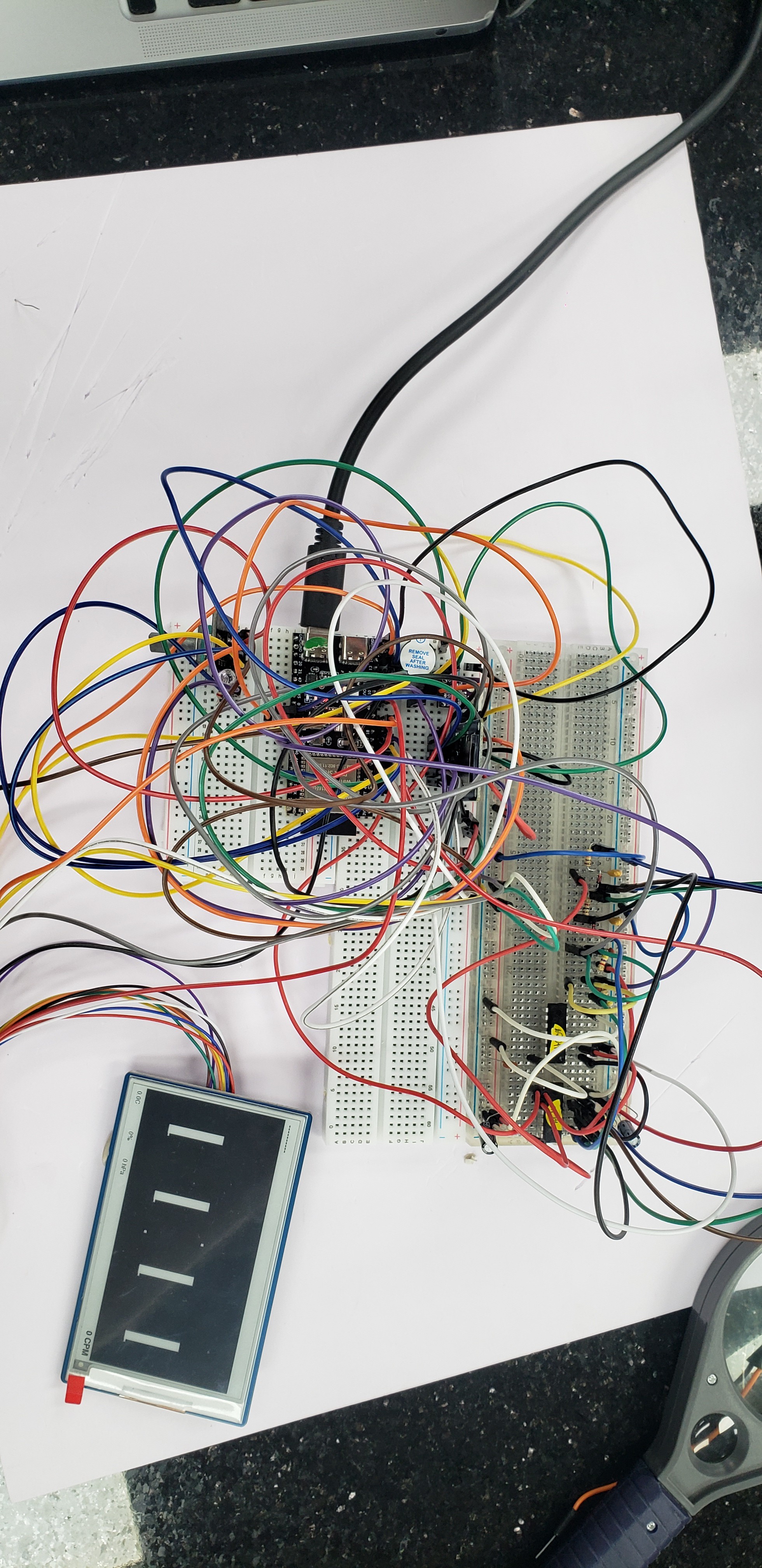
I started with just the digital side, the 74HC14 pulse shaping, BAT54/RC stretcher, second 74HC14 re-squaring stage, and the 74HC08 AND gate. I wrote a quick sketch that toggles a GPIO to produce short pulses at a known rate, fed those into the 74HC14 input, and counted rising-edge interrupts on the AND gate output with a separate pin.
For single-channel testing I injected pulses into one channel at a time and confirmed the ESP32 counted every one. For coincidence testing I fed the same pulse into both channels simultaneously. The AND gate output fired on every injected pulse, which is exactly what you'd expect when both inputs see the same signal at the same time. I also confirmed that pulsing only one channel produced zero coincidence counts on the output. That's the whole point of the AND gate and it's reassuring to see it actually reject single-channel events.
Not the most sophisticated test, a logic analyzer would let me see the actual pulse shapes at each stage and verify the stretcher timing. But for a go/no-go check of "is this circuit wired correctly and are the ICs behaving," it's enough. The logic analyzer is sitting on my desk for when I need it later.
Then the analog front-end
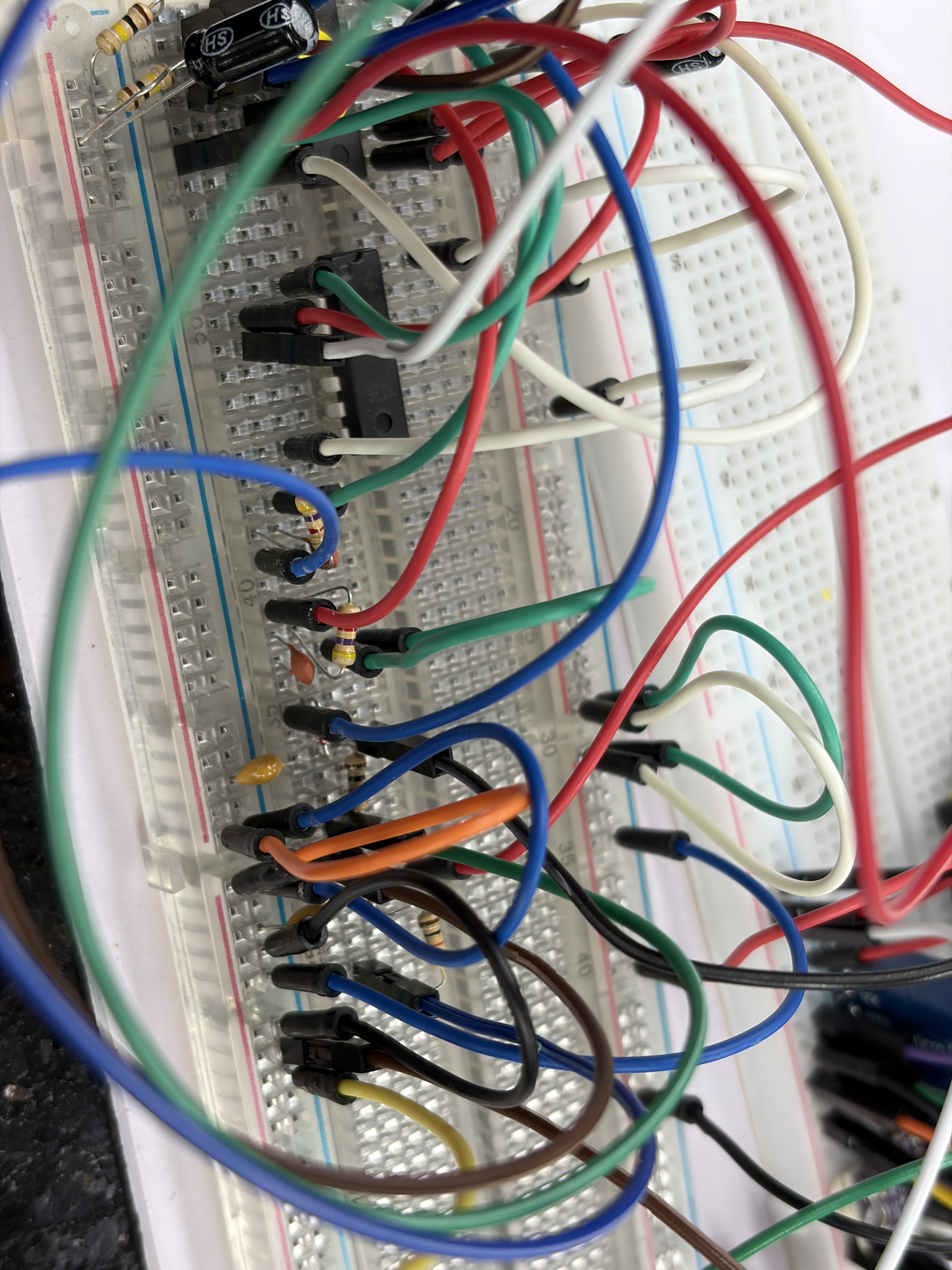
With the digital chain proven, I wired up the analog input network: the 1nF coupling caps, 4.7kΩ series protection resistors, and 100kΩ bias pull-downs that sit between the GM tube cathodes and the 74HC14 inputs. No tubes, no HV, just the passive components that will eventually condition the real cathode pulse.
Same test: synthetic pulses from the ESP32 into the analog input side, interrupt counting on the coincidence output. The pulses now travel through the full path, coupling cap, bias network, first Schmitt trigger stage, stretcher, re-squaring, AND gate. Everything that isn't the tube and HV module.
It worked. Same pulse counts in, same counts out. The coupling caps and bias resistors aren't filtering out or attenuating the synthetic pulses, which makes sense because the ESP32 GPIO puts out a clean 3.3V edge that's well above the 74HC14's ~1.9V threshold. The real question is whether actual GM tube cathode pulses will be strong enough, and that's something I genuinely won't know until the HV modules show up and I can power a tube.
That's the next milestone: HV module bring-up. The boost converters are still in transit, so in the meantime I've been working on the e-ink display which turned into its own adventure. More on that next time.
Discussions
Become a Hackaday.io Member
Create an account to leave a comment. Already have an account? Log In.