I have been thinking about building a Muon based RNG device ever since watching an Alpha Phoenix video on Youtube. It seemed like such a cool way to have a direct connection to both sub-atomic and astronomical scales. I mulled the idea around for ~2 years and finally decided to pull the trigger.
I haven't designed a circuit from scratch since high school, but I have done a number of repairs on analog equipment working as a sound engineer over the years, so the first thing I wanted to do was draw out the schematics to make sure I understand everything and can start preparing myself mentally for dealing with analog components without an instruction manual. Specifically because the 2x (I've updated the design to use 4x, not pictured in these drawings) high voltage boosters are not something you can really troubleshoot on the breadboard without burning the rest of the hardware.
Next week: the digital chain on breadboard, validated with a synthetic pulse injector before any HV comes near it.
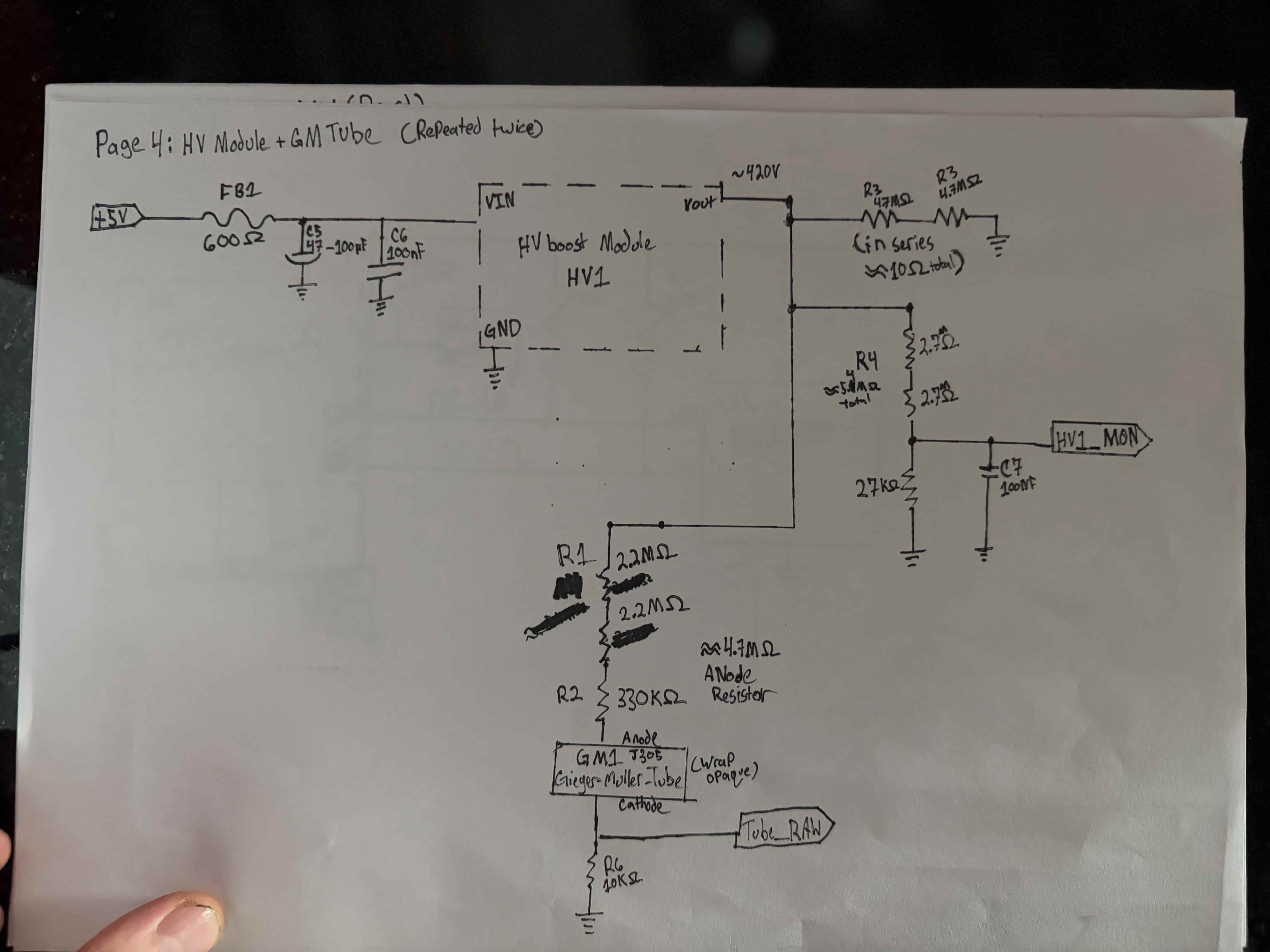
Page 1 of the sketch set. USB-C 5V in, AMS1117 LDO dropping to 3.3V for peripherals, ferrite beads isolating the two HV boost modules so their switching noise stays out of the logic rail.Page 2, repeated for both tubes. HV module trimmed to ~420V, series-stacked resistors on the anode and bleeder (no single resistor sees more than its rated working voltage), and a divider down to ~2.2V for the ESP32 ADC to monitor. The tube cathode is where the signal is picked off, not the anode.
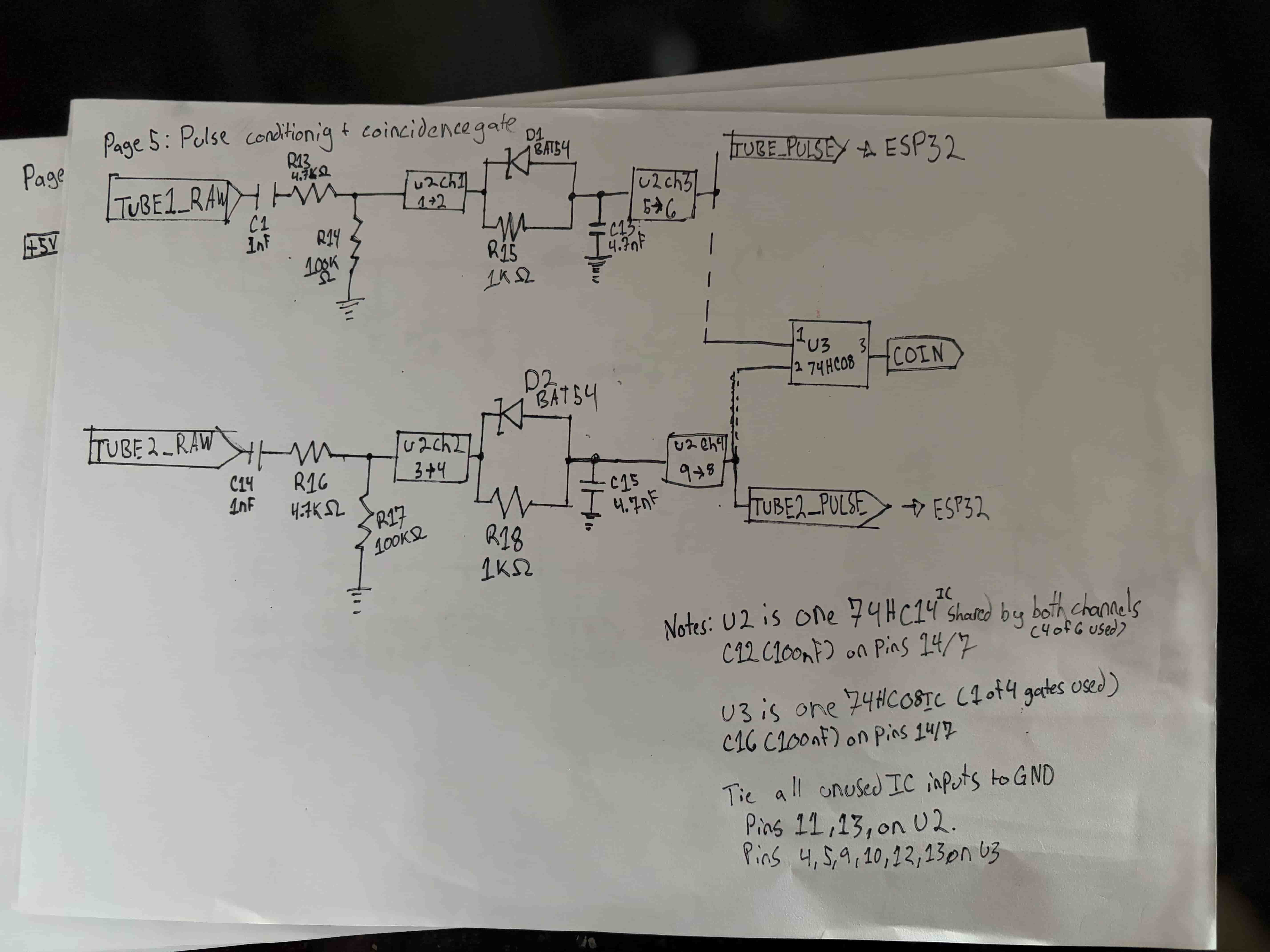
Page 3, the heart of the detection circuit. Each tube's cathode pulse gets AC-coupled, shaped through a 74HC14 Schmitt trigger, stretched with a BAT54 diode and RC network to ~3-5µs, then re-squared through another 74HC14 channel. Both stretched pulses feed a 74HC08 AND gate. Its output fires only when both tubes trigger within the coincidence window which is the muon signal.
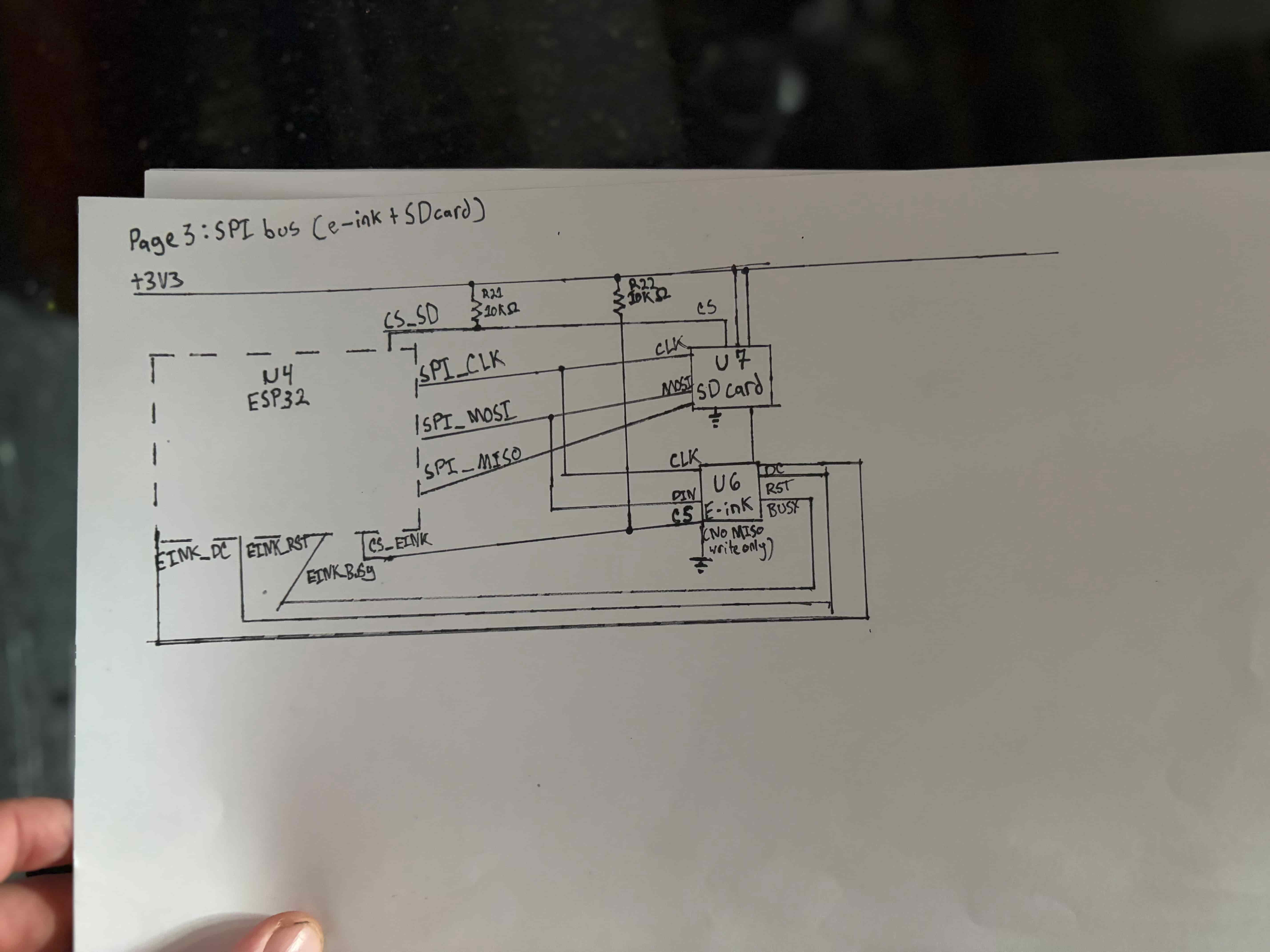
Page 4. The e-ink display and SD card share MOSI and CLK but get their own chip-select pins (with pull-ups so both stay deselected during boot). Only the SD card uses MISO — the e-ink is write-only.
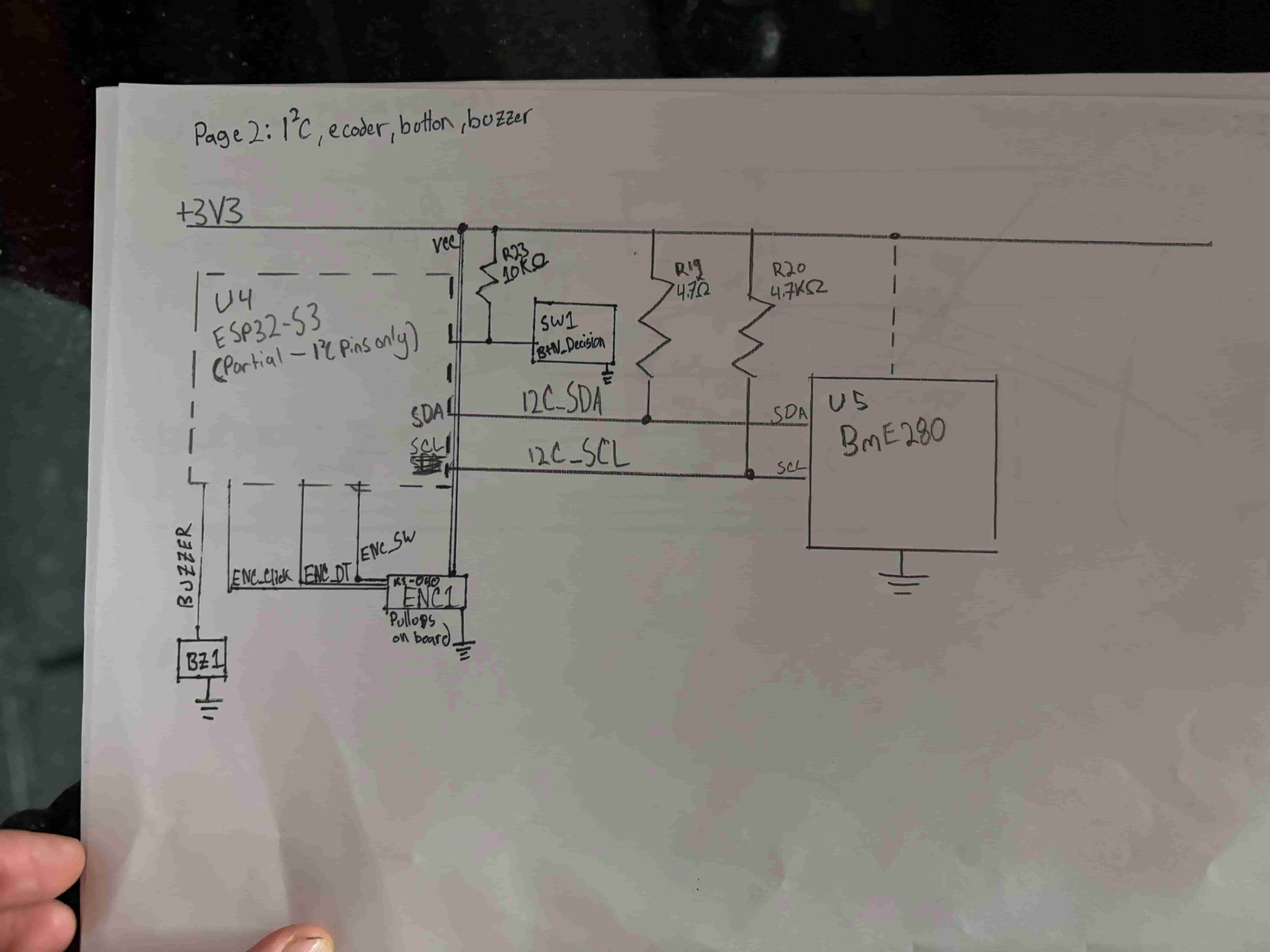
Page 5. BME280 environmental sensor on I²C, KY-040 rotary encoder for navigation, dedicated decision button (the hero interaction so it's kept physically separate from the encoder), and a passive piezo for audio feedback.
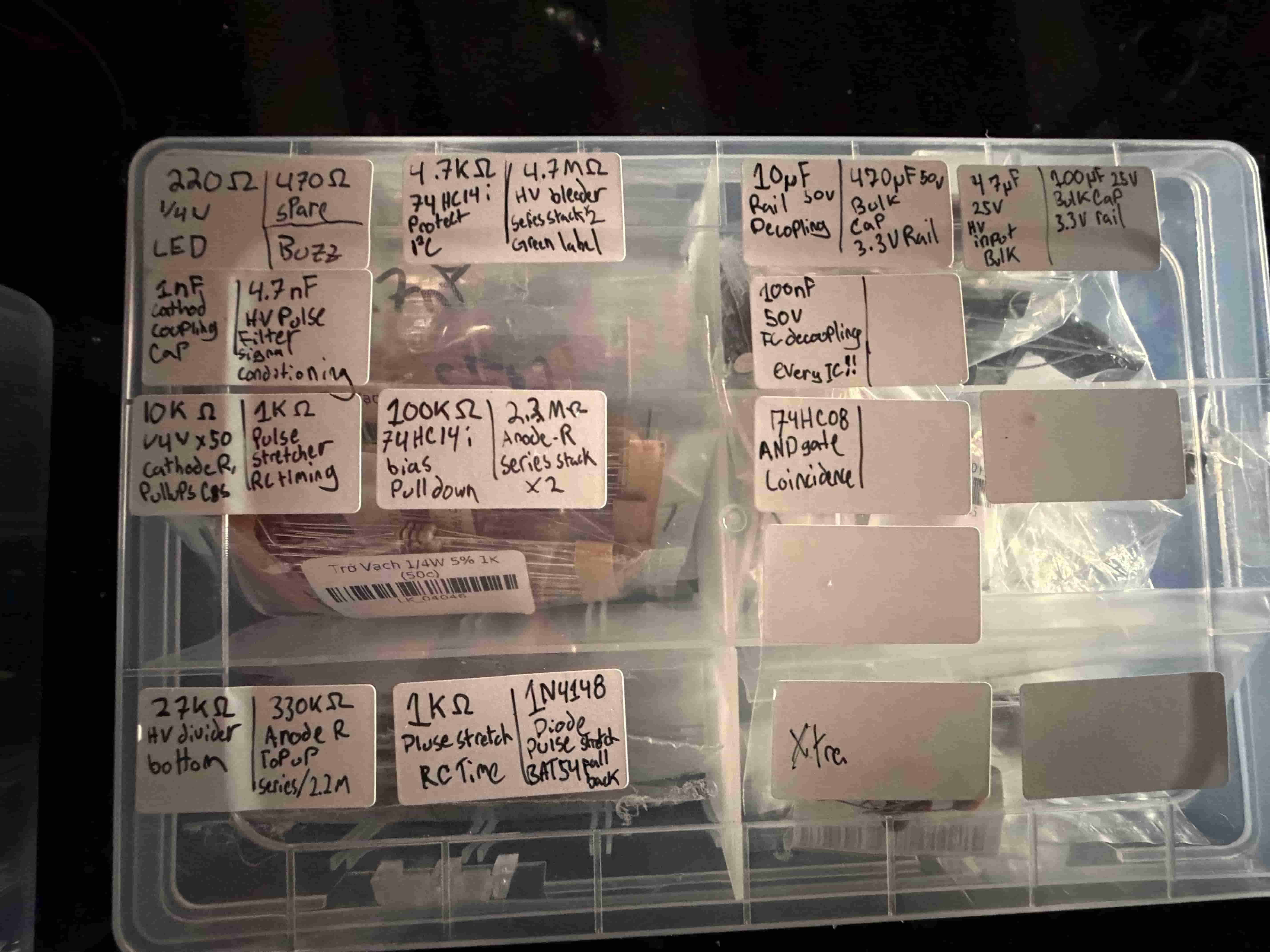
Every component bag hand-labeled with value, purpose, and where it goes in the circuit. "100nF -> IC decoupling -> every IC!!" is for future me at 2am who forgot to drop a cap next to a chip.
*Missing page 6, the ESP32-S3 pinout map. Forgot to photograph it.
 Allan Binder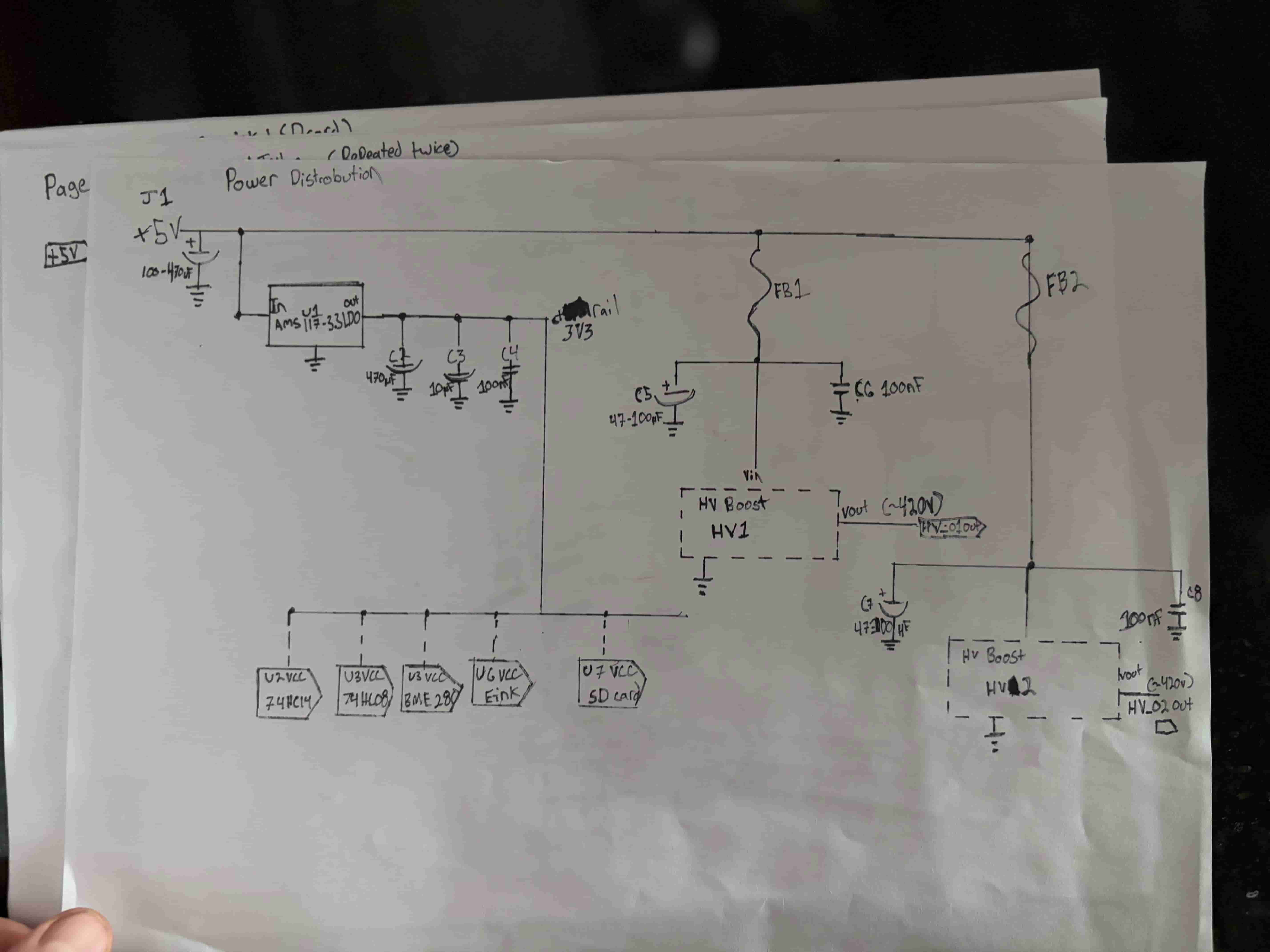
Discussions
Become a Hackaday.io Member
Create an account to leave a comment. Already have an account? Log In.