 electronicsworkshops
Introduction
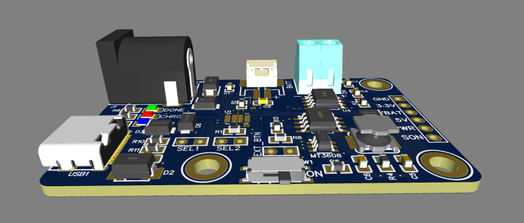
The LiPo Power Board functions as a power controller for devices powered by batteries, mainly aimed at prototyping use due to its breakout-style design. It operates with a single 3.7V LiPo cell and delivers two voltage outputs: a stable 3.3V and another adjustable output that can supply higher voltage and current levels. A built-in switch enables users to turn off power to both outputs when needed. The board supports battery charging through USB-C and DC jack connectors.
One of its key advantages is the flexible boost converter section, where the output voltage can be easily modified by adjusting the ratio of two resistors. This design also allows duplication of the boost circuit to create additional voltage outputs if required.
This board is particularly useful in applications where a microcontroller operates at 3.3V while other components, such as sensors or devices like WS2812B LEDs, require a higher and more stable voltage supply.
For Full Project: https://electronicsworkshops.com/power-management-board-for-battery-powered-projects/
Features
Low leakage current design for improved battery efficiency
3.81mm pin spacing for easy integration and compatibility
Includes 3D model support for accurate design and enclosure planning
Minimum guaranteed output current at 5V: over 400mA (tested at 3.3V input)
1. Input Power Section (USB & DC Connector)
- The board accepts input power from:
- USB connector (USB1)
- DC jack (DC-005-20A)
- Input protection includes:
- TVS diode (SMAJ5.0A) (Note 4) to suppress voltage spikes
- Schottky diodes to prevent reverse current flow
- USB resistors (R10, R11 = 5.1kΩ) configure proper USB-C behavior.
2. On-Off Control Circuit
- A physical switch (SW1) controls the ON_SIG signal.
- A pull-down resistor (R6) (Note 5) ensures the system does not power up unintentionally.
- This signal enables/disables regulators and boost circuits.
3. Battery Charging Circuit
- Main IC: MCP73831T LiPo charger
- Key features:
- Supports charging from USB (max 500mA) or DC input (up to 1A)
- Charge current is set by R2 (1kΩ) (Note 2)
→ Increasing/decreasing this resistor changes charging current. - Status LEDs (D7, D8, D9) indicate charging states.
- Protection:
- Input current limiting resistors and diodes
- Capacitors (C1, C2) for filtering
- Temperature sensing:
- Placeholder resistor for thermistor (Note 3)
→ Can be replaced with a real battery temperature sensor.
- Placeholder resistor for thermistor (Note 3)
- Special mode:
- Can operate as LDO (no battery) (Note 5)
→ Requires Vtherm > Vdd – 100mV (SEL configuration).
- Can operate as LDO (no battery) (Note 5)
4. Battery Connector
- JST connector provides connection to the 3.7V LiPo battery
- Includes decoupling capacitor (C7 = 4.7µF) for stability.
5. 3.3V Regulator Section
- IC: MCP1725 LDO regulator
- Converts VBAT → stable 3.3V output (VCC)
- Features:
- Low dropout voltage
- Enable control via ON_SIG
- Capacitors:
- Input/output capacitors ensure stability (Note 9: Cin ≥ Cout and placed close to VIN)
6. 5V Boost Converter Section
- IC: MT3606 boost converter
- Steps up battery voltage (3.0–4.2V) → 5V output
- Output voltage set by resistor divider: Vo = 0.6 × (1 + R4/R5) (Note 7)
- Inductor (L1 = 10µH) and diode (Schottky) are essential for boost operation.
- Important limitation:
- The MT3606 cannot fully disconnect output (Note 6)
→ Even when EN is LOW, leakage path from VBAT to 5V exists.
- The MT3606 cannot fully disconnect output (Note 6)
- Schottky diode drop:
- Around 0.35V at 2A (Note 8), affecting efficiency.
7. Load Switch / Power Gating
- MOSFET array (Q1) controls power delivery to outputs.
- Ensures safe switching of voltage rails.
- Controlled via ON_SIG signal.
8. Output Header
Provides multiple accessible signals:
- VCC (3.3V)
- VBAT (raw battery voltage)
- +5V (boost output)
- PWR_GOOD
- ON_SIG control
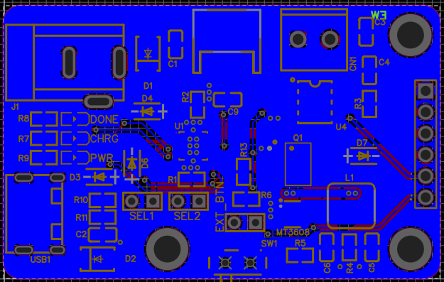
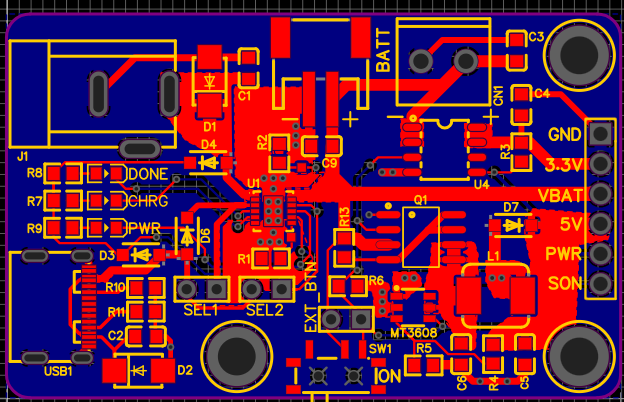
Pcb Files
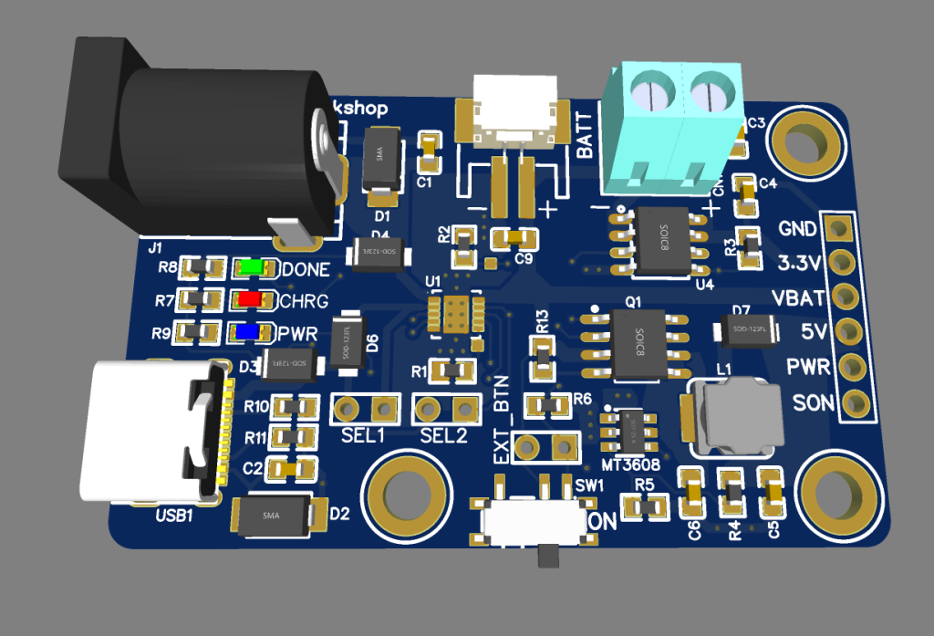
3D files

Order Directly from PCB WAY
I have already uploaded all these required manufacturing files in PCBWAY website. You can easily go to the below link and place you order, and get...
Read more »