 Charlie Theobald
My last few exams went considerably better than the three exams I had before the last update. I might actually pass the year.
As of Tuesday all my exams are finished, which means I have much more time on my hands, and have been able to start building my home electronics lab.
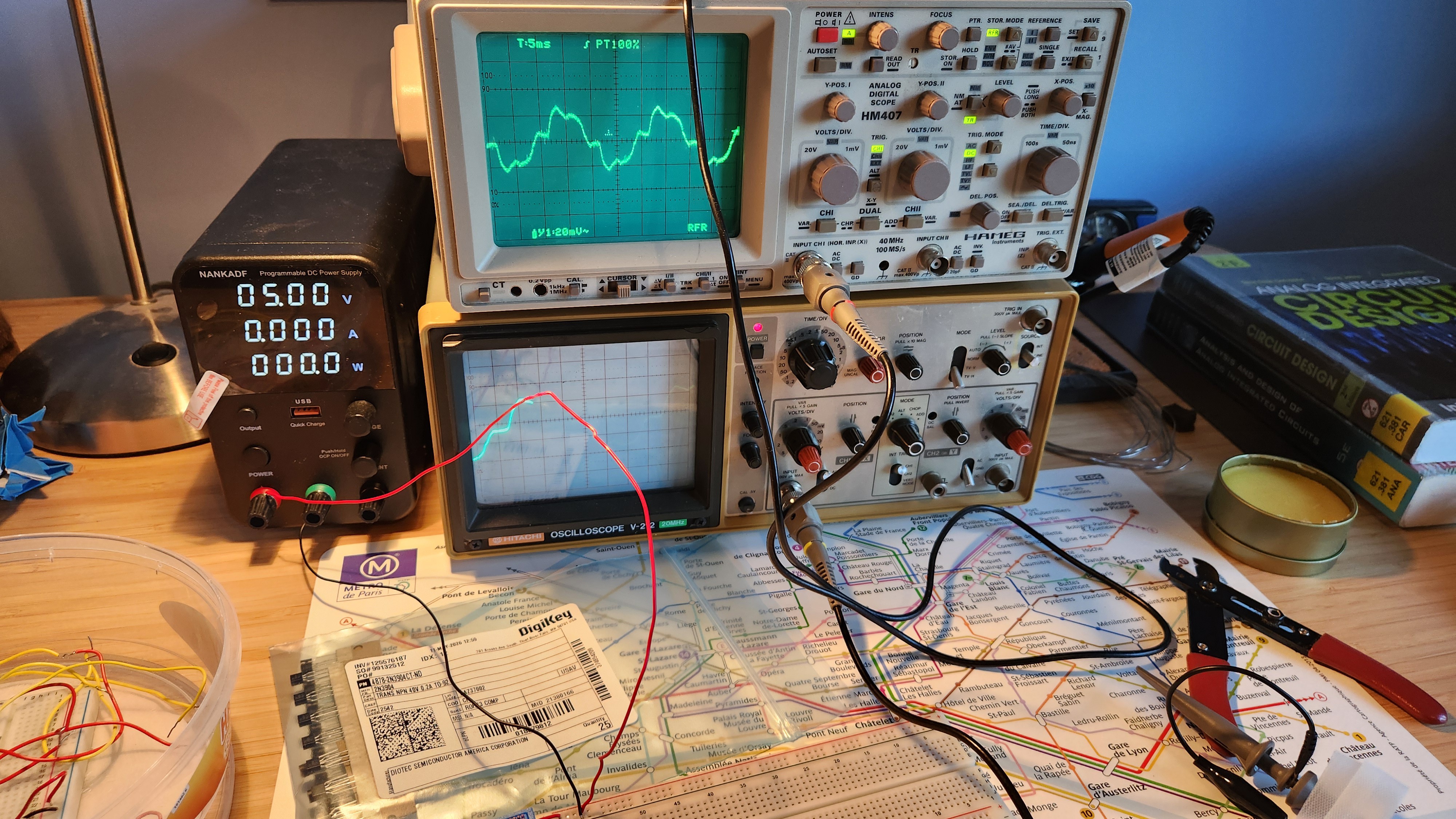
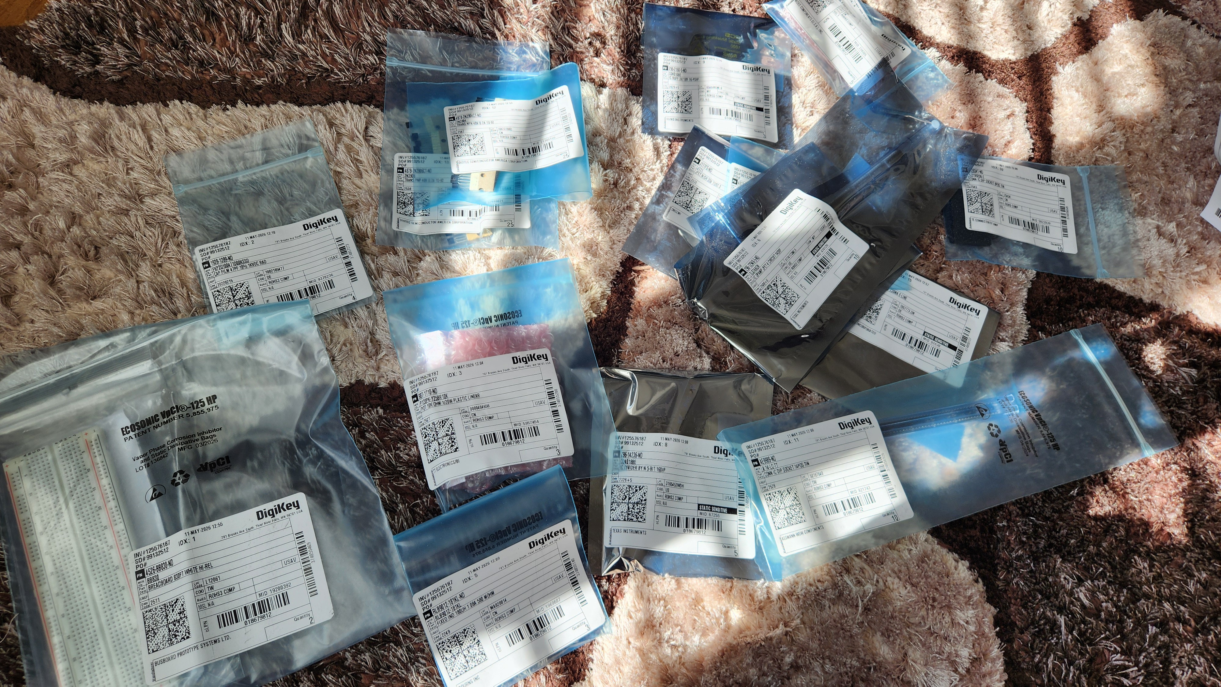
It couldn't be any better timing; a large order from DigiKey arrived on Wednesday and another from Retroamplis on Thursday. Before we start talking about oscillator architectures, I'll list everything that came through the post this week for recordkeeping sake.
In the post
| BB830 solderless breadboard x2 | £13.26 |
| 47pF film capacitor x4 | £1.88 |
| 10K rotary pot x3 | £3.15 |
| 100K trim pot x4 | £3.45 |
| 180uH inductor x3 | £1.38 |
| TL074 quad JFET op-amp 14DIP x10 | £5.99 |
| J111 n-channel JFET x5 | £1.70 |
| CD4018BE 5-bit divider by N 16DIP x5 | £4.70 |
| CD4010BE buffer 16DIP x3 | £1.92 |
| 8DIP IC sockets x10 | £1.50 |
| 14DIP IC sockets x10 | £1.42 |
| 2N3904 NPN transistor x25 | £1.63 |
| 2N3906 complementary PNP transistor x25 | £1.63 |
| 2N7000 n-channel MOSFET x10 | £1.33 |
| BS250P p-channel MOSFET x5 | £5.65 |
| M082AB1 13-note Top Octave Generator 16DIP x4 | £35.81 |
This is a total expenditure of £86.40, bringing the total spend so far up to £129.25. This is a very significant order, and will probably be one of the largest of the whole project.
Choosing a VCO architecture
There are many different VCO architectures used in synths from the valve era right through to the present day. For musical use, they must all be of excellent accuracy to reproduce pitches well, no matter the temperature, environmental noise or any other initial conditions.
Phase-shift oscillator
An oscillator, in its simplest form, is an amplifier with gain greater than 1, and a feedback network providing an overall phase shift of 360 degrees (such that the feedback signal superposes with itself). This is a necessary, but not sufficient, condition for oscillation known as the Barkhausen stability criterion.
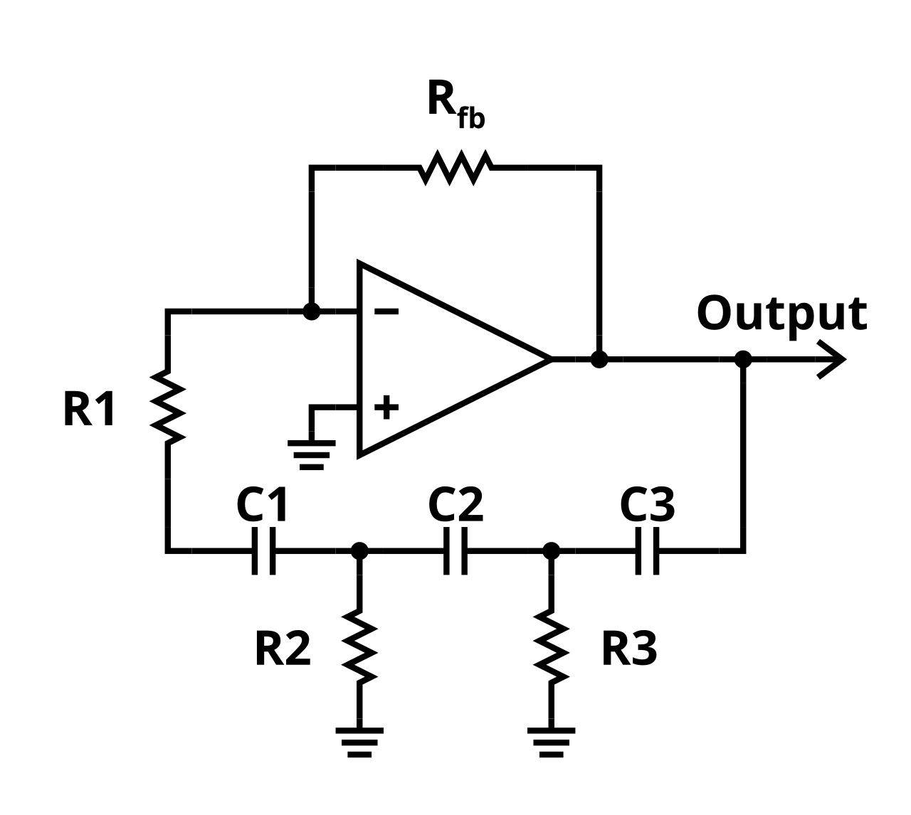
Above is a schematic of a simple phase-shift oscillator. In the example above, the three RC stages provide a combined 180 degrees of phase shift, and the op-amp adds another 180 degrees of phase shift at the output as the signal is fed into the inverting input.
The circuit produces a sinusoidal output voltage, with frequency of oscillation is given by

There are a couple of problems with this circuit that make it unsuitable for use in our synthesizer.
- The op-amp output will either grow or shrink exponentially unless the feedback resistor R_fb is set to an exact value. As our op-amp supply rails are limited, significant distortion may occur if the signal grows and clips at the rails, or worse the output voltage collapses as the closed-loop gain becomes less than 1.
- The output is a pure sine wave. Analog synthesizers use the principle of subtractive synthesis. This means that they start with a harmonically rich sound like a sawtooth, square or triangle wave, and shape the sound using VCFs and tone filters. A pure sine wave has no harmonics, so we cannot tailor the sound to our liking.
- Voltage control of the oscillator is challenging, as we need to simultaneously modify the feedback network whilst ensuring the open-loop gain remains 1. This means it's not suitable for varying frequency.
(N.B a technique called additive synthesis also exists, where sounds are synthesized by summing sinusoidal waveforms together. As many fundamental waveforms require infinite sums of sinusoidal waveforms, additive synthesis uses a lot of hardware very quickly.)
A circuit like this may be useful for low-frequency modulation at a fixed frequency such as tremolo / vibrato, but we need to continue our search to find something better.
Relaxation oscillator
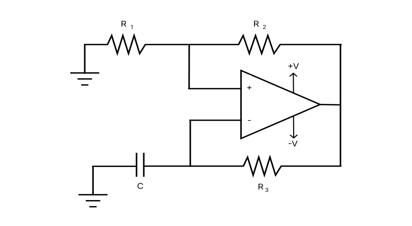 The relaxation oscillator is one of the most commonly used oscillators for producing square and triangle waves. It takes the form of an op-amp configured as a Schmitt trigger, which is a type of comparator with two voltage thresholds determined by the output voltage, R1 and R2, plus an RC discharge network (R3 and C) which creates a periodic oscillation. The relaxation oscillator is the working principle behind the legendary NE555 timer chip.
The output of this circuit will be a square wave as the Schmitt trigger flips between its two output states, with the voltage across the capacitor being a passable approximation of a triangle wave. Voltage control of the frequency is now much more easily implemented, as we can vary the frequency simply by changing R3 (or indeed C, though variable resistance is much more common).
This circuit is simple and solves some of the issues with the phase-shift oscillator, but is still not fantastic.
- The oscillator is quite unstable in frequency as it lacks any real negative feedback to preserve the resonant frequency.
- In an op-amp implementation, the maximum frequency of the oscillator is limited by its slew rate and bandwidth
- The oscillation is created by an RC network, which creates significant "rounding" as the capacitor takes time to charge, especially for low frequencies.
The relaxation oscillator is commonly used in things like alarms or extremely cheap audio equipment, that sort of just needs to make a sound or oscillate; where frequency stability or bandwidth isn't really that important. They are rarely used in synthesizers or applications where stability is important.
If we're staying true to the 1970s/80s, fast and precise op-amps were not nearly as widespread as they are now. Discrete transistors were more frequently used as they have much faster switching speeds. After turning to schematics from synth service manuals of the period for some inspiration, there's one particular type of oscillator that caught my interest.
The clock-divider VCO (or DCO)
The clock-divider oscillator uses an extremely stable master oscillator that generates a clock signal, typically in the MHz range. This is fed into a specialised chip known as a top octave generator (TOG) that divides this clock signal by an integer to obtain the "top octave" of the keyboard. This signal is then fed through a divider-keyer, which is effectively a set of divide-by-2 flipflops, to generate all octaves on the piano keyboard.
This is exactly how many late 70s/early 80s polyphonic synths generated their waveforms.
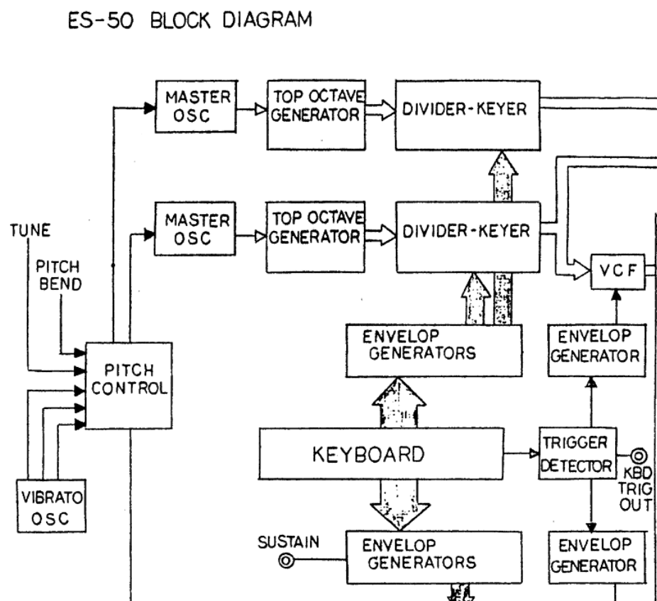
This architecture is significantly more complex, and blurs the boundary between analog and digital, but it is significantly more robust and frequency stable than free-running oscillators (like the phase-shift and relaxation oscillator). Some synth enthusiasts would argue that clock-divider VCOs are so precise they feel almost clinical, as they lack the "analog imperfections" of slight phase and frequency variations between notes. But my engineering brain tells me that it's always better to create something stable first then introduce controlled instability later, rather than settling for something suboptimal due to previous design choices.
One advantage of the clock-divider architecture is that because all notes on the keyboard are derived from the same clock, even if the master clock drifts slightly, the notes in a chord should always sound in tune relative to one another. Polyphony is also very easy to implement, as a single top-octave generator and divider-keyer can, and does, supply the frequency to every note on the keyboard. The only limitation to polyphony is the frequency of MIDI note events.
The most challenging part of the VCO design will be the master clock generator design. How can we design an accurate clock generator that meets our frequency stability requirement of 0.1%? Let's turn to two example designs for inspiration, one which I believe might be better than the other.
Evaluating clock generator designs
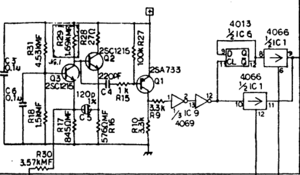
This is the master clock generator / oscillator from the Korg Lambda ES-50, released in 1979. The Lambda was considered a budget synth at the time of its release, so the electronics might be skimping a bit compared to Korg's cream of the crop (don't get me wrong, it's not a bad synth by any stretch of the imagination!)
While it looks a little complicated, analysis based on the Barkhausen criterion mentioned earlier simplifies the analysis a lot.
- This oscillator is centred on transistors Q3 and Q2, which are both configured as common-emitter amplifiers. As collector voltage of a CE amplifier is 180 degrees out of phase with the base voltage, the total phase shift in the loop is 360 degrees with a resonant frequency determined by C5 and R16. This satisfies the Barkhausen criterion.
- Transistor Q1 is a PNP transistor configured as an analog buffer, creating additional stability.
- C3 and C6 I believe are decoupling capacitors. Whilst they do slightly influence the resonant frequency of the oscillator, I don't think they're meant to.
The result is a near square wave at the collector of Q1. As the oscillator runs at quite a high frequency, despite C5 being tiny its rise time is likely to be significant. A quick check using the rise time approximation of a first order system gives t_r = 2.2RC = 150ns, which for the oscillation frequency of 2.3MHz makes up around 70% of the square wave on-time.
Is this acceptable? I'm not sure, and I suppose this is the purpose of the 4069 buffer after R9 to sharpen up the clock edges, but from my simulation the 4069 doesn't appear to have much effect, at least from a signal integrity perspective. Long rise times are generally bad for flip-flops as it increases the chance of them entering a metastable state during state changes.
On the other hand, as the oscillation is first-order, there will be no overshoot, undershoot or ringing of the clock, which is good. This could be a design compromise to prevent this from happening.
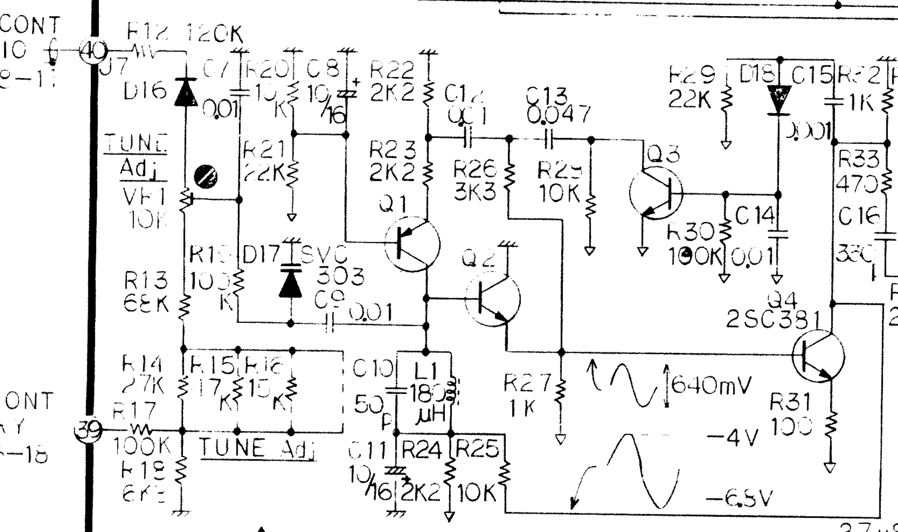
This is the master clock generator from the Roland Paraphonic RS-505, released in 1978 at a similar time to the Lambda. This was a high-end string machine, and has the design to back up the price tag. I must admit I don't completely understand this design yet, however it's clear this uses a second-order LC resonator made up of C10 and L1 and a much more complicated feedback network. As previously remarked in an earlier update, this synth uses 0V as the positive supply rail and -15V as the negative supply rail, supposedly also to improve stability by reduced electromagnetic effects.
For my master VCO, I'd like to take inspiration from both these designs, and form a Franken-VCO that interfaces well with the digital stages.
Next week, I'd like to construct these circuits and conduct a detailed real-world analysis of this circuit on a breadboard - if these circuits achieve good stability on the breadboard, they should still be reliable on a well-designed PCB, which I'd like to get sent off by the end of the month.
(Sorry, I lied about this being a purely analog synthesizer. Nevertheless, it's happening!)
Discussions
Become a Hackaday.io Member
Create an account to leave a comment. Already have an account? Log In.