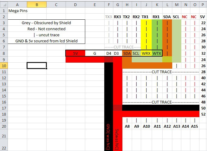
Just at work so had to use Excel to map my plans before I forgot ha ha!

Row 8 details the header for the Wemos D1 mini, and where it will sit on my perfrboard in relation to the Mega pins. It shall be mounted underneath, keeping the top free for Analog, Digital and i2c headers.
TX1 and RX1 go straight to the RX and TX pins of the D1 mini, with the SDA and SCL lines routed to meet pins D2 and D1 on the Wemos board.
5v and ground lines are added to the left of the board where no other pins are connected.
As you can see the 5v and the Ground pins of the Wemos will stick out underneath the board, but that is fine; in order to remove it you will need to remove the arduino shield first, and to install it you will have to plug in the expansion board first.
 Craig Hissett
Discussions
Become a Hackaday.io Member
Create an account to leave a comment. Already have an account? Log In.
Obviously if i get this designed properly I'll be able to route my connections alot better and not rely of the straight lines of the perfboard :-)
Are you sure? yes | no